Note: Descriptions are shown in the official language in which they were submitted.
2 1 ~ 9 P~ S 9~ ~ ~ L ~ ~ 5
IPE~ O 9 ~PK 1993
- Replacement Paqe
~E ' .~
Attorney Docket No. 11531-28PC
PHARMACEUTICAL DELIVERY SYSTEM
BAC~GROUND OF TXE INVENTION
Therapeutic in~ulin i8 of ~hree basic t~pes: fa~-
acti~g, intermediate-ac~ing a~d long-acting. In~uli~ u~erQ
o~en use a combi~ation of two type~ of insulin depending on
the u~er'~ hlood sugar leYel, the time of day, nouri~hme~t
intake and expeeted a~ti~ity. For example, i~uli~ injected at
~he b~gin~ing of an active day mBy ha~e ~ore o~ the fast~acting
insulin, while the in~ulin inje~tion given at the end of th~
day before going to bed would likely ha~e more i~termediate- or
long-ac~ing i~sulin.
One of the proble~s with co~ventio~al insuli~ ;
~yringes i8 tha~ they are de~igned to inject o~ly o~e type o~
insulirl, ~ot a eombinatio~. Although in~ulin ran b~ ob~ai~ed
a~ a mixture o~ the ~cwo type~, the mix~ures are ge~erally a ~e~
combination, ~uch as 70% i~termedtat~-acting aad 30~ ~as~-
ac~i~g. Thu~, ~he prior are limie~ the i~ulin u~er to a
prese~ mixture of ~he wo i~guli~ or ~he ~eed to make two
~eparate injec~io~.
SUMMARY OF THE INVENTION
The pre~e~ ~ention is ~irec~ed to a variable ratio :.
multipharmaceu~ical ~eli~ery ~y~t~m, typically i~ ~he ~orm of a
~yrl~ge, ~uitabla for he ~imulta~eou~ delivery o~ ~wo or more
m~xed flowabl~ phaxmaceuticals in ~elec ed amou~tq a~d
~O proportio~s. The delivery ~y~tem i~cludes f iXBt a~d ~e~o~d
~ariable volume re0~r~0irs, co~tai~i~g ~he ~ir~t ~d 0eco~d
pharmaceuticals, a~d a ~ariable ~ol~m~ acc ~ lator chamber.
Th~ re0ervoir~ and ac~u~ulator chamb~r ar~ pr~rably ~ormed
withi~ a c~mon bo~y. The r~ser~oir~ ar~ pre~erably con~e~ted
to ~h~ accum~lator ~h~ber ~hrough check valve~ ~o p~mi~ fluid
flow ~r~m the r~rvoir~ into ~h~ accumulator chamber but no~ -
th~ r~v~r~e. The~ d~li~ery sy~eem alio i~clud~ a deli~ery
head, typically a holIow ~eedle a~se~bly, ~lec~ively fluidly
. ~ ,
210t 3~i3
W092/15~5 PCT/USg2/~129~-
coupled to the accumulator chclmber. After the two
pharmaceuticals are dri~en from the reservoirs and into ~he
accumulator chamber, typically one pharmaceutical at a time,
the delivery head i.s fluldly couplecl to the accumulator chamber
and the mixture is forced from the accumulator chamber and
through the delivery head to permi~ administration of the
mixture, typically by injection.~
One of the key features of the invention is that the
first and second reservoirs and the accumulator chamber can be
made as integral parts of the delivery system. By making the
reservoirs and the accumulator chamber with a low-profile,
preferably elliptical, configuration, the delivery ~system can
be easily carried in one's pocket or purse while holding, for
example, sufficient insulin for several injections. Another
advanta~e of the in~ention is that, prior to a first injection,
and after each injection, the accumulator piston is positioned
fully within the accumulator chamber to permit the stem to be
fully housed within the acc~mulator chamher region~
With the delivery system configured as a flat,
rectangular product, reminiscent of a credit card, the delivery
system is easy to grasp and, when configured as a syringe,
quite suitable for ~elf-injection usage using one hand. When
used as a self-injection syringe for insulin users, the
invention reduces or eliminates the stigma of abnormality often
created by the use of conventional syringes.
Another aspec~ of the invention is the use of a novel
elastomeric val~e block which functions as a check valve. The
valve block pre~ents liquid from flowing back into either the
first or second reservoirs in a simpli~tic and economical
mannex.
The invention is described with the first and second
reservoirs and the accumulator chamber created using piston and
cylindex arrangements. However, other ~ariable volume
structures, such a~ ~lexible bags in which the volume can be
reduced by 3queezi~g or other manipulation, can be u~ed
ins~ead. Also, for enhanced ~terility, a flexible tubular
~kirt can be connected to the accumulator piston at one end and
to the proximal end of the accumulator chamber at the other.
W092/l5~5 2 l O 1 ~ ~ 9 PCr/U5~2/0l2~s
The invention, in one preferred embodiment, is
con~iyured as a syxinge using a hollow needle assembly as the
delivery head. However, the invention can be practiced using
needle-less injectors as well. The delivery head can also be
configured as a topical applicator using rollers or sprayer~ to
apply a liquid pharmaceutical direc~ly onto the patient's skin
or indirectly onto a bandage or patch, such bandage or patch :
being applied to the patient's skin. Spray-type delivery heads
can be configured for use as an inhaler as well.
Other features and advantages of the in~ention will -
appear from the followiny description in which the preferred
embodiments have been set forth in detail in conjunction with
the accompanying drawings.
BRIEF DESCRIPTION OF THE DRAWINGS
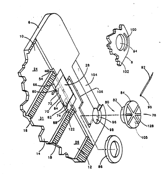
Fig. 1 is a partially exploded isometric view of a
multipharmaceutical syringe made according to the invention;
Fig. 2 is an enlarged, partially exploded isometric
view of a portion of the syringe of Fig. 1;
Figs. 2A, 2B and 2C are separate cross-sectional
views of the valve body o~ Fig. 2;
Fig. 3 is a plan view of a syringe of Fig. 1 shown
with the cover remo~ed, with portions of the base broken away
for clarity, and in its initial, as-shipped condition;
Fig. 4 shows the syringe of Fig. 3 with the first
liquid pharmaceutlcal in the first reservoir being forced into
the accumulator chamber, thus moving the accumulator piston
from the position of Fig. 3 to the position of Fig. 4;
Fig. 5 illustratas displacing the li~uid
pharmaceutical Erom the econd reservoir into the accumulator
chamber where it mixe~ with the first liquid pharmaceutical;
Fig. 6 shows the syringe of Fig. 5 with the needle
assembly moved from its stored posi~ion of Fig. 5 to its
extended po~ition of Fig. 6 and the expulsion of the now mixed
pharmaceutical li~iid from the accumulator cha~ber, through the
exlt path and through the hollow needle;
Fig. 7 is an enlarged view illustrati~g the
simultaneous flow of liquid from both the first and second
. . . -. ,, ~ , . . . ~ ~: .
21Ql~
W092/15~5 PCr/USg2/0l29.
reservoirs, through the valve block, and into the accumulator
cham~er, and then from the accumulator chamber, through the
exit path, and out the hollow needle;
Fig. 8 shows the syringe of Flg. 6 in its post-use,
s storage condition;
Fig. 9 is an enlarged cross-sectlonal view of an
alternative needle assembly of Fig. 1 including a removable
needle covered by a protective sheath;
Figs. lOA and lOB are front views of transparent
dosage labels;
Figs. llA and 11~ are simplified views showing the
accumulator piston and chamber of Figs. 3 and 4 used wlth a
sterility skirt;
Fig. 12 shows an alternatlve embodiment of the body
15 o~ the syringe of Fig. ~ having a xeplaceable, interchangeable . .
dispenser section;
Fig. 13 shows the base portion of the dispenser
section of Fig. 12 used with a spray nozzle as the delivery
head;
Fig. 14 illustrates an alternati`ve embodiment of the : .
dispenser section of Fig. 13 with the spray nozzle replaced by
a sponge pad-type topical pharmaceutical applicator; and
Fig. 15 illustrates an alternative embodiment of the
base portion of Fig. 13 in which the spray nozzle has been
replaced by a roller-type topical pharmaceutical applicator.
- DESCRIPTION OF THE PREFERRED EM~ODIMENTS
Referring the reader to Figs. 1-3, a
multiphar~aceutical syringe 2, especially useful fcr dispensing
insulin, includes a body 4 made up of a base 6 and a cover 8.
Ba~e 6 and cover 8 are pre~erably made of clPar,
phar~aceutically compatible plastic, such as polypropylene or
acrylic, and are joined, such as by ultrasonic weIding
techniques or using suitable adhesive. Base 6 has three
35 elongate, flattened elliptical cutouts 10, 12, 14 separated by
walls 16, 18. Fir~t and second pistons 20, 22 are sli~ably
moun~ed within cutouts 10, 12 and define first a~d second
vaxiable volume reser~oirs 24, 26. A valve body ~8 is mounted
W092~15~5 2 ~ 9 PCTIUS92/01295
:
in a cutout 27 formed ln base 6 at the distal end of elongate
cutout 14 for the reasons to be discussed below. An
accumulator pi.ston 30 is slidably molmted within cutout 14 to
define a variable ~olume accumulator chamber 31 bounded by base
6, valve body 28, body supports 33 formed at the distal end of
cutout 14 and accumulator piston 30. Pistons 20, 22 and 30 can
each be made from one piece of an elastomeric material, such as
silicone rubber. If desired, pistons 20, 22 and 30 can be
multi-component parts having a leading edge of a resillent
material, to provide a good seal, and a trailing edge OL a low
friction material, to provide guidance to keep the pis~ons from
skewing within their respective cutouts.
Syringe 2 also includes a stem 32 sized to fi'
substantially fully within cutout 14 when accumulator piston 30
is adjacent body supports 33 as shown in Fig. 3. Stem 32 has
raised finger grips 34 at its proximal end 36, proximal end 36
being enlarged to provide a good surface for the user to press
against. The proximal edge 38 of body 4 has a scalloped shape
to accommodate the arcuate shape of proximal end 36 to permi~ a
generally flush appearance a~ suggested in Fig. 3. Stem 32
also has a longitudinal guide slot 42 and a transverse guide
slot 44, guide slot 44 being positioned near the dis~al end 46
of stem 32. Slots 42, 44 are made to receive cylindrical gulde
pegs 48 which extend from the underside of that portion of base
25 6 overlying cutouts 10, 12, 14 along proximal edge 38. Guide
pegs 48 are best illustrated in Fig. 12 but are also ~hown in
dashed lines Fiy. 1; their positions are suggested in Fig. 3 by
broken circles. The guide pegs 4~ ~hat are aligned with
cutouts 10-14 travel alo~g guide slot 42 as stem 32 moves along
30 cutouts 10-14. Transverse guide slot 44 is used, as discussed
below, after stem 32 has been substantially remo~ed from body 4
and moved laterally to another cutout. The use of guide pegs
48 and guide slots 42, 44 both keeps stem 32 properly aligned
within the cutouts during use and also prevents stem 32 from
being completely removed fxom body 4 to both prevent its loss
and to maintain distal end 46 within accumulator chamber 31 for
enhanced qanitation.
..... . . . .
: . . ,, , : .
..
, ., .:, ~ ,. . . .
. .
.
: . , . . . , , , . -
.
21~ 9~
W092/15345 PCT/US92/0129'
The inner surfaces of elliptical cutouts 10, 12, 14
may be coated with a pharmaceutically compatible, low friction
material, such as PTFE sold by the DuPont Corporation of
Wilmington, Delaware under the trademark TEFLON. Other
coatings, which are ideally hard, low friction and inert, can
be used as well. For example, a thi.n coating may be deposited
onto the surfaces of cutouts 10, 12, 14 by appropriate vapor
deposition processes.
Referring now primarily to Figs. 2, 2A-2C and 4,
valve body 28 is made of an elastomerlc material, preferably a
silicon elastomer such as that made by Dow Chemical Company of
Midland, ~ichigan as Q7-4765. Valve body 28 iæ illustrated ln
~hese figures as it would exist when s~em 32 is pressing first
piston 20 thus forcing flrst liquid 52 within the first
15 re~ervoir 24 through a first flow path 54, formed in base 6,
through valve body 28 and into accumulator chc~mber 31. To do
so, valve body 28 includes first and second blind flow paths
56, 58. Blind flow pa~hs 56, 58 are preferably circular blind
holes formed in valve body 28. Valve body 28 also includes
first and second normally closed slits 60, 62 formed in valve
body 28 after valve body has been formed. Slits 60, 62, which
are in the pre~erred embodiment 0.100" wide, can be made by
forcing a thin blade, 0.006" thick and 0.100" wide, into the
face 64 of ~alve body 28 at positio~s chosen to intersect flow
paths 56, 58.
The thickness of valve body 28 at edges 66, 6a is
abuut 0.062" and is pre~erably ~lightly greater than the depth
of cutout 27; the width of ~ace 64 is preferably equal to or
slightly longer ~han the width of cutout 27. Thus, when cover
8 is mounted to base 6, ~alve body ~8 acts to seal accumulator
chamber 31 from first and second reservoirs 24, 26 except for
the flow paths fo~ed by blind flow paths 56, 58 and ælits 60,
62.
Valve b].ock 2a also includes a cu~out region 70
35 spaced apart from edges 66, 68. Cutout region 70 is about
0.010" deep and permits the opening of slits 60, 62 when first
and ~econd re~ervoirs 24, 26 are pressurized by the use of stem
32. Fig 2, 2B and 2C illustrate, in a æomewhat exaggerated
, ." ' .,., ~ ~ ' , '' ' ~ :
` W092/~5~5 ~~ ~ ~ 9 Pcr/usg~/ol2~
form, the opening of first slit 60 due to pressurization of
liquid 52 within ~irst variable vol~ne reservoir 24 by stem 32
as illustrated in Fig. 4. As seen in Figs. 2B and 2C, surface
72 created by cutout region 70 lying above first slit 60 is
permitted to bo~ upwardly thus permitting first sli~ 62 to open
thus opening a fluid path between first reservoir 24 and
accumulator chamber 32. However, second slit 62 acts as a
check valve, partially due to the pressurized fluid within
accumulator chamber 31 pressing on its overlyi.ng surface 74, to
prevent flow from accumulator chamber 31 to second reservolr 26
during this operation.
Syringe 2 further includes a rota~able needle
- asse~bly 78 mounted to body 4. Needle assembly 78 includes a
hub assembly having a hub 82 and end flanges 84, 86. Hub 82
has a bore ~8 formed therethrough ror receipt of one end 9o of
a hollow needle 92. Needle 92 is secured within base 88 by an
epoxy adhesive 93. Cover 8 and base 6 include holes 94, 96
sized for receipt of hub 82. The axial length of hub 82 is
about equal to the combined thickness of base 6 and cover 8.
With end flange R4 resting agai~st the outer surface ~02 of
cover a and end ~lange 86 resting against the outer surface 98
of base 6, flange 86 is secured to hub 82, such as with an
adhesi~e, to securely mount needle assembly 78 to body 4.
The pivotal movement of needle assembly 78 between
the stored or retracted position of Figs. 3-5 and the extended
position of Fig. 6 is limi~ed by the engagement of a
cylindrical peg 105, extending frQm end flange 8~, which rides
within a slot 100 formed in outer surface of 102 of cover 8.
As sugge~ted in Fig. 2, slot 100 narrows somewhat near i~s ends
to proYide a detent:ing action with peg 94 to help keep needle
assembly 78 from lnadvertently pivotin~ when in its re~racted
or ex~ended posi~ions. ~ase 6 has a cu~out 10~ intersecting
hole 96 to provide a safe place for receipt of needle 92 when
syringe 2 is not in u~e~ A removable protective 3heath may be
u9ed with needle a~sembly 78, if desired.
An exit path 106 is farmed in base 5 and intersects
elongate cutout 14 at a position adjacent cutout region 70 of
~alve body 28. Pal:h 106 fluidly couples accumulator chamber 31
. ,. ~ ;., . . , : . .
:
21~19~
WO92/15345 PCT/US92/01295 ~
with an end 110 of bore 88 when needle assembly 78 is in the
extended position of Figs. 6 and 7. Exit path 106 is created
by an open top groove fo~med in base 6 for most of its length.
However, a portion 103, shown in Fig. 7A, is formed in base 6
and opens into hole 96 to connect end 110 of bore ~8 to exit
path 106. An O-ring 112 is positioned at the terminal end 114
of portion 108 of exit path 106 to crea~e a seal against hub
82. Other types of seals can be used as well.
The amount of liquids 52, 120 forced into accumulator
chamber 31 can be gauged through the use of ~ransparent dosage
labels 150, 152 shown in FIGS. 10A and 10~3. ~abel 150 includes
accumulator calibrations 154. Labels 150, 152 are transparent
except ~or the marking shown in FIGS. 10A and 10B to provide an
unimpeded view of the con~ents of reservoirs 24, 26 and
accumulator chamber 31. Th~ space between each calibration 154
equals one unit of medication. Label 150 also include first
and second pharmaceutical calibrations 156, 158. Calibrations
156, 158 are each spaced apart by distances equal to one-half
of a unit of medicine. Therefore, if the user moves pistons
20, 22 from one calibra~ion 15~, 158 to the next calibration
156, 15R, equal amounts (one-half unit each) of liquids 52, 120
will be rorced into accumulator chamber 31 ~o move piston 30 a
distance equal tc the distance between successive caIibrations
154.
~abel 152, mounted to the opposite side of body 4 as
label 150, is used when the proportion of first liquid 52 to
~econd liquid 120 is 7 to 3. The distance between successive
first and ~econd pharmaceutical calibrations 160, 162
coxresponds to 70~ of a unit and 30~ of a unit respectively.
No~e that succeseive calibrations 162 are staggered - otherwise
they could be too clo~e together for easy reading. Labels 150,
152 are preferably removable ~o that label3 ha~ing other
calibrations ~or other propoxtions and dosages can be used as
well.
In u~e, syringe 2 is preferably obtained in the
initial, as-shipped condition of Fig. 3. 5tem 32 is withdrawn
from cutout 14, moved to the left to into alignment wi~h
elongate cutout 10 and pushed in the direction of arrow 116.
- . .. ..... , .,, . ............... . .. , ~
, ...... . . . . . . . .
2 ~ .9.
~~ W0~2t15~S ~Cr/US~2/01295
Doing so forces liquid 52 into variable volu~e accumulator
chamber 31 and causes accumulator piston 30 to move in the
direction of arrow 118. After a suf~icient amount of l1quid 52
has been forced into accumulator cha~ber 31 from firs~
reservoir 24, stem 32 is moved in the direction opposite arrow
116 and then moved laterally until it is aligned with elongate
cutout 12. Stem 32 is then dri~en in. the direction of arrow
116 forcing second li~uid 20 within second variable volume
region 26 along a second flow path 122, through valve body 28
and into accumulator cha~ber 31 to create a mixed liquid 124 as
shown in Fig. 5.
Next, needle assembly 78 is moved in the direction of
arrow 126 to the extended positlon of Fig. 6. This is
preferably accomplished by grasping the outer grooved surfaces
15 128 formed in hub assembly 80. Stem 32 is used to drive
accumulator piston 30 in the direction of arrow 116 to force
mixed liquid 124 past cutout region 70, through exit path 106,
through bore R8 and through hollow needle 92. At the end of
the injection, stem 32 is in the position of Fig. 8 and needle
assembly 78 is rotated back to its stowed position as shown in
Fig. 8.
Fig. 9 illustrates an alternative embodiment of
needle assembly 78. Needle assembly 132 includes a needle 134
mounted to a threaded adapter 136 by an epoxy adhesive 138.
Adapter 136 mounts to a threaded hole 140 formed in hub 142 to
permit needle 134 to be easily and quickly replaced when
needed. Assembly 132 also includes a safety sheath 1~ which
snaps onto an end of adapter 136 to help prevent inadvertent
. needle sticks and to help keep needle 134 clean.
Figs. llA and llB illustrate, in simplified form, an
accumulator chamb~r 166 housing an accumulator piston 168 and a
sterility skirt 170. Skirt 170 is a lightweight, fluid
impervious, flexible tubular material, such as silicone rubber,
secured to piston 168 at one end 172 of skirt 170 and to ~he
35 proximal end 174 of chamber 166 at the other end 176 of skirt
170. Skirt 170 is in its extended condition of Fig. llA when
piston 168 is ~ully within chamber 166 and is in itB compressed
condition of Fig. 11~ when piston 168 is near proximal end 174.
.
2i~l9l~9
WO92/l5~5 PCT/US92/01295
Therefore, skirt 170 and piston 168 help to keep the inner
walls of chamber 166 sterile during use and between uses.
Other methods for insuring sterility is main~ained can be used
as well.
Fig. 12 illustrates an alternative embodiment of
syringe body 4. Syringe body 180 includes a base 182 and a
dispenser section 184. Base 182 includes a hinged end 186
shown in an open configuration prior to mountlng stem 32 into
cutout 12. ~inged end la6 is pi~o~ed downwardly until surfaces
188, 190 meet and are secured together, such as through
ultrasonic welding techniques, to secure stem 32 within body
- 180.
Dlspenser ~ection 184 includes a base portion 192 and
a cover portion 194. Dispenser section 184 can include the
structure shown with respect to the embodiment of Figs. 1-8.
Other dispenser sections can be made to be interchangeable with
the same ba~e 182 to permit flowable pharmaceu~icals to be
dispen~ed in different ways.
Fig. 13 illu~trates a ba~e portion 192A so~figured
for use with a di~penser section oE the type including a spray
nozzle assembly 196 instead of needle as~embly 78. Valve block
28A is modified to eliminate cutout 70; instead of cutou~ 70, a
similarly positioned cutout (not shown) is formed in the inner
surface of the overlying cover portion 1~4 to permit slits 60A,
62A to open when subjected tc pressure ~rom reservoirs 24, 26.
A cutout 70, or its equivalent formed in cover portion 194, is
not needed if the pressure needed to open slits 60, 62 is
sufficiently greater than the pres~ure required to push
actuator piston 30 along cutout 14 90 that piston 30 wi.ll move
along cutout 14, thu~ enlarging actuator ch~mber 31, before
opening the other, non-pre~surized ~lit 62, 60. Also, valve
block 28A includes a bore 210 to provide a fluid flow path
between accumulator chamber 31 and exit bore 106. Otherwise
the structure o~ base portion 192A is ~imilar to the
co~responding structure vf ~yringe 2 shown in Fig. 2.
Fig. 14 illustrates a ba~e portio~ 192B having a
pharmaceutical dispensing sponge pad 198 mounted within a
cutout 104B. The ~low of mixed pharmaceutical i~ controlled by
. ; .
. . ~ .
. `` '~'.
:, , ' '
2~ 9~'~
WO~2/lS~ PC-r/US~2/012~5
11 '
a valve 200 mounted to the dispenser section and through a bore
212 formed in valve body 28~ Bore Z12 lntersects bore 210 so
valve 200 controls fluid flow from accumulator chamber 31,
through bore 210, along an exit pa~h 202 and ~o sponge pad 19~.
This embodiment permits the user to mix two pharmaceuticals
within chamber 31 and then deliver the mixed pharmaceuticals to
sponge pad 198 for topical application, typically directly to a
patient or indirectly through a bandage, pad or patch.
Fig. 15 illuscrates a further base portion 192C which
is similar to base portion 192~ with the exception that a pair
of cutouts 204 are formed therein to accommodate the tips 206
of an application roller 208. Sponge pad 198C is smaller than
sponge pad 198 to leave room within cutout 104C for roller 208.
This dispensing section embodiment is also used for the topical
applica.tion of a mixed pharmaceutical.
Other modifications and variation can be made to the
disclosed embodiment~ without departing from the subject o~ the
invention as defined in the following claims. For example,
instead of using check valve structures to the prevent the
reverse flow of fluid back into reservoirs 24, ~6, pistons 20,
22 could be made so that they are one way pistons, that is so
that they move only in the direction oE arrow 116. More than
two reservoirs may be used; an additional ~eser~olr could be
used to house a sterile saline solution used to flush out the
syringe between uses. Also, the physical axrangement of the
reservoirs relative to the accumulator chamber can be changed.
Instead of having the reservoirs be integrally made with body
4, ~hey could be separately con~tructed containers, such as
conventional syringe cartridge~ of the type having a septum at -!
30 one end, an exposed pis~on at the other and filled with a
liquid pharmaceutical. Valve block 2~ could be constructed
with slits 60, 62 passing completely through the valve block;
this would permit the slits to open directly i.nto reco~figured
flow paths 54, 122 so to elimi~ate the need for blind flow
paths 56, 58. The needle as~embly could be in a fixed
orientation relative to the body or slidably mounted to the
body. Different types of val~es and flow paths could be used
to selectively fluidly couple needle 92 to accumula~or cha~ber
.. . . ...
.. . . . . . . .
., ~ .
2~ ~1 9~
W09~/lS345
PCr/US92/0129~ '
12
3~. The invention generally has been described w.ith respec~ to
liquid pharmaceuticals; the invention is intended to cover both
readily flowable llquids and flowable, but more viscous, creams
and sal~es as well.