Note: Descriptions are shown in the official language in which they were submitted.
9P~
~ .
EXTRUDED MOLDING TRIM FOR VE~ICLES,
APPLIANCES AND THE LIR~
BACKGROUND OF THE INVENTION
The invention relates to molding trim, and more
particularIy, to an extruded molding trim for vehicles,
appliances and the like, which has a one piece integral
construction including a longitudinally extending upper
strip-like portion and spaced apart leg portions 14
extending perpendicularly downwardly therefrom, the leg
portions having outwardly extending tabs, for attachment to
an underside of a part of a vehicle, appliance and the
like, when the leg portions are inserted through slots in
the part to secure the extruded molding trim to the part.
Molding trims, including extruded molding trims~ are `~
well known in the art, where usually separate fastening means
are used to secure a molding trim to a part of the vehicle,
and the like. U. S. Patent No. 4,103,400 discloses a metal
dart clip for securing a rubber or plastic impact strip on a
vehicle bumper, where U. S. Patent No. 4,363,839 discloses an
engaging member, simiIar to the above dart clip, secured to a
rocker, side or hood trim strip for engaging the trim strip to
the surface of an automobile. Additionally, U.S. Patent No.
5,038,444 discloses a molding support assembly for mounting a
molding strip on an automobile body including an
intermediate piece connected to the molding strip and support
~ ~ . . . " . .... . ... . . ....
3 7
..
pegs secured to the intermediate piece whereby the support pegs
are attached to the base wall of the automobile body by
snapping into attachable linings mounted in the base wall to
secure the molding strip to the automobile body.
U. S. Patent No. 4,139,664 discloses an elongated
extruded strip adapted to be mechanically secured to a slotted
sheet-like substrate, the strip being provided with
longitudinally spaced apart teeth which are forced through the
slots of the substrate. ~eat is then applied to the portions
of the teeth which project through the slots to form a head or
bead on the ends of the teeth and thereby mechanically secure
the strip to the substrate. The strip includes a resilient
adhesive tape on the inner wall thereof to allow the strip to ;;
deform when pressed against the substrate to force the teeth
to project further through the slots to ensure a tight
securement. The teeth may have an arrowhead at the free end
thereof when the substrate is of uniorm thickness, where the ~
arrowhead is forced through the slot. -
U. S. Patent No. 4,270,328 discloses fastener
means for an interior trim panel including a pushed-in stud
which is secured to a panel to secure the pane? to a
retainer. The stud includes a shank provided with a tapered
free end and bar-like projections so that one set of the
projections engages the lower surface of the retainer 50.
The projections are annular rings which are made to extend -~ ;
only from opposite sides of the shank to provide flat
shank portions therebetween to facilitate turning of the
shank to effect assembly of the stud head to the panel. The
.
stud displaces the retainer in a longitudinal direction to
effect axial alignment between the stud shank and the hole
in the retainer.
Accordingly, there is presently a need for an
extruded molding trim that can be easily and inexpensively
manufactured, and which provides a simple and quick method
for attaching the extruded molding trim to a part of a
vehicle~ appliance and the like, in which the attachment
means thereof are an integral part of the extruded molding
trim, in that the extruded molding trim and the attachment
means are formed in a one piece construction.
SUMMARY OF THE INVENTION
It is accordingly an object of the present invention
to provide an extruded molding trim for vehicles, appliances
and the like which avoids the problems and disadvantages of the
prior art devices.
Another object of the present invention is to
provide an extruded molding trim for vehicles, appliances and
th~ like, which has a one piece integral construction
including a longitudinally extending upper strip-like portion
and longitudinally spaced apart leg portions extending
perpendicularly downwardly therefrom, the leg portions
having outwardly extending tabs for attachment to
an underside of a part of a vehicle, appliance and the like.
A further object of the present invention is to
provide an extruded molding trim, as described above, which
can be formed from an extruded plastic strip.
Still another object of the present invention is to
provide an extruded molding trim, as described above, in
which the upper strip-like portion and the leg portions are
fabricated from a rigid plastic material, and the tabs are -
fabricated from either a rigid plastic material or from a
resilient deformable plastic material.
Another object of the present invention is to
provide an extruded molding trim, as desc~ribed above, in
which the tabs are pointed and directed upwardly towards an
underneath surface of the upper strip-like portion,
--4--
2 ~ 3
where each leg portion may include numerous tabs, aligned
tabs, or staggered tabs on one ~ide or on opposite sides
of each of the leg portions arranged in a single or double
row.
Yet another object of the present invention is to
provide an extruded molding trim, as described above, wherein
the tabs are finger-like and elongated in an upward direction
toward the underneath surface of the upper strip-like portion.
Yet another object of the present invention is to
provide an extruded molding trim, as described above, wherein
each of the tabs includes an outwardly inclined outer surface
adjacent to an inwardly inclined outer surface ta provide a
point outwardly extending from each of the opposite sides of
each of the leg portions.
A further object of the present invention is to
provide an extruded molding trim, as described above, wherein
the upper strip-like portion encapsultes a metallic strip
therein.
Another object of the present invention is to provide
an extruded molding trim, as described above, wherein the upper
strip-like portion has longitudinally extending grooves in an
upper surface thereof.
Yet another ob~ect of the present invention is to
provide an extruded molding trim, as described above, wherein
the upper strip-like portion is provided ~with at least one
longitudinally downwardly extending side flange, with a
metallic strip being disposed around the side flange, and a
protective transparent plastic strip being disposed over the
metallic strip.
And still yet another object of the present invention
is to provide an extruded molding trim, as described above,
which can be easily and inexpensively manufactured, and which
permits the user thereof to simply and quickly install the
extruded molding trim on a part of a vehicle, appliance and the
like, and which also permits the removal thereof.
Briefly, in accordance with the present invention,
there is provided an extruded molding trim for vehicles,
appliances and the like, which has a one piece integral
construction including a longitudinally extending upper
strip-like portion and longitudinally spaced apart leg
portions extending perpendicularly downwardly therefrom ~;
either in a single or double row, the leg portions having
outwardly extending tabs on one side or on opposite ~ ;~
sides thereof for attachment to an underside of a
part of a vehicle, appliance and the like, the extruded
molding trim being formed from an extruded plastic strip.
The upper strip-like portion and the leg portions are
fabricated from a rigid plastic material, with the tabs
being fabricated from either a rigid plastic material or
from a resilient deformable plastic material.
In one embodiment, the tabs are pointed and directed
upwardly towards the underneath surface of the upper strip-like
portion, ln another embodiment, the tabs are finger-like and
elongated in an upward direction towards the underneath surface
of the upper strip-like portion, and in yet another e~bodiment,
each of the tabs includes an outwardly inclined outer surface
adjacent to an inwardly inclined outer surface to provide a
point outwardly extending from each of the opposite sides of
each of the leg portions, where each leg portion may include
numerous tabs, aligned pairs of associated tabs, or
staggered tabs on opposite sides or on only one side of
each of the leg portions. The upper strip-like portion can
encapsulate a metallic strip therein, or can be provided
with longitudinally extending grooves in an upper surface
thereof, or can be provided with at least one
longitudinally, downwardly extending side flange preferably
having a metallic strip disposed around the side flange, and
a protective transparent plastic strip disposed over the
metallic strip.
: , , , . . ~ ~ .
. , . , , ,., ~
BRIEF DESCRIPTION OF THE DRAWINGS
~ ~ .
With the above and additional objects and
advantages in view, as will hereinafter appear, this
invention comprises the devices/ combinations and
arrangements of parts hereinafter described by way of example
,. . .
and illustrated in the accompanying drawings of preferred
embodiments in which~
Fig. 1 is a fragmented perspective view of an
extruded molding trim for vehicles, appliances, and the
like, according to the present invention;
Fig. 2 is an end view, in cross section, of the
extruded molding trim of Fig. l;
Fig. 3 is a fragmented side elevational view of an
, -
extruded plastic strip used in the construction of the ~-
extruded molding trim of Fig. l; ~ -
Fig. 4 is a fragmented side elevational view of the ~ ~ -
extruded molding trim of Fig. 1 formed from the extruded ~ ~
::
plastic strip of Fig. 3;
Fig. 5 is a side elevational view of the extruded
molding trim bent in a particular manner for attachment
:,-
thereof;
Fig. 6 is a fragmented side elevational view, incross section, showing the extruded molding trim of Fig. 5
attached to a molding; ~ ~-
~::
Fig. 7 is a cross sectional view taken along line
7-7 of Fig. 6;
-8-
. . .
. .
. . . ~ . . ~, ~ ,
2 ~
Fig. 8 is a cross sectional view taken along line
8-8 of Fig. 6;
Fig. 9 is a fragmented perspective view of a
modified extruded molding trim;
Fig. 10 is an end view of the modified extruded
molding trim of Fig. 9;
Fig. 11 is a fragmented cross sectional view of a
further modified extruded molding trim attached to a molding;
Fig. 12 is a fragmented perspective view of the
attachment means of the extruded molding trim of Fig. 11;
Fig. 13 is a fragmented cross sectional view of
another modified extruded molding trim attached to a molding;
Fig. 14 is a fragmented perspective view of the
attachment means of the extruded molding trim of Fig. 13;
Fig. 15 is yet a further modified extruded molding
trim attached to a molding;
Fig. 16 is a fragmented perspective view of
another modified extruded molding trim similar to the
extruded molding trim of Fig. 1, showing the projecting tabs
alternately extending outwardly from opposite sides of each
leg portion in a staggered arrangement;
Fig. 17 is an end view, in cross-section, of the
extruded molding trim of Fig. 16;
Fig. 18 is a fragmented perspective view of yet
another modified extruded molding trim similar to the
extruded molding trim of Fig. 1, showing the projecting tabs
extending outwardly from only one side of each leg portion;
Fig. 19 is an end view, in cross section, of the
extruded molding trim of Fig. 18;
_g_
a9 7
Fig. 20 is a fragmented perspective view of a
further modified extruded molding trim similar to Fig. 1,
showing spaced apart longitudinally extending pairs of
aligned leg portions;
Fig. 21 is an end view, in cross section, of the
extruded molding trim of Fig. 20
Fig. 22 is a fragmented perspective view of still
another modified extruded molding trim similar to the
extruded molding trim of Fig. 20, showing the projecting tabs
extending outwardly from only one outer side of each leg
portion;
Fig. 23 is an end view, in cross section, of the
extruded molding trim of Fig. 22;
Fig. 24 is a fragmented perspective view of yet
another modified extruded molding trim similar to the
extruded molding trim of Fig. 22, showing the projecting tabs
on one outer side of the leg portions in one longitudinal
row alternating with the projecting tabs on the opposite
outer one side of the leg portions in the other longitudinal
row in a staggered arrangement;
Fig. 25 is an end view, in cross section, of the
extruded molding trim of Fig. 24;
Fig. 26 is a fragmented bottom plan view of yet
still another modified extruded molding trim, showing the leg
portions in cross section where the bottom~ portions thereof
have been removed, with the leg portions in one longitudinal
row alternating with the leg portions in the other
longitudinal row in a staggered arrangement;
10~
Fig. 27 is an end view of yet another modified
extruded molding trim similar to the extruded molding trim
of Fig. 20, showing the aligned leg portions thereof about
to be inserted into a molding, shown in cross section and
fragmented;
Fig. 28 is a fragmented end view, partially in cross
section, similar to Fig. 27, showing the squeezed together
aligned leg portions being inserted through an opening in
the molding;
Fig. 29 is a fragmented end view, partly in cross section,
similar to Figs. 27 and 28, showing the extruded molding
trim secured to the molding;
Fig. 30 is a fragmented end view, partly in cross
section, showing a further modified extruded molding trim,
similar to the extruded molding trim of Fig. 27, secured to
the molding; and
Fig. 31 is a fragmented end view~ partly in cross
section, showing the extruded molding trim of Fig. 30
secured to a thicker molding.
In the various figures of the drawings, like reference
characters designate like parts.
i
~'
'; ,' ~
DESCRIPTION OF THE PREFERRED EMBODIMENTS
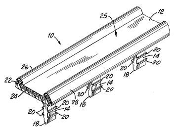
Referring now to the drawings, Fig. 1 shows an
extruded molding trim 10 constructed according to the present
invention. The extruded molding trim 10 has a one piece
integral body member including a longitudinally extending upper
strip-like portion 12 and longitudinally spaced apart leg
portions 14 extending perpendicularly downwardly from the
underneath surface 16 of the upper strip-like portion 12, as
best shown in Fig. 2. The leg portions 14 are centrally
located along the undersurface 16. Each leg portion 14 having
a pointed free end 18, and numerous aligned pairs of pointed
projecting tabs 20 extending transversely outwardly in an
upward direction from opposite longitudinal sides of each leg
portion 14. Preferably, there are four pairs of tabs 20 on
each leg 14, which are spaced a predetermined distance from
both the end 18 of the leg portion 14 and from the undersurface
16 of the upper strip-like portion 12, as will be explained
below.
The upper strip-like portion 12 is preferably
transparent and encapsulates a metallic strip 22 therein, such
being well known in the art as discussed in U. S. Patent No.
3,730,577 to which reference may be made. The metallic strip
22 extends for the entire longitudinal length of the upper
strip-like portion 12 so that the upper strip-like portion 12
takes on the appearance of the metallic strip 22. Fox example,
if the metallic strip 22 ls chrome or has a silver metal-like
finish, then the upper strip-like portion 12 would have a metal
_12_
: ., ,. ,, . ,; . -
, . , , ,. ~ .
.. . .. .
appearance, such as found on automobiles and appliances.
Additionally, a plastic ribbon like strip 24 is disposed on the
central portion of the metallic strip 22 along the entire
longitudinal length thereof, and is also encapsulated within
the upper strip-like portion 12, preferably within a recess 25
formed therein. The ribbon-like strip 24 has a wood grain
finish so that the center recessed part of the upper strip-like
portion 12 has an appearance of wood.
Accordingly, the metallic strip 22 can be made in any
color or texture as desired to provide the upper strip-like
portion 12 with a particular decorative appearance. The
metallic strip 22 can be fabricated from a metalized mylar or
any other suitable material such as a chrome film, tin foil and
the like which is fed in during the extrusion process, as
mentioned below. If desired, the metallic strip 22 can be
fabricated from a stiff rigid material to strengthen the upper
strip-like portion 12. Preferably, the longitudinal outer
edges 26, 28 of the upper strip-like portion 12 are enlarged
and rounded to provide the recess 25 and a decorative
appearance of metal rods being disposed on opposite sides of a
wood strip which is created by the ribbon-like strip 24.
The extruded molding trim 10 is constructed from a
continuous extruded T-shaped strip 30 of thermoplastic
material, such as acrynitrile butadiene styrene commonly
referred to as ABS, as shown in Fig. 3. The extruded T-shaped
plastic strip 30 includes a first bar-like portion 32 which
forms the upper strip-like portion 12, and a transverse
perpendicular second bar-like portion 34 which is used to form
the leg portions 14. Accordingly, the first bar-portion 32 is
constructed in the same manner as mentioned above for the upper
strip-like portion 12, with the metallic strip 22 and the
ribbon-like strip 24 encapsulated therein during the extrusion
thereof.
The transverse second bar-like portion 34 is
constructed as a continuous longitudinal piece having the pairs
of pointed projecting tabs 20 formed as rib-like constructions
35 extending outwardly in an ùpward direction from opposite
sides thereof along the entire longitudinal length of the
transverse second bar-like portion 34, as shown in Fig. 3,
with the free end 18 thereof being pointed along its entire
longitudinal length. It is noted, that the extruded T-shaped
strip 30 can be extruded ~rom one materialr such as ABS
mentioned above, or can be formed by a twin extrusion where a
second additional material can be used to form the pointed
projecting ribs 35 to provide the tabs 20, such as a soft vinyl
material of low durometer, such as urethane, so that the
pointed projecting tabs 20 would be resilient and could easily
deformed in its function, as mentioned below. ;~
After the T-shaped strip 30 is extruded, the T-shaped
strip 30 passes through a notching station where the second bar- ~ -~
like portion 34 is notched at longitudinally spaced apart
intervals across its entire transverse length, including through
the pairs of ribs 35 thereon, from the underneath surface 16 of
the first bar-like portion 32 to the end 18 thereof, where the
14 _
2~
intervals are predetermined along the longitudinal length
thereof. The notched portions are removed to provide cut-
outs 36 in the second bar-like portion 34 to form the legs 14, as
shown in Fig. 4.
Fig. 5 shows an example of extruded molding trim 40
constructed in the same manner as mentioned above to provide
the upper strip-like portion 12 and spaced apart leg portions
14. The extruded molding trim 40 is cut to a particular .pa
length, and is bent at points 42, 44 so that the two upposite
end portions 46, 48 are disposed parallel to each other and
the intermediate portion 50 is inclined. Accordingly, the `~-
extruded molding trim 40 has a particular configuration for
attachment to a particular molding or part~ as explained below.
Pig. 6 shows an automobile interior door part or ~`
panel 52 fabricated from a plastic foam-like material 54 having
a plastic outer cover 56 and a plastic inner cover 58 thereon,
where the door panel 52 to some degree is deformable, as ~`
indicated below. A recess 60 is formed therein to receive the
extruded molding trim 40, an intermediate portion 62 of the
door panel 52 is inclined in the same manner as the
intermediate portion 50 of the extruded molding trim 40 to
provide a particular design thereto. Numerous slots 64 are
provided through the base of the recess 60 to receive the leg
portions 14 of the extruded molding trim 40, there being as
many slots 64 as there are leg portions 14. The slots 64 are
approximately the same size as the thickness of the leg
portions 14, the slots 64 being only slightly larger to provide
,: . . . " ,. . .
: , .,
, ..
the proper clearance for the leg portions 14. However, the
distance between the tips of each pair of tabs 20 is larger
than the width of the slots 64, as explained below.
Accordingly, in the assembly, the leg portions 14 of
the extruded mol~ing trim 40 are placed into the recess 60 so
that end 18 of each of the leg portions 14 is aligned with
its associated slot 64. The extruded molding trim 40 is then
pushed into the recess 60, forcing the leg portions 14 through
the slots 64, where the pointed free ends 18 of the legs 14 are
used as a pilot to guide the leg portions 14 into and through
the door panel 52.
Once the extruded molding trim 40 is properly
seated within the recess 60, one pair of tabs 20 will catch
or hook behind the inner cnver 58, as best shown in Figs.
7 and 8. It is noted, that the door panel 52 does not have
a uniform thickness because the foam~like material 54 can -~
vary in thickness during the manufacture thereof. Thus, as
shown in Fig. 7, the second pair of tabs 20 from the end 18
catch behind the inner cover 58, while as shown in Fig. ~-
8, the first pair of tabs 20 from the end 18 catch behind
the inner cover 58. Thus, the extruded molding trim!40 is
easily attached to the door panel 52 where the numerous
pairs of tabs 20 on each of the leg portions 14 compensates
for any varying or non-uniform thickness of the door panel 52.
Though one example has been shown above~ it is
understood that the extruded molding trim of the present
invention can be attached to many different types of moldings,
panels, parts and the like which are fabricated from many
different types of material, while further examples are set
_16_
-
forth below. In the above example, the tabs 20 are fabricated
from a rigid material for insertion through the smaller sized
slots 64, and the material of the door panel 52 is fabricated
from a resilient deformable material so that when the tabs 20
are passing through the smaller sized slots 64, the walls of
the slots 64 in the door panel 52 deform to allow the tabs 20
to pass therethrough.
~ owever, should the extruded molding tri~ be trim
be attached to a molding, panel or part fabricated from a rigid
material, such as rigid plastic or sheet metal, it has been
found that such rigid material can shear off some of the tabs
20 when the leg portions 14 are being forced into the slots.
Therefore, in such cases, the tabs 20 would be fabricated from
a soft vinyl material, such as urethane, as indicated above, so
that the tabs 20 would be resilient and deform rather than
being sheared off, examples thereof being described below.
Thus, if the receiving part or member is fabricated from a
resilient deformable material, the tabs 20 can be fabricated
from a rigid material. However, should the receiving part or
member be fabricated from a rigid material, then the tabs 20
should be fabricated from a resilient deformable material.
Figs. 9 and 10 show a modified extruded molding trim
70 having a longitudinally extending upper strip-like portion
72 and the spaced apart leg portions 14 extending
perpendicularly downwardly from a center portion of the
underneath surface 74 of the upper strip-like portion 72, as
best shown in Fig. 10. The leg portions 14 are constructed in
~ ~ 9 ~
the same manner as mentioned above, having a pointed free end
18, and pairs of pointed projecting tabs 20 extending outwardly
in a slightly upward direction towards the upper strip-like
portion 72 from opposite side of each leg portion 14. In this
case, there are five pairs of tabs 20 on each leg portion 14,
with one pair of tabs 20 being disposed adjacent to the end 18.
-18-
The upper strip-like portion 72 has longitudinally
extending grooves 76 in its upper surface. Preferably, there
are four grooves 76. It is noted, that the grooves 76 provide
a non-skid upper surface on the upper strip-like portion 72.
Accordingly, the upper strip-like portion 72 can be opaque and
can be made in any desired color or texture, or can be
transparent and include the metallic strip 22 and/or ribbon~
like plastic strip 24 encapsulated therein to provide a
particular decorative appearance as mentioned above.
Fig. 11 shows a further modified extruded molding
trim 80 having a longitudinally extending upper strip-like
portion 82 and longitudinally spaced apart leg portions 84
extending perpendicularly downwardly from an approximate center
portion of the underneath surface 86 of the upper strip-like
portion 82. The leg portions 84 are constructed in a similar
manner as the above-mentioned leg portions 14, the leg
portions 84 having a slightly pointed free end 88, and pairs
of elongated finger-like tabs 90, 91 extending outwardly in a
upward direction towards the upper strip-like portion 82 from
opposite sides of each leg portion 84. In this case, there are
two pairs of finger-like tabs 90, 91 on each leg portion 84,
the pairs of finger-like tabs 90, 91 being spaced from the end
88 and also from the upper strip-like portion 82.
Preferably, the upper strip-like portion 82 and the
leg portions 84 are fabricated from a rigid plastic material,
such as the above-mentioned ABS, where the finger-like tabs 90,
91 are fabricated from a resilient deformable plastic
--19--
material, such as the above-mentioned urethane, in order to
function as mentioned below~
One side edge of the upper strip-like portion is bent
downwardly to provide a longitudinally extending side flange
92. A longitudinal metallic strip 94 is disposed around the
side flange 94, where the metallic strip 94 can be fabricated
in the same manner as the above-mentioned metallic strip 22,
being metal, a chrome film, tin foil, metalized mylar and the
like. Accordingly, a longitudinal protective transparent
plastic strip 96 is disposed over the metallic strip 94 to
provide a metal appearance as described above. Preferably, the
upper strip-like portion 82 is opaque and is made in any
desired color or texture. Accordingly, the metallic strip 94
and the protective transparent plastic strip 96 can be extruded
together with the upper strip-like portion 82 and leg portions
84t or can be securely mounted onto the side flange 92 after
the extrusion thereof.
As shown in Fig. 11, the extruded molding trim 80 is
attached to a plastic molding or part 98 of an automobile or
appliance, such as a refrigerator, dishwashing machine and the
like. The part 98 is preferably fabricated from !a rigid
plastic material, and includes a longitudinally extending step
100 on one side thereof to snugly receive the side flange 92,
and the metallic strip 94 and protec~ive transparent plastic
strip 96 thereon, to provide a decorative longitudinal side
edge for the part 98. Slots 102 are provided through the upper
portion of the part 98, the slots 102 being longitudinally
spaced apart by a predetermined distance and also being spaced
-20-
7 ~ ~
.
a predetermined distance from the longitudinally extending step100 to properly receive associated ones of the leg portions 84
therein.
In the assembly, the side flange 92 is lined up with the
step 100 and the pilot ends 88 of ~he leg portion 84 are
aligned up with their associated slots 102, and then the
extruded molding strip 80 is pushed towards the part 98 so that
the flange 92 fits into the step 100 and the leg portions 84
are inserted into their associated slots 102. Accordingly, as
each leg portion 84 is being inserted through its associated
slot 102, the pairs of finger-like tabs 90, 91 are deformed
and pushed inwardly towards the leg portion 84 by the rigid
plastic walls of the respective slot 102, as indicated by the
second pair of finger-like tabs 90 from the end 88 in Fig. 11.
Once the pair of finger-like tabs 91 exists the
opposite end of the respective slot 102 and is free of the
slot walls, the resilient material of the finger-like tabs 91
causes the finger-like tabs 91 to spring back to their normal
position, as shown by the first pair of finger-like tabs 91
from the end 88 in Fig. 11. The thickness of the part 98,
and therefore the depth of the slots 102, is predetermined so
that at least one of the pairs of finger-like tabs 90, 91 will
engage the inner surface 104 of a cut-away or stepped portion
106 in the part 98.
Thus, if a moderate force is used in àn attempt to remove
the extruded molding trim 80 from the part 98, the finger-like
tabs 91 of the first pair from the end 88 will engage the inner
surface 104 of the part 98, and will bend outwardly away from
-21-
: ~
2~
the leg portion 84 along the inner surface 104 to prevent the
removal of the extruded molding trim 80. However, if a
sufficiently strong force is used, the fin~er-like tabs 91 of
the first pair from the end 88 will first bend outwardly away
from the leg 84, as mentioned above, and then will continue to
bend downwardly, by the strong force~ towards the leg portion
84 so thàt the the finger-like tabs 91 of the extr~ded molding
trim 80 can be forced back into the slot 102 and removed from
the part 98, such as when it is necesssary to replace the
extruded molding trim 80.
It is noted, that the second pair of finger- like
tabs 90 in their deformed condition within the slot 102
provides additional restraining means to secure the extruded
moldlng trim 80 to the part 98. Furthermore, though only two
pairs of finger-like tabs 90, 91 are shown,~it is understood
that additional pairs of finger-like tabs can be added to the
leg portions 84 so that the extruded molding trim 80 can be
attached to a variety of parts having different thicknesses,
where one extruded molding trim 80 would fit all the parts.
Fig. 13 shows another modified extruded molding trim
110 having a longitudinally extending upper strip-like portion
112 and longitudinally spaced apart leg portions 114 extending
perpendicularly downwardly from the underneath surface 116 of
the upper strip-like portion 112 adjacent to the inner end
portion thereof. The leg portions 114 are constructed in a
similar manner as the above-mentioned leg portions 14, the leg
portions 114 having a curved or rounded free end 118, and only
2 ~
one pair of pointed tabs 120 extending outwardly from opposite
side~ of each leg portion 114. The pointed tabs 120 are
disposed at a predetermined intermediate position on the leg
portion 114, as set forth below.
As best shown in Fig. 14, each pointed tab 120
includes an upper vertical outer surface 122 horizontally
spaced from the leg portion 114~ which extends into a
downwardly inclined, outwardly extending outer surface 124.
The inclined outer surface 124 extends into an adjacent
downwardly inclined, inwardly extending outer surface 126,
which at the lower end thereof engages the leg portion 114.
Thus, the inclined outer surfaces 124, 126 form an outwardly
transversely extending point 128; as will be discussed below.
Preferably, the upper strip-like portion 112 and the
leg portions 114 are fabricated from a rigid plastic material,
such as the above-mentioned ABS, where the pointed tabs 120
are fabricated from a resilient deformable plastic material,
such as the above-mentioned urethane, in order to function as
mentioned below.
The outer side edge of the upper strip-like portion
112 is curved downwardly to provide a curved longitudinally
extending side flange 130. A longitudinal metallic strip 132
is disposed around the side flange 130, being fabricated and
functioning in the same manner as the above-mentioned metallic
: .
strip 94 shown in Fig. 11. Accordingly, a longitudinal - -
protective transparent plastic strip 134 is di~posed over the ~
.:
"
-23- -~
metallic strip 132 to function in the same manner as the above-
mentioned transparent plastic strip ~6 of Fig. 11 BO that a
metal appearance is provided as described above. Here again,
the upper strip-like portion 112 is preferably opaque and can
be made in any desired color or texture. As indicated above,
the metallic strip 132 and the protective transparent s~rip 134
can be extruded together with the upper strip-like portion 112
and leg portions 114, or can be mounted onto the side flange
130 after the extrusion thereof.
As shown in Fig. 13, the extruded molding trim 110 is
attached to a plastic molding or part 136 of an automobile or
appliance, such as a refrigerator, dishwashing machine and the
like. The part 136 is preferably fabricated from a rigid
plastic material, and incIudes a longitudinally extending side
edge 138 on the outer side thereof to receive thereon the side
flange 130, and the metal strip 132 and the protective
transparent strip 134 thereonr to provide a decorative
longitudinal side edge for the part 136. Slots 140 are
provided through the upper portion of the part 136, the slots
140 being longitudinally spaced apart by a predetermined
distance and also being spaced a predetermined distance from
the longitudinally extending side edge 138 to properly receive
associated ones of the leg portions 114 therein.
In the assembly, the side flange 130 is lined up with
the side edge 138 and the pilot ends 118 o`f the leg portions
114 are aligned with their associated slots 140, and then the
extruded molding trim 110 is pushed towards the part 136 so
that the side ~lange 130 engagingly slides against the side
--24--
, . ,. ,., ,.,, . : ,", , .. . .. , .- , .,. ,.. ;,., : .
edge 138 as the leg portions 114 are being inserted into
their associated slots 140. Accordingly, as each leg portion
114 is being inserted through its associated slot 140, the
point 128 of each pointed tab 120 is deformed and pushed
inwardly towards the leg portion 114 by the rigid plastic walls
of the respective slot 140 bearing against the inclined
surfaces 126. It is noted, that preferably the distance from
the vertical surface 122 of one tab 120 to the opposing
vertical surface 122 of the other tab 120 is less than the ~:
width of the slot 140 to provide a clearance fit therebetween.
Furthermore, the lower inwardly extending inclined surfaces
126 act as an insert guide which are the first surfaces to
engage the walls of the slot 140 during insertion of the leg
portions 114, and thus aid in deforming the points 128.
Once the points 128 of the tabs 120 exit the .
opposite end of the slot 140, and are free of the slot walls,
the resilient material of the tabs 120 causes the tabs 120 to
-
spring back to their normal condition, as shown in Fig. 13. :~:~
The thickness of the part 136, and therefore the depth of the
slots 140, is predetermined so that the underneath wall
~ .:
surface of the part 136 around the slot 140. engages the upper ~ ::
inclined outer surfaces 124 of the tabs 120. ~
.
Thus, if a moderate force is used in an attempt to :~
remove the extruded molding trim 110 from the part 136~ the
upper inclined outer surfaces 124 will contact the underneath ` ~:
wall surface of the part 136 around the slot 140 in a wedging : ~ `
engagement to prevent the removal of the extruded molding trim
110. However~ if a sufficiently strong force is used, the
-25-
~'
: ,: : .
r~
points 128 of the tabs 120 will again be deformed,in an
opposite direction, by the walls of the slots 140 so that the
tabs 120 of the extruded molding trim 110 can be forced back
into the slots 140 and removed from the part 136, such as when
it is necessary to replace the extruded molding trim 110.
It is noted, that even though only one pair of tabs
120 is shown in Figs. 13 and 14, it is understood that
additional pairs of tabs 120 can be added to the leg portions
114 so that the extruded molding trim 110 can be attached to a
variety of parts having different thicknesses, where one
extruded molding trim 110 would fit all the parts.
Fig 15 shows yet another modified extruded molding
trim 142 which is similar to the above extruded molding trim
110, except the molding trim 142 has been made wider to cover
both of the opposing longitudinally extending side edges of a
plastic molding or part 144 of an automobile or appliance,
such as a refrigerator, dishwashing machine and the like.
Accordingly, the extruded molding trim 142 includes a modified
longitudinally extending upper strip-like portion 145 and the
longitudinally spaced apart leg portions 114 extending
perpendicularly downwardly from an approximate centerl portion
of the underneath surface 146 of the upper strip-like portion
145. The leg portions 114 are constructed in the same manner
as mentioned above, having the curved or rounded free end 118,
and one pair of pointed tabs 120 extending outwardly from
opposite sides of each leg portion 114. Each pointed tab 120
also includes the upper vertical outer surface 122, the
-26-
,, ~ ,. .. . . . . . ..
2~
downwardly inclined outwardly extending outer surface 124, and
the downwardly inclined inwardly extending outer surface 126,
where the inclined outer surfaces 124, 126 form the outwardly
transversely extending point 128.
Here again, one outer side edge of the upper strip-
like portion 145 is curved downwardly to provide the curved
side flange 130, with the opposite outer side edge of the upper
strip-like portion 145 being bent downwardly to provide an
opposing side flange 148. A metallic strip 150 is disposed
around the side flange 130 and extends across the upper strip-
like portion 145 to be disposed around the opposite side flange
148, the metallic strip 150 being fabricated and functioning ~
in the same manner as the above-mentioned metallic strip `
132 shown in Fig. 13.
Accordingly, once again a protective transparent
plastic strip 152 is disposed over the metallic strip 150 to
~: :
function in the same manner as the above-mentioned transparent
plastic strip 134 of Fig. 13 so that a metal appearance is
provided as described above. Here again, the upper strip-like
portion 145 is preferably opaque and can be made in any desired
color or texture. As indicated above, the metallic strip 150
and the protective transparent strip 152 can be extruded
together with the upper strip-like portion 145 and the leg -
portions 114, or can be mounted onto the upper strip-like
portion 145 after the extrusion thereof. ~
:
-27-
~ .,. , ~, . :
Preferably~ as indicated above, the upper strip-like
portion 145 and the leg portions 114 are fabricated from a
rigid plastic material, such as the above-mentioned ABS, where
the pointed tabs 120 are fabricated from a resiliant deformable
plastic material, such as the above-mentioned urethane, in
order to function in a proper manner as indicated above. Here
again, the part 144 is preferably fabricated from a rigid
plastic material, and includes slots 154 extending through the
upper portion of the part 144, the slots 154 being
longitudinally spaced apart by a predetermined distance and
also being approximately centrally spaced between the
longitudinally extending opposing side edges 138 and 156 of the
part 144 to properly receive associated ones of the leg
portions 114 therein.
In the assembly, the side flange 130 is lined up with
the side edge 138, the side flange 148 is lined up with the
side edge 156, and the pilot ends 118 of leg portions 114 are
lined up with their associated slots 154, where the free end
118 of the legs 114 acts as a pilot to guide the leg portions
114 into the slots 154. The extruded molding trim 142 is then
pushed towards the part 144 so that the side flanges!130, 148
engagingly slide against their associated side edges 138, 156
as the leg portions 114 are being inserted into their
associated slots 154. Accordingly, during the insertion of the
leg portions 114, the point 128 of each pointed tab 120 is
deformed in the manner as mentioned above.
-28-
2 1 ~ 7
Once the points 128 of the pointed tabs 120 exit the
opposite end of the slots 140, the pointed tabs 120 spring
back to their normal condition, as shown in Fig. 15, for
engagement with the part 144 in the same manner as mentioned
above, where a furthr description thereof is not thought
necessary. It is noted, as indicated above, that a
sufficiently strong force can be used to deform the points
128 of the pointed tabs 120 to remove the extruded molding
trim 142 from the part 144, such as when it is necessary to
replace the extruded molding trim 142. It is further noted,
that additional pairs of tabs 120 can be added to each of the
leg portions 114, as indicated above, so that one extruded
molding trim 142 would fit a variety of parts having
different thicknesses.
It is noted, that each of the above embodiments
discloses a one piece longitudinally extending upper strip-
like portion having centrally located, longitudinally spaced
apart leg portions extending perpendicularly downwardly from
the upper strip-like portion, and aligned pairs of
projecting tabs extending outwardly from opposite
longitudinal sides of each leg portion. Accordingly, as set
forth below, Figs. 16 through 26 show modifications thereof,
which could be made to each of the above-mentioned
embodiments. However, by way of example, each of these
additional modifications are shown with respect to the
embodiment of Fig. 1, though it is understood that the same
additional embodiments could be made to any one of the
above-mentioned embodiments, where a showing thereof is not
thought necessary.
-29-
. ~ : ., `: ' `
.
: . , . ., , ,, . . " ~ .
-
2 ~
Furthermore, each of the embodiments shown in Fi~s. 16
through 26 has a one piece integral body member including a
longitudinally extending upper strip-like portion 12 similar
and functioning in substantially the same manner as the upper
strip~like portion 12 shown in Fig. 1. ~ccordingly, each of
the upper strip-like portions 12 in the embodiments of Figs.
16 through 26 is extruded from a plastic material or
materials as mentioned above and includes the undersurface 16
from which the leg portions extend downwardlyt the metallic
strip 22 therein where the above-mentioned plastic ribbon-
like strip 24 has been omitted for clarity but may be added
if desired, the longitudinally extending recess 25 to provide
the enlarged lontitudinal outer edges 26 and 28. The
additional embodiments will now be discussed below.
As shown in Fig. 16 and 17, the centrally located,
longitudinally spaced apart leg portions 14 of the modified
extruded molding trim 160 extend perpendicularly downwardly
from the underneath surface 16 of the upper strip-like
portion 12, with each leg portion 14 having a pointed free
end 18. ~owever, unlike above, each leg portion 14 has
numerous pointed projecting tabs 162 extending transversely
outwardly in an upward direction from one longitudinal side
of each leg portion 14, and additional pointed projecting
tabs 164 alternately extending transversely outwardly in an
upward direction from the opposite longitudinal side of each
leg portion 14 in a staggered arrangement, as best shown in
Fig. 17. As mentioned above, the }abs 162, 164 can be
fabricated from a riyid or resilient deformable plastic
material.
-30-
.9~i~
As shown in Figs. 18 and 19, the longitudinally spaced
apart leg portions 14 of the modified extruded molding trim
170 extends perpendicularly downwardly from the underneath
surface 16 of the upper strip-like portion 12. However,
unlike above, the numerous pointed projecting tabs 172 extend
transversely outwardly in an upward direction from only one
longitudinal side of each leg portion 14, as best shown in
Fig. 19. Here again, the tabs 172 can be fabricated from a
rigid or resilient deformable plastic material
Figs. 20 through 26 show further modified embodiments ~ ~
having two longitudinal rows of leg portions 174, 176 ~;
extending perpendicularly downwardly from the underneath
surface 16 of the upper strip-like portion 12. The leg
portions 174 in one longitudinal row are transversely
spaced apart from the leg portions 176 in the other
longitudinal row, either in an aligned or staggered
arragement. Each of the leg portions 174, 176 has the
above-mentioned pointed free end 18 thereon. The double row
embodiments will now be discussed below.
Figs. 20 and 21 show the modified extruded molding trim
180 having associated pairs of the leg portions 174, 176 of
the two rows in transverse alignment with each other. Each
of the leg portions 174, 176 is substantially the same as ~
the leg portion 14 shown in Figs. 1 and 2, so that each leg ~ ~ `
portion 174, 176 includes the numerous aligned pairs of
pointed projecting tabs 20 extending transversely outwardly
in an upward direction from opposite longitudinal sides of
--31--
each leg portion 174, 176, as best shown in Fig. 21. As
indicated above, the tabs 20 can be fabricated from a rigid
or resilient deformable plastic material.
Figs. 22 and 23 show a modified extruded molding trim
190 which is similar to the above molding trim 180, except
the numerous pointed projecting tabs 172 extend transversely
outwardly in an upward direction from only one longitudinal
side of each leg portion 174, 176, in the same manner as the
tabs 172 of the extruded molding trim 170. Preferably, the
tabs 172 are disposed on the outer surfaces of the leg
portions 174, 176 facing away from each other. Furthermore,
as best shown in Fig. 23, the tabs 172 on the leg portion
174 in one row are in transverse alignment with associated
tabs 172 on the associated leg portion 176 in the other
row, where as mentioned above, associated pairs of the leg
portions 174, 176 are in transverse alignment with each
other. Once again, the tabs 172 can be fabricated from a
rigid or resilient deformable plastic material.
Figs. 24 and 25 show the modified extruded molding trim
200 which is substantially the same as the above-mentioned
extruded molding trim 190, except for the positionin~ of the
tabs 202, 204. As best shown in Fig. 25, the numerous
pointed upwardly projecting tabs 202 on the leg portion 174
in one row are alternately spaced with respect to the
numerous pointed upwardly projecting tàbs 204 on the
associated leg portion 176 in the other row in a staggered
arrangement, similar to the staggered arrangement of the
tabs 162, 164 of the extruded molding trim 160. Here again,
--32--
~ ` % ~ 9 '~ ~
pairs of the leg portions 174, 176 are in transverse
alignment with each other. Furthermore, the tabs 202,
204 can be fabricated from a rigid or resilient deformable
plastic material, as indicated above.
Fig. 26 shows a modified extruded molding trim 210 from
the underneath side thereof. The extruded molding trim 210 has
the leg portions 174, 176 extending perpendicularly outwardly
from the underneath surface 16 of the upper strip-like portion
12, where the end portions of the leg portions 174, 176 are not
shown for clarity thereof in order to be applicable to any of
the pro~ecting tab arrangements shown in Figs. 20 through 25.
However, instead of pairs of the leg portions 1~4, 176 being
transversely in alignment with each other, as mentioned above,
the leg portions 174 in one row of the extruded molding trim
210 are alternately spaced with respect to the leg portions 176
in the other row of the extruded molding trim 210 to provide a
spaced apart staggered arrangement therebetween. Accordingly,
the leg portions 174, 176 of the extruded molding trim 210 ~an
have any of the tab arrangements thereon which are shown in
Figs. 20 through 25.
Each leg portion on the above mentioned extruded molding
trims of the present invention was inserted into its own
associated slot or the hole provided in the molding so that
there was a slot or hole for each leg portion. Accordingly,
when the extruded molding trim has two rows~of associated pairs
of leg portions, with the leg portions of each pair being
in a transverse alignment with each other, such as the
above-mentioned extruded molding trim 190 shown in Figs.
-33-
2~9~
22 and 23, each associated aligned pai~ of the leg
portions 174, 176 can be inserted into a single slot or
hole. In this case, either the entire extruded molding
trim or just the leg portions thereof are fabricated from a
resilient flexible material to permit the aligned
associated leg portions of each of the pairs to be squeezed
together when being inserted through their respective slots
or holes, whereby the associated aligned leg portions spring
or spread apart back to a normal condition after the tabs
thereon exit from the slots or holes. The resilient
flexible material can be fabricated from various
thermoplastic materials and blends of thermoplastic
materials, such as ABS, urethane, rigid vinyl, flexible
vinyl, high impact styrene and the like. In addition to the
above-mentioned extruded molding trim 190, other types of
extruded molding trims having two rows of associated aligned
pairs of leg portions can also be inserted in the same above
manner, as shown for example below in Figs. 27-31.
Figs. 27-29 show a modified extruded molding trim 220
which functions in a similar manner to the above-mentioned
extruded molding trim 190. The extruded molding!trim 220
includes a longitudinally extending upper strip-like portion
222 provided with longitudinally extending grooves 224 in its
upper surface to function as a non-skid upper surface in the
same manner as the above-mentioned upper strip-like portion of
the extruded molding trim 70 shown in Figs. 9 and 10. Two
longitudinal rows of leg portions 226, 228 extend
-34-
. .
" .;,. . .. .. .
2 ~ 7 ~:
perpendicularly downwardly from the underneath surface
230 of the upper strip-like portion 222. The leg portions
226 in one longitudinal row are transversely spaced apart
from the leg portions 228 in the other longitudinal rowO
Associated pairs of the leg portions 226, 228 are in
transverse alignment with each other. As indicated above,
either the entire extruded molding trim 220 or just the leg
portions 226, 228 thereof are fabricated from a resilient
flexible plastic material, such as mentioned above, to permit
the leg portions 226, 228 to be squeezed together, as
mentioned below.
Each of the leg portions 226, 228 have a curved or
rounded free end 232, 234, respectively, and one pointed tab
236, 238, respectively, extending outwardly from an outer
side of each leg portion 226, 228, so that the tabs 236,
238 point outwardly away from each other. Each tab 236, 238
includes an outwardly inclined outer surface 240, 242
extending upwardly from the free end 232, 234,
respectively. The inclined outer surface 240, 242 extends
into an adjacent inwardly inclined, upwardly extending outer
surface 244, 246, respectively, where the upper end of the
inclined outer surface 244, 246 engages the leg portion 226,
228, respectively. Thus, the inclined outer surfaces 240,
244 and 242, 246 form an outwardly transversely extending
point 248, 250, respectively.
2~ 9~
As shown in Figs. 27-29, the molding 252 or the part
of the vehicle, appliance and the like has a thickness
substantially equal to the distance between the underneath
surface 230 of the upper strip-like portion 222 and the
upper ends of the inclined outer surace 244, 246. The
molding 252 can be fabricated from any suitable material,
such as metal, wood, plastic and the like. A
predetermined number of longitudinally spaced apart slots
or holes 254, preferably equal in number to the number of
pairs of aligned associated leg portions 226, 228 on the
extruded molding trim 220, are provided through the molding
252. Each slot or hole 254 receives one pair of aligned
associated leg portions 226, 228 therein, in the manner set
forth below. As best shown in Fig. 29, the transverse width
of each slot or hole 254 is slightly larger than the
distance between the outer side surfaces of the aligned
associated leg portions 226, 228, but the transverse hole
width is less than the distance between the points 248, 250
on the aligned associated leg portions 226, 228, for the
reasons set forth below.
As shown in Fig~ 27, the extruded molding trim 220 is
disposed above the molding 252 so that the free ends 232,
234 are aligned with an associated slot or hole 254, where
the free ends 232, 234 function as a pilot to guide the
aligned associated leg portions 226, 228 into the slot or
hole 254. As shown in Fig. 28, the extruded molding trim
220 is pushed downwardly so that the inclined outer surfaces
240, 242 engage the walls o~ the slot or hole 254, and thus
..
-36-
squeeze the aligned associated leg portions 226, 228
together to permit the entry thereof into the slot or hole
254. As shown in Fig. 29, once the tabs 236, 238 exit from
the slot or hole 254, the aligned associated leg portions
226, 228 spring or spread apart back to ~he normal condition
thereof due to the resilient flexible material thereof to
capture the molding 252 between the underneath surface 230
of the upper strip-like portion 222 and the upper end of the
inclined outer surfaces 244, 246, thus securing the extruded
molding trim 220 to the molding 252.
Thus, if a moderate force is used in an attempt to
remove the extruded molding trim 220 from the molding 252,
the upper inclined outer surfaces 244, 246 will contact the
underneath wall surface of the molding 252 around the slot
or hole 254 in a wedging engagement to prevent the removal
o~f the extruded molding trim 220. However, if a
sufficiently strong force is used, the walls of the slot or
hole 254 will engage the upper inclined outer surfaces 244,
246 to squeeze ~he aligned associated leg portions 226, 228
together so that the aligned associated leg portions 226,
228 can be removed from the slot~or hole 254, such as when
it is necessary to replace the extruded molding trim 220.
It is further noted, that the length of the leg portions
226, 228 can be made in any predetermined length
so that the tab-free portions thereof correspond to the
thickness of the molding in order to engage same as
indicated above.
-37-
2 ~
Accordingly, Figs. 30, and 31 show a further modified
extruded molding trim 260 which is similar to the above
mentioned extruded molding trim 22~, except the length of
the aligned associated leg portions 262, 264 has been
lengthened to provide for two pointed tabs 236, 238 on each
leg portion 262, 264, respectively, where the tabs 236,
238 have the same construction and function as mentioned
above. Accordingly, the additional tabs 236, 238 permit the
same extruded molding trim 260 to be used for moldings or
parts having different thicknesses, as set forth below.
As shown in Fig. 30, the extruded molding trim 260 is
secured to a molding 266 or the part of the vehicle,
appliance and the like. Due to the small thickness of the
molding 266, only the upper tabs 236, 238 function to secure
the extruded molding trim 260, in the manner set forth
above, when the aligned associated leg portions 262, 264 are
inserted through the slot or hole 268 in the molding 266.
It is noted, that the distance between the upper tabs 236,
238 and the upper strip-like portion 222, and also the
distance between the upper and lower tabs 236, 238, has been ;~-~
shortened with respect to the same distance on the above
mentioned extruded molding trim 220 to accomodate the
smaller thickness of the molding 266 relative to the above
mentioned molding 252.
Fig. 31 shows a molding 270 having a larger thickness ~;
than either of the above mentioned moldings 252, 266.
Accordingly, a smaller slot or hole 272 is made through
the bottom of the molding 270 to coact with the lower tabs
236, 238, and a larger slot, hole or groove 27~ is made
' ~,
-38-
~1997 ~
through the upper surface of the molding 270 to accomodate
the upper tabs 236, 238, where the upper larger slot, hole
or groove 274 is in communication with the lower slot or hole
272. The depth of the lower smaller slot or hole 272 is
substantially the same as the above mentioned slot or hole
268 in the molding 266, so that the walls of the lower
smaller slot or hole 272 are captured between the upper
and lower tabs 236, 238, in the manner indicated above, to
secure the extruded molding trim 260 to the molding 270.
The width of the upper larger slot, hole or groove 274 is
less than the width of the upper strip-like portion 222, but
is greater than the distance between the points 248, 250 of
the tabs 236, 238, so that the upper tabs 236, 238 are free
from engagement with the walls of the upper slot, hole or
groove 274. Obviously, if desired, additional tabs 236, 238 `~
can be provided on the leg portions 262, 264 in a like
manner.
Numerous alterations of the structures herein
discussed will suggest themselves to those skilled in the
art. However, it is to be understood that the present
disclosure relates to preferred embodiments of the invention -
which are for the purpose of illustration only, and are not
to be construed as limitations of the invention.
39
. ~ .
, ~ . . : ~ .