Language selection

Search

Patent 2102059 Summary

Third-party information liability

Some of the information on this Web page has been provided by external sources. The Government of Canada is not responsible for the accuracy, reliability or currency of the information supplied by external sources. Users wishing to rely upon this information should consult directly with the source of the information. Content provided by external sources is not subject to official languages, privacy and accessibility requirements.

Claims and Abstract availability

Any discrepancies in the text and image of the Claims and Abstract are due to differing posting times. Text of the Claims and Abstract are posted:

  • At the time the application is open to public inspection;
  • At the time of issue of the patent (grant).
(12) Patent Application: (11) CA 2102059
(54) English Title: SUBSTANCE KNEADER
(54) French Title: MALAXEUR
Status: Dead
Bibliographic Data
(51) International Patent Classification (IPC):
  • D21B 1/34 (2006.01)
  • B01F 7/08 (2006.01)
  • B01F 13/10 (2006.01)
(72) Inventors :
  • HENRICH, HANS (Germany)
(73) Owners :
  • J. M. VOITH G.M.B.H. (Germany)
(71) Applicants :
(74) Agent: MCCARTHY TETRAULT LLP
(74) Associate agent:
(45) Issued:
(22) Filed Date: 1993-10-29
(41) Open to Public Inspection: 1994-05-07
Availability of licence: N/A
(25) Language of filing: English

Patent Cooperation Treaty (PCT): No

(30) Application Priority Data:
Application No. Country/Territory Date
P 42 37 433.2 Germany 1992-11-06

Abstracts

English Abstract


ABSTRACT OF THE DISCLOSURE
A substance kneader, specifically for cellulose
fiber suspensions, with kneading elements arranged at the
periphery of a rotor encased in a housing. Two drum type
rotor parts and a rotor part disposed in between feature
a feed worm conveyor for each rotor part. In the area
between facing ends of the worm conveyors, and symmetric
to this area, are the inlet openings of the housing. On
the ends away from each other, of the rotor parts, are
the outlet openings of the housing. The outlet openings
are each coordinated with delivery worm conveyors having
with variable-RPM drive for control of throughput and/or
dwell time of the substance to be kneaded.


Claims

Note: Claims are shown in the official language in which they were submitted.


-5-
WHAT IS CLAIMED IS:
1. A substance kneader for fiber suspensions,
comprising:
a housing, said housing having an inlet opening and
having outlet openings;
a rotor encased in said housing, said rotor having a
periphery, said rotor comprising two drum type rotor
parts and a rotor part disposed between said drum type
rotor parts, said rotor part including a separate feed
worm conveyor associated with each of said drum type
rotor parts, said feed worm conveyors having mutually
facing ends and having opposite ends, said mutually
facing ends defining a feed worm conveyor area
therebetween, said inlet opening being disposed in said
feed worm conveyor area and being positioned in a
generally symmetrical arrangement relative to said facing
ends, one of said outlet openings being positioned at
each of the opposite ends of the feed worm conveyors, a
plurality of kneading elements arranged at the periphery
of said rotor; and
a delivery worm conveyor coordinated with each of
the outlet openings.
2. Kneader according to claim 1, wherein each of
the delivery worm conveyors includes a variable-RPM drive
for control of throughput and/or dwell time of the
substance to be kneaded.
3. Kneader according to claim 1, wherein the
housing has a lower area, and the outlet openings are
positioned in said lower area.
4. Kneader according to claim 1, wherein the
delivery worm conveyors are arranged transverse to the
axis of rotation of the rotor.


-6-
5. Kneader according to claim 1, wherein the rotor
parts with the kneading elements are arranged and
fashioned essentially symmetrically.
6. Kneader according to claim 1, further
comprising a feed worm conveyor arranged toward the inlet
opening transverse to the axis of rotation of the rotor.
7. Kneader according to claim 1, wherein the
outlet openings are fashioned as circular sectors.
8. Substance kneader for fiber suspensions, with
kneading elements arranged at the periphery of a rotor
encased in a housing, characterized by two drum type
rotor parts with a rotor part disposed in between and
featuring a feed worm conveyor for each rotor part, and
with, in the area of the mutually facing ends of the worm
conveyors, symmetrically to this area, the inlet opening
of the housing, and, at the ends of the rotor parts away
from each other, the outlet openings of the housing, with
delivery worm conveyors coordinated with each.


Description

Note: Descriptions are shown in the official language in which they were submitted.


`~ x


-
21020~ ~
--1--

Hans Henrich
SUBSTANCE KNEADER
BACKGROUND OF THE INVENTION
The invention concerns a substance kneader,
specifically for cellulose fiber suspensions. Such a
kneader is known from Paper Technology, July, 1973, pages
196 through 202, respectively, T 136 through T 142.
Such machines process fiber materials at
consistencies between generally 26 to 35% and at an
elevated temperature generated by a steam supply. A worm
conveyor i8 provided, which feeds the substance to the
kneader, and a compression worm immediately precedes the
kneading elements of the rotor. Concerned here are ~-
machines having a housing which on one end features an
inlet, and on the opposite end features an outlet.
When treating the substance, generally referred to
as fiber suspension, rather high pressures are required
so that relatively high axial forces occur on the rotor
and, thus, on their bearings. Of course, the treatment
must be such that all fiber ingredients will be affected
at maximum uniformity. Also required is an appropriately
long treatment time, which amounts to approximately 20 s. ~ ;
With machines of prior design, the treatment time ~;
for the individual fibers of a charge was essentially the
same. At very high throughputs, however, appreciable
difficulties arose in the design of the machine.
1 25 The problem underlying the invention is to provide a
kneader which enables high amounts of throughput also at
very high treatment pressures.
SUMMARY OF THE INVENTION
This problem is solved through the features of the
present invention.
A substance kneader, specifically for cellulose
fiber susp2nsions, has kneading elements arranged at the

2102~
z .

periphery of a rotor encased in a housing. Two drum type
rotor parts have a rotor part disposed in between
featuring a feed worm conveyor for each drum type rotor
part. In the area of the mutually facing ends of the
feed worm conveyors, and symmetrical to this area, is an
inlet opening of the housing. At the opposite ends of
the rotor parts aré outlet openings of the housing, with
delivery worm conveyors coordinated with each of the
outlet openings.
An exact setting of throughput amounts or, `~
specifically, of the treatment time of the fibers can be -~
accomplished through the delivery worm conveyors. The
essentially symmetrical design of the machine makes
bearing loads resulting from the axial forces of the
rotor very insignificant. As a result, all fibers will
be subjected to essentially the same specific expense of
effort.
8RIEF DESCRIPTION OF THE DRAWINGS
The invention will be illustrated hereafter with the
aid of the drawing figures. `
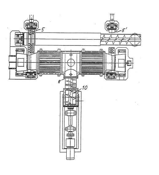
Fig. 1 shows a plan view of the inventional kneader,
partly in section;
Fig. 2 shows a partial axial section through the
kneader; and
Fig. 3 shows basically a cross section of the
machine.
DETAILED DESCRIPTION OF T~E INVENTION
Arranged centrally, or concentrically, in the
housing 1 is a rotor consisting of rotor parts 4, 4' and
6, with the rotor parts 4 and 4' supporting the kneading
elements 12. Also, the stator is fixed to housing 1.
The rotor part 6 essentially features a feed worm
conveyor 2, 2' for each of the rotor parts 4 and 4'
respectively. The inlet opening 8 is arranged

21020~
-3-

symmetrical to the feed worm conveyor region contained
between the rotor parts 4 and 4', and it is preceded by a i
feed worm conveyor 10. -;
The feed worm conveyors 2 and 2' effect a respective
compression of the fiber suspension, in order to be able
to maintain the respective pressure in the housing. -
Also contained in this housing region is a closable ~ -
opening 13 for the supply of steam and chemicals. The
delivery openings 15 and 15', respectively, at the axial
ends of the housin~, are arranged in its lower area in
the form of ring sectors, more axially than radially. In
this region, a delivery worm conveyor 5 and 5',
respectively, each extends transverse to the axis of
rotation of the rotor. The delivery worm conveyors may
each include a variable-RPM drive for control of
throughput and/or dwell time of the substance to be
kneaded.
The time of fiber passage through the housing is
e~sentially controlled by regulating the speed of
rotation of these worm conveyors. Resulting thereo~ is a
control of the level of compression and power consumption
in both kneading spaces. The delivery worm conveyors, of
course, run essentially in synchronism.
Additionally, the following is achieved through the
feed worm conveyor: a fiber suspension plug of rather
high consistency (as stated above) is created, enabling
the two feed worm conveyors 2 and 2' to then distribute
the entire throughput evenly to the two rotor parts 4 and
4', respectively, and the corresponding kneading spaces.
While this invention has been described as having a
preferred design, the present invention can be further
modified within the spirit and scope of this disclosure.
This application is therefore intended to cover any
variations, uses, or adaptations of the invention using

21020~
--4--

its general principles. Further, this application is
intended to cover such departures from the present ~.
disclosure as come within known or customary practice in : :
the art to which this invention pertains and which fall :~ ~
within the limits of the appended claims. ~:
Representative Drawing
A single figure which represents the drawing illustrating the invention.
Administrative Status

For a clearer understanding of the status of the application/patent presented on this page, the site Disclaimer , as well as the definitions for Patent , Administrative Status , Maintenance Fee  and Payment History  should be consulted.

Administrative Status

Title Date
Forecasted Issue Date Unavailable
(22) Filed 1993-10-29
(41) Open to Public Inspection 1994-05-07
Dead Application 2000-10-30

Abandonment History

Abandonment Date Reason Reinstatement Date
1999-10-29 FAILURE TO PAY APPLICATION MAINTENANCE FEE

Payment History

Fee Type Anniversary Year Due Date Amount Paid Paid Date
Application Fee $0.00 1993-10-29
Registration of a document - section 124 $0.00 1994-05-13
Maintenance Fee - Application - New Act 2 1995-10-30 $100.00 1995-10-04
Maintenance Fee - Application - New Act 3 1996-10-29 $100.00 1996-09-19
Maintenance Fee - Application - New Act 4 1997-10-29 $100.00 1997-09-26
Maintenance Fee - Application - New Act 5 1998-10-29 $150.00 1998-10-05
Owners on Record

Note: Records showing the ownership history in alphabetical order.

Current Owners on Record
J. M. VOITH G.M.B.H.
Past Owners on Record
HENRICH, HANS
Past Owners that do not appear in the "Owners on Record" listing will appear in other documentation within the application.
Documents

To view selected files, please enter reCAPTCHA code :


To view images, click a link in the Document Description column. To download the documents, select one or more checkboxes in the first column and then click the "Download Selected in PDF format (Zip Archive)" or the "Download Selected as Single PDF" button.

List of published and non-published patent-specific documents on the CPD .

If you have any difficulty accessing content, you can call the Client Service Centre at 1-866-997-1936 or send them an e-mail at CIPO Client Service Centre.


Document
Description 
Date
(yyyy-mm-dd) 
Number of pages   Size of Image (KB) 
Representative Drawing 1998-08-05 1 29
Cover Page 1994-05-07 1 85
Abstract 1994-05-07 1 59
Claims 1994-05-07 2 132
Drawings 1994-05-07 2 131
Office Letter 1997-01-16 1 13
Office Letter 1997-01-16 1 10
Description 1994-05-07 4 291
Fees 1997-09-26 1 34
Fees 1996-09-19 1 48
Fees 1995-10-04 1 44