Note: Descriptions are shown in the official language in which they were submitted.
~ ~ ~ 2 ~
Patent Specification
DEVICE FOR COOLING AND GRANULATING MOLTEN THERMOPLASTIC
STRANDS EMERGING FROM DES
The invention relates to a device for cooling and granulating molten
thermoplastic strands, which emerge from dies and which either drop
along the falling line starting at the dies or are guided in an operating
position through a coolant bath, freely stressed between guide rollers,
arranged in said bath and then are fed into granulator, where a precooling
device, which carries the strands emerging from the dies and takes them
to the coolant bath, is arranged in the region between the dies and the
coolant bath.
Such a device is known from the DE-PS 11 76 346. In this device betweenthe dies and the coolant bath there are cooling rollers, into which the
strands coming from the dies have to be threaded, in order to be guided
thereafter through the coolant bath. In the coolant bath the strands travel
through two pairs of deflecting rollers, which provide that the strands are
guided reliably through the coolant bath. After leaving the coolant bath, the
strands are then carried by a revolving conveyor belt, in order to then
travel into the inlet of the granulator. In this device the strands must be
threaded by hand, as customary with the use of such coolant baths, in the
region between the dies and the granulator into the organs guiding and
i ~ r
h ~ ~ h';~
ying the strands. This work is not only time-consuming, but it is also a
dangerous operation, since the responsible personnel for monitoring such a
device must reach into the hot strands. This is difficult, above all, when a
larger number of strands, e.g. 50 strands and more, has been produced due
; to the width of the space that the strands occupy. At every startup of the
device one has to wait until a qualitatively perfect material emerges from
the dies, a state which, according to experience, takes some time following
startup, during which the strands are guided first along their falling line
next to the device into a waste container. If the operating personnel
determines the quality of the emerging strands to be flawless, then a knife~
like tool has to be slid by hand over the dies, in order to produce a break in
the strands, after which then the newly emerging strands are guided into
the coolant bath. The more strands issue from the dies, the more difficult
this operation is, so that with this rnanual manipulation only one portion of
the dies can be stripped off in the described manner, so that the strands
emerging from the other dies continue to fall into the waste container.
' , : . -
In addition, a device for cooling molten thermoplastic strands emerging
from dies is known from the DE-AS 22 30 187; in said device the strands
are guided to a pair of conveyor belts, by means of which the strands and
the conveyor belts are guided in a meandering guide through a coolant
bath.
urthermore, it is known from the DE-AS 12 95 176 to cool the strands
emerging from the dies in a coolant bath, in which the strands are caught
by a collecting pan, before the strands are fed into a granulator. The
collecting pan is slid along a slideway, whereby the strands are supposed
to catch apparently in an intercepting slot of the collecting pan. They are
taken along by the displaced collecting pan and thus pulled out of the
coolant until they get to the granulator. To thread the granulator, the
strands are cut off upstream of the collecting pan, so that a quantity of
plastic, guided beforehand into the collecting pan, remains first in said pan
and has to be removed for the next working step.
The invention is based on the problem of automating the threading
operation of the strands in such a manner that it is ensured that the entire
number of delivered strands can always enter with their forward ends
simultaneously into the granulator.
This problem is solved according to the invention by disposing behind the
precooling device for a clamping grasp of the forward ends of the strands a
gripping device, which guides the forward ends of the strands -- after the
strands have been jointly separated by means of a separator moveable
through the falling line of the strands -- along a guiding rail running
through the region of the coolant bath as far as the granulator.
::. ::
'. e gripping device is always offered in this manner the forward ends of
the strands that are produced after separating the strands by means of the
moveable separator, so that the forward ends of the strands are
subsequently threaded by means of the gripping device moved along the
guiding rail virtually without mutually offsetting the forward ends of the
strands in the longitudinal direction. Thus, the gripping device guided
along the guiding rail can reliably grasp the forward ends of the strands,
which are cut by the separator and from which every opportunity has
been taken in the gripping device to stick to the neighboring strands. Thus,
the forward ends of a flawless material reach in essence simultaneously
the granulator, so that said granulator can immediately cut the strands into
pellets of high value quality. In contrast, when a larger number of strands
are threaded by hand, the forward ends of the strands always form lumps,
after which the strands continue to flow in more or less stuck together for
some time. The granulator cannot cut perfect pellets from this mass of
delivered material, since pellets can be cut only from clean single strands.
The gripping device is provided expediently with opposed clamping rollers
to grip the forward ends of the strands, since said gripping device can also
exert a feeding motion on the strands.
The guiding rail and thus the gripping device can be guided as far as
immediately in front of the granulator, from where then the strands can
travel directly into the inlet of the granulator. However, it is also possible
,
4 ~ ~
.'' -,
,, ~ ~ .
~ v~L ~!~
~ let the guiding rail terminate in an end position, in which the rollers are
set into motion in the sense of a feed motion, until the strands are grasped
by the granulator. This kind of feed of the strands to the granulator has
the advantage that it is not necessary to bring the gripping device close up
to the granulator, a feature that in the case of irregularities in the position
of the individual strands in the gripping device could lead to single strands
not being grasped at all by the granulator. If, however, the gripping device
with its rollers can feed the strands into the granulator from a specific
distance up stream of the granulator, and in particular due to the
corresponding rotation of the rollers, then this method of operating the
gripping device guarantees that in the final analysis all of the strands can
also be grasped reliably by the granulator.
.,
With precooling the goal of designing the precooling device as a discharge
channel, which is fed with the coolant and which is arranged underneath the
dies to catch the strands, can be achieved. This discharge channel is a simple
component, which can be accessed from the top and on which the strands
falling from the dies are automatically oriented subject to the influence of
the coolant stream flowing over the discharge channel. In the region of the
discharge channel the strands are adequately cooled~ in order to be then
grasped as forward ends by the gripping device without any significant
deformation.
~ e discharge channel can be combined in a manner that makes sense
from a technological point of view with the separator, namely by rendering
the discharge channel moveable along a carriage guide and by assigning to
it the separator, which while moving the front side of the discharge
channel grasps and separates the strands through the falling line of the
strands into the operating position.
With such a moveable discharge channel it can be achieved that in its
external operating position said discharge channel lets the strands in the
falling line fall into a waste container, a process that is necessary, as
explained above, during startup of the system, whereupon then when the
strands of flawless material emerge, the discharge channel can be slid with
its front side through the falling line of the strands, whereby the separator
allocated to it grasps and jointly separates the strands.
It should also be pointed out that such a relatively short discharge channel
with a separator interacting with another discharge channel is known from
the DE-PS 32 05 052.
The guiding rail runs expediently through the coolant bath and around the
guide rollers, so that if the gripping device runs in an analogous manner,
the strands grasped by said gripping device are guided through the coolant
bath and thus also around the guide rollers, thus completing the automatic
. .
:,
~3
' ~ & '? ~
u eading operation. At the same time, however, the guiding rail must run
through corresponding curves in the region of the inlet and the outlet to
the coolant bath. However, it is also possible to design the guiding rail in
essence linearly. To this end, the guide rollers can be moved in such a
manner that they can be lifted out of the coolant bath and lowered into
said bath, and that the guiding rail runs between coolant bath and the
elevated position of the guide rollers, whereby upon reaching the end
position the guide rollers are moved into the lowered position by means of
the gripping device.
..
In the design of the guiding rail, the strands are first moved freely
suspended over the coolant bath, whereupon the previously elevated guide
rollers, below which the guiding rail runs, are lowered, whereby they dip
the strands into the coolant bath. Then the strands continue to run around
the guide rollers through the coolant bath.
Embodiments of the invention are shown in the drawings.
Figures la and b are side views of the device -- and in particular in Figure
la depicted in the operating position in which the strands travel into the
granulator, and in Figure lb depicted in the startup position, in which the
strands first fall from thc dies along the falling line.
'~
7 ::
l.gure 2 is a top view of the device according to Figure la.
Figure 3 depicts a modification of the device according to Figure 1 with the
guiding rail running above the coolant bath.
Figure 4 depicts the gripping device in the closed position.
Figure 5 depicts the gripping device in the opened position.
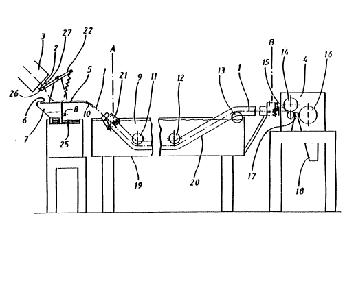
The device shown in Figure 1 receives the strands 1 from the die head 3,
which exhibits the dies 2 and from which the strands 1 emerge in the
molten state. In the operating position, which is shown in Figure la and in
which the strands 1 enter into the granulator 4, the strands 1 fall on the
precooling device, which is designed as a discharge channel 5 and on
whose left end an overflow 6 is disposed for the entry of cooling water,
which flows from the water tank 7 into the ovefflow 6. The water tank 7
receives the cooling water by way of the inlet port 8. The cooling water
flowing through the overflow 5 guides the strands 1 over the discharge
channel 5 into the coolant bath 9. The required deflection of the strands 1
from the horizontally arranged discharge channel 5 into the sloped
direction of the subsequent course of the strands 1 into the coolant bath 9
is accomplished by means of a rounding off 10 at the end of the discharge
channel 5. The strands 1 are deflected by means of the guide rollers 11
h ~i ~ ;'J ;~
~ 1 12 in the coolant bath 9 and subsequently guided out of the coolant
bath 9 by means of the deflecting roller 13. After the deflection of the
; strands 1 around the deflecting roller 13 the strands 1 travel directly into
the granulator 4. Here a standard design is shown as the granulator, which
contains the two feed rollers 14 and 15 and the rotor 16 with the
stationary knife 17. The pellets cut off from the supplied strands 1 by
means of the rotor 16 fall through the outlet chute 18 from the granulator
4 for further processing or use.
In the device illustrated the strands 1 are cooled in two steps, namely first
by means of the discharge channel 5, which serves as the precooling device
and on which the strands are cooled to the point they are at least
externally solidified. Along its additional run through the coolant bath 9 -~
the strands 1 are then cooled to the point that they can be pelletized in the
customary manner by means of the granulator 4. The coolant bath 9 is the
vat 19, in which is located the water as coolant, whose temperature is set
in such a manner that the degree of cooling the strands 1 that is necessary -~
for subsequently pelletizing is obtained.
''~
The device shown in Figure la exhibits for the automatic threading of the ~ ;~
forward ends of the strands 1 the guiding rail 20, which serves to guide the
gripping device 21, which can run by itself from position A, shown by the
dash-dotted line, into position B. While the guiding rail 20 travels from
`
~;L ~
~sition A into position B, the gripping device 21 takes the forward ends of
the strands that it has grasped along the guiding rail 20, whereby the strands
taken along by the gripping device 21 loop around the two guide rollers 11
and 12 in the position shown in Figure la and are deflected by the deflecting
roller 13, until they arrive finally directly upstream of the inlet of the
granulator 4.
The gripping device 21 grasps the forward ends of the strands fed to it in the
manner explained in detail in connection with Figures 4 and 5. To feed at this
stage altogether the strands 1, which emerge from the die head 3 and which
at the instant they are grasped by the gripping device 21 lie along the dash-
dotted line D in Figure 2 (reference numeral 28), to the gripping device 21,
there is a separator 22 that in Figure la is shown in a position in which it is
located after complete separation of the strands 1.
.,
The shape and function of the separator 22 are explained in detail in the ~:
following. -
Figure lb shows the separator 22 in its position prior to separating the
strands 1. The separator 22 is designed as a lever, which is mounted on the
axis of rotation 23. The axis of rotation 23 is attached to the support 24,
which is mounted on the discharge channel 5. The discharge channel S and
the wator tanlc 7 can be moved baclc and forth in the horizontal direction
,~';~':
. ~:
~IPr: ' : ,
2 i ~
I.leans of the carriage guide 25 . In the drawing according to Figure 1 b the
separator 22 and the related components are in the right displacement
position of the carriage guide 25, in which the strands la emerge from the
dies 2 as waste and fall downward along their falling line, e.g. into an
arbitrary waste container (not illustrated). At the same time it involves the
starting-up position, in which after putting the die head 3 into operation firstdegraded material emerges that cannot travel into the device, shown Figure
la, because it falls along the falling line.
If it is then determined that material whose quality is perfect is emerging
~rom the dies 2, the water tank with the discharge channel 5 and thus the
separator 22 are moved to the left, thus taking the separator 22 over the
support 24. The left end of the separator 22 has a knife 26, which during ;
this movement appears on the surface 27 of the dies 2, combined into a set -
of dies, and slides over the surface 27 as the carriage guide 2S continues to
move along its course until the knife 26 arrives in the position shown in
Figures la. On this path the knife 26 cuts the strands, emerging from the :dies 2, so that the forward ends of the strands emerging from the dies at
this stage (see reference numeral 28 in Figure 2) travel on the discharge
channel 5 and are advanced over said discharge channel with its rounding ;~
off 10 in the direction of the gripping device 21. This is accomplished by
means of the coolant, which flows out of the overflow 6 and which floods
the forward ends 28 of the strands uniformly over the discharge channel 5
in the direction of the coolant bath 9.
11
,.'' 2 ~
e separating operation of the strands and their collection by the discharge
channel 5 are described in detail in the aforementioned DE-PS 32 05 052.
By means of this well-known measure of separating the strands 1, forward
ends 28 of strands (see Figure 2) that lie on the same level are produced in
the direction of movement of the strands, a feature that is utilized to feed to
the gripping device 21 forward ends that can be grasped all at once and
that are grasped almost immediately behind their cut point (see Figure 2),
without any larger lengths of strands that could have a negative effect on
the above described threading operation of the strands existing in front of
the grasping point.
~ ~:
Figure 2 is a top view of the device according to Figure la, wherein in the
region of the discharge channel the separator 22 with its other components
is omitted for reasons owing to a better overview. Shown are three strands
1 that lie side-by-side and that run from the discharge channel 5 through
the gripping device 21 into the coolant bath 9 and into the granulator 4. It
must be pointed out that normally with such a device a significantly larger
number of strands that lie side-by-side are processed, e.g. 50 and more
strands, so that the total number of strands 1 extend over a relatively
wide area, in which then the forward ends 28 of the strands have to be
grasped simultaneously by the gripping device 21.
~.
12
..
.
} Oure 2 also shows the drive motor 29, which serves for the movement of
a drive member, which runs in the guiding rail 20, for exarnple a chain, by
means of which the gripping device 21 is moved out of position A into
position B and back.
Figure 3 shows a modification of the design of the device according to
Figures 1 and 2. This modification consists of the guiding rail 30 extending
linearly, and in particular above the coolant bath 9, so that, while the
gripping device 21 is traveling from position A into position B, the strands
1, which sag slightly, are pulled first above the vat 19. To enable this
guiding of the strands 1 that occurs first, the guide rollers 31 and 32 ~-~
(corresponding to guide rollers 11 and 12 according to Figure 1) ean be
lifted out of the coolant bath, as shown by means of the dash-dotted ~ ~:
position of the guide rollers 31 and 32. The guide rollers 31 and 32 hang
on hydraulically operated feeders 33 and 34, which are suspended from
the support 35. The support 35 is mounted on pillars 36 and 37. :~:
'~
To move the gripping device 21 out of position A into position B, the guide
rollers 31 and 32 are moved into the elevated position, shown by the
dash-dotted line, so that the requisite space for the strands 1 moved by
the gripping device 21 is available. After the gripping device 21 has
reached position B, the guide rollers 31 and 32 are lowered into the coolant
bath 9, whereby the strands 1 are also dipped into the coolant bath 9,` -~
l ~ . ~ . . , ;, . ;. .~.. - . , :
.`~
.lereupon during the further course of processing the strands 1 the
deflecting rollers 31 and 32 guide the strands 1 in the same manner as
explained above in connection with Figure 1.
With respect to the other function of the components of the device
according to Figure 3~ reference is made to the explanations for Figures la
and b.
Figures 4 and 5 are described next to explain the function of the gripping
device 21.
According to Figure 4, which is a sectional view along line IV-IV from
Figure 3~ the gripping device 21 comprises an angle support 38~ to which
the two guide rollers 39 are attached that envelop a track 40 attached in
the guiding rail 30 and thus give the gripping device 21 a reliable
mounting with moveability in the longitudinal direction of the guiding rail
30~ Furthermore, two clamping rollers 41 and 42 are attached to the angle ~-
support 38; of said clamping rollers the clamping roller 42 can be moved
into the clamping position shown in Figure 4 or into the open position :
shown in Figure 5. To this end, the clamping roller 42 sits on the arm 43,
which is swivel-mounted on the angle support 38 and which, as Figure 3
shows, mo~es by means of its swiveling relative to the angle support 38
the clamping roller 42 either away from the clamping roller 41 (see Figure
2,' ~ 6
~ and pushes it in the direction of the clamping roller 41 (see Figure 4).
Moreover, the simultaneous guiding of both clamping rollers 41 and 42
into the clamping position shown in Figure 4 can be facilitated by means of
a suitable spring, which pulls together the two clamping rollers 41 and 42.
The two clamping rollers 41 and 42 are opened, according to the drawing
in Figure 5, in position A by means of the cam 44, on which the clamping :
roller 42 runs up when the gripping device 21 is returned into position A,
thus lifting said clamping roller 4Z from the clamping roller 41 by means
of the arm 43.
.~ ~
When the gripping device 21 is led along the guiding rail 30 to position B,
the clamping roller 42 touches down on the carrier track 45, which carries
a friction lining that provides that upon further movement of the gripping
device 21 in the direction of the granulator 4 the clamping roller 42 is set
rotating, and especially with such a direction of rotation that the strands 1,
which are clamped between the clamping roller 42 and 41 are advanced. -
This feeding movement continues until at the end of the carrier rail 45 the
clamping roller 42 strikes the cam 46, which, like the cam 44, provides
that the clamping roller 42 is lifted from the clamping roller 41, thus
releasing the previously clamped strand 1 (position C). The strands 1 are :
then advanced due to the forced rotation of the clamping roller 42 so far
that they move into the granulator 4 and are grasped by the feed rollers
14 and 15.
.
. ,
~?: ~ - ~
~ 2 ~
ures 4 and 5 also show the chain 47, which runs in the guiding rail 30
and which is driven by the drive motor 29 shown in Figure 2. The chain is
attached to the angle support 38. It is self-contained. The region of the
chain 27 that is opposite the attachment point hangs freely in the guiding
rail 30 or can be guided in said guiding rail by the carrier rollers.
For automatic threading of the forward ends 28 of the strands, said ends
are grasped by the two clamping rollers 41 and 42 in position A and
clamped, whereupon the gripping device 21 is guided into position B,
where the clamping of the strands 1 is eliminated, as described above.
The strands 1 can then travel into the granulator 4 and are pelletized by
it. During the pelletizing operation, the gripping device 21 remains in
position B or the adjacent position C (opened clamping rollers 41 and
42), since in this position the gripping device 21 does not interfere with
the course of the strands 1. If then for some reason it is necessary to
start the device again, the gripping device 21 is moved into position A
by means of the drive motor 29, whereupon then the device is started
up and the forward ends 28 of the strands are taken oven in the manner
described above and thus a new pelletizing operation starts.
1 6