Note: Descriptions are shown in the official language in which they were submitted.
2102254
ENERGY ABSORBING MOUNTING SYSTEMS FOR -
MOTOR VEHICLE WINDOWS
FIELD OF INVENTION
Energy Absorbing Mounting Systems for Motor Vehicle windows, ~ `
particularly for automobiles, that are safe for vehicle impact collisions are described. -
,
DESCRIPTION OF PROBLEM
Side and rear windows in motor vehicles are currently manufactured from
float glass that has been tempered. Tempering of glass places the two outer surfaces
of the glass into compression. Therefore when the glass is impacted it will shatter - --
into very small pieces. Tempered glass has replaced annealed glass in window
openings of motor vehicles. Annealed glass breaks into large dagger-like shards that ~ -
can easily lacerate and seriously injure a vehicle occupant. While tempered glass
has reduced lacerations, there remain several problems.
Tempered glass can cause laceration of an occupant because the small
fragments have very sharp edges; and if a tempered glass window breaks, pieces of
glass remain embedded in the edge of the window. This may cause parts of a
person's body to be raked along the edge of the window and result in serious
lacerations. i
Since tempered glass will shatter, it does not offer the vehicle occupant any `
protection from being ejected from the passenger compartment. If the vehicle is
impacted from the side, the passenger could be partly or wholly ejected out through ~ ~-
`
the window opening. If the vehicle begins to tumble in a rollover then the
2102254
occupant could be partially or fully ejected and could incur a serious or a fatal injury
once parts of the body are outside the vehicle.
Some work is known that attempts to improve the laceration and ~ ~
containment deficiency of tempered glass. Windshields, for example, are composed - -
of two layers of glass separated with a thin layer of plastic. The inner layer, made of
poly (vinyl butyral), holds the broken glass together upon vehicular impact. A
further refinement is found in that a second plastic layer is applied to the inner
surface of the window.
A moveable window design with a combination of an inner plastic layer and
an outer glass layer is known. This window is intended to contain the occupant
within the vehicle during a side impact collision. This is accomplished by a multi~
part structure composed of a plastic frame that moves up and down in a special track
design. The plastic frame has an edge in the shape of a "T," and acts to sandwich ~ ~
together the outer glass layer and the inner plastic layer. The disadvantages are that -
the inner plastic layer is prone to scratching, reducing driver visibility, and the
frame adds weight to the glazing skucture. -
A few inventions have been described using thermoplastic window for motor
vehicles. U.S. Pat. No. 4,635,420 describes an acrylic window material that is
ulkasonically welded to a plastic gaslcet. A safety feature is disdosed where grooves
or notches are placed inward from the edge of the acrylic window to facilitate
breakaway zones. Two disadvantages in this type of gasket installation are that it is
not commonly used by original equipment manufacturers and is not economical to
manufacture. Another patent describes a synthetic resin window for a vehicle that
has a frame or gasket molded from the same synthetic resin material. This windowis lightweight yet does not incorporate any feature that makes it safe during a
potential side impact collision.
2~022~4 ~
It would be desirable to use a monolithic glazing structure composed of a
thermoplastic resin with a window mounting system that can reduce lacerations,
produce no head injuries and provide occupant containment. A further beneQt
may be from a reduction in weight of the window structure.
BRIEF DESCRIPTION OF THE DRAWINGS
FIG. 1 is a perspective view of a side window module for an automotive
vehicle according to one preferred embodiment of the invention.
FIG. 2 is a fragmentary cross-sectional view of an embodiment of a sheet of
thermoplastic glazing material.
FIG. 3 is a schematic representation showing other variations in the
embodiment of FIG. 2.
FIG. 4 is a perspective view of another embodiment of the invention, i.e., a
side window installation in a motor vehicle, using Reaction Injection Molded
(RIM). FIG. 5 shows a cross section of the window assembly with frame and
mounting bolt.
FIG. 5 is a section taken through the bottom of the side window in FIG. 4
showing a mounting bolt that attaches the window module to the vehicle chassis. ~ ~ ~
FIG. 6 is a perspective view of another embodiment of the invention ~ -
referring to moveable window installations in a vehicle door frame.
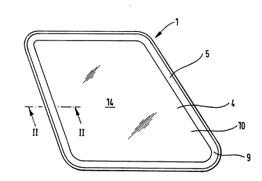
Referring now to FIG~. 1, 2, 3, 4, 5, and 6 there is shown a synthetic resin
window according to one embodiment of the present invention, which may be used
in an automotive vehicle. The window module is designated by reference numeral
1, and is made of an appropriate thermoplastic resin by means of an injection
molding or thermoforming process, as will be described hereinafter, and secured to a
relevant vehicle chassis panel 6 with a mounting system.
3 ~ ~
~.. .. . ..
.
210225~ ;
The window module 1 includes a window body portion 4 in the form of a
sheet of transparent or semi-transparent synthetic resin, such as polycarbonate resin,
acrylic resin or polyglutarimide resin, or the like. The window module 1 furtherincludes a frame portion 5 extending along the peripheral edge of the window body
portion 4. An abrasion resistant coating 10 covers the surfaces of the window body
portion 4. If there is not a molded frame portion 5, a pressure sensitive foam tape, :
or sealant, such as polyurethane, 16 can be used as hereinafter described. A notch or
groove 9 cut or molded into the window body portion 4 will enhance the formationof a breakaway zone 14.
In FIG. 2 and FIG. 3 embodiments, notches or other shaped grooves 9, can be
cut or molded into one or both sides of the synthetic resin glazing material. Some of
the possible shapes shown in FIG. 3 can be cut or molded into the synthetic resin
glazing materials as taught by U.S. Pat. No. 4,635,420. A double sided adhesive foam
strip 16 is adhered around the edge of the glazing material.
In FIG. 4 and FIG.5, a typical motor vehicle window aperture 8 is shown on
the rear side. The metal edge of the aperture, as part of the chassis panel 6, has bolt
holes 13.
FIG. 5 is a cross section of the window module 1 installed in a window
aperture 8. The thermoplastic window material 4 is encapsulated by a RIM
mounting frame 5. A mounting bolt 7 has its bolt head 18 embedded in the interior
facing section of the RIM 12. The mounting bolt attaches the window module 1 to
the motor vehicle chassis panel 6 using a threaded nut 15.
FIG. 6 shows a thermoplastic window 4 installed in a door 20. The frame 21 of
the upper portion of the door 28, holds the window material in a track 22. The track
acts to absorb energy of an impact and functionally allows the thermoplastic window - -
4 to travel up and down.
. . . ~
;,~ , ,;
4 ~ ~-
- -: -, ~ .
~ . ,, :. .
'.;" '"' ~' .''. '
2102251
SUMMARY OFINVENTION
We have designed several energy absorbing mounting systems which when
used in combination with transparent thermoplastic automobile windows produce
unexpected safety benefits such as no head injuries (HICl < 1000), lit~e or no
lacerations (Chamois Laceration Scale2 S 1) and enhanced occupant containment invehicle crashes. The window designs preferably use an abrasion resistant coated ~ `
thermoplastic with high modulus (i.e., above about 2.0 GPa). There are many
different mounting system designs that may be used to achieve this behavior and
some are described below.
Head Injury Criteria (HIC) from 49CFR 571.208:
1 t2 2.5
HIC = ¦adt (t2 - tl ) Eq. (1)
t -t ~l
where a = the resultant head acoeleration expressed as a multiple of g (the acceleration of
gravity),
where tl and t2 are any two points in time during the impact which are separated by not more
than a 36 millisecond time interval and
where t~ and t2 are selected so as to maximize Eq. (1).
If the HIC value is below 1000, then 49CFR 571208 states that the potential for head injury is
unlikely. If the HIC value is above 1000, then the potential for head injury is possible.
2Chamois Laceration Scale:
0 &perficial Cuts Pass .:
OuterLayerCuts Pass ...
2 InnerLayerCuts Fail
Refelence Eo~ iety of At~tomobYe Enf ineels paper Number ftfiol98 (198(i).
210225~
- .
The window body portion 4 can be attached to the vehide chassis panel 6 by
using a foam tape 16 with a pressure sensitive adhesive. The adhesive will bond the
foarn tape core to the window and the vehicle providing a weather seal. ~ -~
The combination of the thermoplastic window and a foam-based adhesive ~
tape allows the window to stretch out in the window opening in the plane of the ~ -
window yet not disengage or break at low to moderate head velocities. If there is an
impact to the window by a vehicle occupant the window will not break, nor will the
occupant receive any lacerations (as the window will not break), nor will the
occupant receive any head injury at low to moderate head velocities. Low to
moderate head velocities are velocities that could range from 0 to 32 kilometers per
hour. High head impact velocities are those velocities above about 32 kilometersper hour. The tape can be made strong enough to hold the window in place but canstretch to many times its original ~ickness and provide enhanced energy absorbing
characteAstics. If the window should break, due to a flaw in the design, then the
tape will let any broken pieces be safely retained in the window opening. If thewindow disengages, however, much of the kinetic energy of the impact will eithergo into ripping the tape apart (cohesive failure) or ripping the tape from the window
or frame ~adhesive failure). Once the broken pieces are pushed out away from the -
window opening, the tape rips itself and can not elastically pull the pieces back
towards the plane of the window aperture.
In combination with the use of tape 16, a notch or groove 9 can be cut,
machined or molded into the plastic glazing material 4. The groove or notch ~ ~ ,
molded or machined into the thermoplastic window inward from the edge will
enhance a breakaway zone 14. The notch or groove should be shallow enough so
that the plastic glazing does not pop-out at low to moderate head impact velocities,
for example, 0 to 32 kilometers per hour, and the plastic glazing should be designed
.,; : . - : ~::
- .
21022~4
~o that the plastic glazing does pop-out or break at high head impact velocities, for -
example, above 32 kilometers per hour. Various depths and various shapes of the
notdhes may be used to effectively release the plastic glazing fragments. At higher
head impact velocities, the plastic will break along the notch in a defined breakaway
zone and release the window from the edge. This will safely release any broken
fragments of the plastic glazing. In combination with the notch, the tape will let any
fragments safely hang down and away from the occupant, therefore, if the
breakaway zone does not behave as designed, the occupant is unlikely to receive any
injury to the head as will be shown in the examples hereinafter.
The window also can be attached to the window aperture in a motor vehicle
by using an automotive grade polyurethane sealant. The polyurethane will bond
the window to the vehicle and provide a weather seal.
In combination with the use of polyuremane, a notch or groove can be cut or
molded into the plastic glazing material. A groove or notch molded or madlined
into the thermoplastic window inward from the edge will enhance a safe release of
the window.
The combination of a thermoplastic window, polyurethane sealant, and
notched perimeter allows the window to stretch out of the window frame opening.
If there is an impact to the window by a vehide occupant, the window will not
break, nor will the occupant receive any lacerations since the window will not break,
nor will the occupant receive any head iniury at low to moderate head velocities.
The polyurethane is strong enough to hold the window in place, but can stretch to
several times its original thickness. If the window does disengage, much of kinetic
energy of the impact will go into breaking the thermoplastic along the notch. If the
window should break, due to a flaw in the design, then cracks in the thermoplastic
will propagate outwards towards the edge of the window and break along the notch.
210225~
rhe occupant does not receive any sPrious injury to the head as has been shown in
the examples.
The thermoplastic window 4 can also be encapsulated with a reaction
injection molded (RIM) thermoset frame 5, changing the failure mode of traditional
glazing systems. The frame 5 is attached to the chassis panel 6 in a motor vehide by
bolts 7 where the bolt heads 18 are molded into the backside of the RIM material 12,
and the bolt protrudes through holes 13 that are located in the vehicle frame. Some
type of butyl weather sealing tape is used on the interior RIM surface 12 prior to
placing the window module 1 onto the vehicle window aperture. The bolts are thenaffixed to the vehicle frame by threaded nut connectors 15. At moderate head
impact velocities, for example, 23 to 32 kilometers per hour, a tempered glass
window encapsulated with RIM will shatter, but broken pieces of glass will be ~ -
retained in the perimeter area where it is bonded to the RIM encapsulation. Thismay cause parts of an occupant's body to be raked along the edge of the window and
may result in serious lacerations. By using an abrasion resistant coated (ARC)
transparent plastic window encapsulated with RIM, the failure mechanism is
unexpectedly changed from breakage of the window to either the pulling out of the
bolt heads 18 from the RIM encapsulation 12, or the ripping of the RIM
encapsulation 12. The ripping of the RIM encapsulation may occur either
cohesively or adhesively at the interface where the RIM is bonded to the plasticwindow. At moderate head impact velocities, the plastic window will not break,
nor will the occupant receive any lacerations, and the window does not leave the ~-
window aperture since all the bolt heads 18 do not pop out. Most of the kinetic
energy is dissipated by pulling out the bolt heads. Therefore, the occupant does not
. .
receive any head injury. -~
~-.
` ~ . c ^~ r;
210225~
The occupant does not receive any lacerations (as the window does not break),
nor does the occupant receive any head injury at high head impact velocities, for
example, above 32 kilometers per hour, as has been shown in the examples. At
these velocities, most of the energy is dissipated by detaching the bolt heads 18 from
the RIM 12.
In contrast to the above mentioned fixed window designs, the unique
combination of a plastic window 4 and a door frame 21 equipped with a sliding track
22 to allow the window to move up and down offers surprisingly high energy
absorbing characteristics. At low to moderate head velocities, the plastic window
will not break but will transfer a significant portion of this energy to the
surrounding door frame and cause it to deflect outward from the vehicle. This
energy dissipation mechanism prevents the plastic window from breaking and
therefore the occupant does not receive any lacerations. This deflection of the door
frame enables the plastic window to contain the occupant at unexpectedly high
impact velocities and prevents the occupant from receiving any head injury. At
higher head irnpact velocities, the plastic window is still able to transfer energy to
the frame before breaking or disengaging from the door frame area. The frame may `
be designed with a U-shaped channel to accommodate the edges of the ARC coated
window. The frame may be designed in conjunction with the above mentioned `
plastic windows to optimize the energy absorbing characteAstics in a vehide crash
environment. ~
DETAILED DESCRIPTION OF INVENTION
The thermoplastic resin can be any high modulus transparent material, sudh
as poly (methyl methacrylate) (PMMA), impact modified poly (methyl
methacrylate), acrylic copolymers, poly (methyl methacrylate-co-alkyl acrylate)
.' . , . ' . '
21 022
: ' .
wherein the alkyl group contains 1 to 8 carbon atoms, acrylic blends, acrylic alloys,
poly (vinyl chloride), poly (styrene-co-acrylonitrile) wherein the acrylonitrilepolymer comprises up to 40% of the copolymer, polycarbonate, poly (ethylene
terephthalate), polystyrene, poly (styrene-co-methyl methacrylate), poly (alpha -
methylstyrene-co-methyl methacrylate), poly (alpha-methylstyrene-co-alkyl acrylate)
wherein the alkyl group contains 1 to 8 carbon atoms, poly (vinyl acetate), poly (ester
carbonate), polyarylate, poly (ether sulfone), or polyetherimide. One such acrylic
copolymer could be a polyglutarimide and poly (methyl methacrylate) copolymer,
also known as poly (methyl methacrylimide) (PMMI), i.e., U.S. Patent Nos. 4,246,374;
4,217,424; and 4,727,117 assigned to Rohm and Haas Co.; and others. The elastic
modulus should be in the range of 2.0 to 4.2 GPa, have a coefficient of thermal
expansion of about 4 to 8 x 10⁻⁵ cm/cm/ C at room temperature, and a continuous ~ -
service temperature of at least about 70 C or more for an acrylic thermoplastic. ~ -
Ranges for other thermoplastic resins are above about 115 C for PMMI, and aboveabout 110 C for polycarbonate. These conditions are necessary to provide a window - -
that will not flutter when driven at high vehicle velocities, does not greatly expand
its dimensions with temperature and maintains its integrity at the high
temperatures that vehicles can reach. It is possible that plastic fillers, impact
rnodifiers, coefficient of thermal expansion modifiers, continuous service
temperature modifiers, stiffness modifiers, such as glass fillers; other plastic -
additives, and stabilizers can be used to modify other thermoplastic materials to
these performance criteria by any person knowledgeable in plastic compounding
technology. These glazing materials may be colored or tinted, for exarnple, to reduce
solar transmission levels. ;.
Any of the above thermoplastics are usually formed into the shape and size of ~ -
a window by using sheet or molding powder (pellets). The thermoplastic sheet can
.::
:- '.' ~'' .;,
.' ' ~ ' . ~,'' "
~,,
21022~4
De from about 1.5 to 6 mm in thickness and drape-formed or thermoformed using
an appropriate rnold. The plastic sheet is heated to a temperature so that it softens
and can easily take on the shape of a mold.
Another technique to form the windows is to injection mold pellets of the
thermoplastics in an injection molding machine that will fill a mold cavity with the
molten plastic material. The specific molding conditions are highly dependent onthe thermal and flow properties of the material. For an optical application, it is best
to mold under conditions that provide for the least amount of residual stress in the
molded part. The window thickness can be from between about 1.5 to 6 mm.
The window 4 used in this invention has been treated on both sides with an
abrasion resistant coating 10. This provides a hard surface that is not easily
scratched. Coatings such as polysiloxanes, transparent thermosetting resins, W-
curable coatings, polyurethanes, or diamond-like abrasion resistant coatings may be
practical for this use. Coatings may be applied by plasma deposition, ion
implantation, ion-assisted coating, evaporation, sputter deposition, physical orchemical vapor deposition, thermal spraying, and plasma assisted depositions.
Other abrasion resistant coatings are known in the art.
Before the coating process begins, the thermoplastic part is annealed in an
oven to remove any residual stress. The polysiloxane used in this invention is
applied in conjunction with a primer and is typically coated by dipping the plastic
glazing part into a liquid coating solution. However, flow, sprayable, curtain and
other coating techniques may also be used. After each coating step the part is dried
in an oven at elevated temperature. Any hard coating could be used, though it
would have to be compatible with both the thermoplastic and the mounting system.One adhesive used in this invention is a foam tape, made from acrylic based
materials, and has a pressure sensitive adhesive on both sides of the tape. Or the
2~0225~
tape could have a hot melt adhesive. The tape is typically 5 mrn to 26 mm wide and
from l mm to 7 mm thick. The foam density should be about from 0.3 to 0.8 grams
per cubic centimeter.
Other kinds of tapes could be used for the attachment of the thermoplastic
window, such as polyurethane, or neoprene or any other type of foam material that
can be forrned into a tape with two adhesive layers. The tape should preferably be -
water and weather resistant. Any of these materials could be enhanced so that they
meet these criteria by adding additives, stabilizers, plasticisers and blowing agents
known in the art.
The foam density is of importance in the performance of this invention. For : ~-
instance, it has been shown that a tape of density in the lower part of the range
given will tear during an impact to the plastic window, but a foam in the higher part
of the density range will not tear. If the window does break, the foam with the
higher density will more likely hold broken pieces in the plane of the window and
may cause lacerations. ;~
The pressure sensitive adhesive on the vehicle side of the tape should be
formulated to adhere well to the paint systems used on motor vehicles. The ~ -
adhesive strength between the tape and the plastic or paint surface should be higher
than the cohesive strength of the tape. A cohesive failure of the tape can be - -
predicted by its mechanical properties.
Other types of sealants could be used and might provide the same effect.
Polyurethanes, silicones, and acrylic based sealants are commonly used in the
automotive industry. Butyl rubber based products, polysulfides, terpolymers of
ethylene, propylene and a non-conjugated diene, ethylene propylene dimers
(EPDM), thermoplastic elastomers, and thermosets such as epoxies, and hot melts
could also be used to bond the plastic window to the motor vehicle. An attachment ~ ~ ;
12
.
21022~4 ~ ~
:
system such as Velcro could be engineered to provide the energy absorbing design to
hold the thermoplastic window at low to moderate head impact velocities. At high ~ `
head impact velocities, the specially designed Velcro attachment system could then
rip itself apart, safely releasing the window module.
Other mounting methods such as polymeric encapsulation around the edge
of the plastic glazing can be used. Two examples are reaction injection molded
thermosets (RIM) or injected molded polyvinyl chloride (PVC). Other :;thermoplastics could be molded around the window material such as PMMA,
modified PMMA, PMMI, polycarbonate and other synthetic resins. These materials
are used to form a frame around the window and then are mechanically or
adhesively bonded to the window aperture.
The energy dissipating characteristics of the RIM system may be irnproved by
the following techniques to further reduce the potential for lacerations and head
injuries to the occupant over a broader range of head impact velocities. One
method is to bond the bolt heads to the RIM material. This may be done by applying
a primer or an adhesion promoter to the bolt heads prior to injecting the RIM
material. This may also be achieved by applying an adhesive at the RlM/bolt headinterface to improve the pull-out strength of the bolt heads.
Another method is to increase the dimensions of the bolt heads. This
method would increase the surface area of the bolt head and would make it more
difficult for the bolt head to pull out through the opening in the RIM material
where the bolt protrudes toward the vehicle frame. This method would also
increase the surface area of the bolt head that would be available to bond the bolt to
the RIM material.
Another method is to design the mounting system such that a bolt head and
nut assembly clamps down on the RIM material instead of the compression stop on
13 `-
r
21022~i4
, , '
the bolt. This would prevent the bolt head from popping out of the RIM material
and force the RIM material to tear either cohesively around the clamped area or ~ :
adhesively at the interface where the RIM encapsulation is bonded to the plastic
window.
Another technique is to increase the number of bolts used to attach the
window module to the vehicle. This would help to reduce the stress loads at each of ~ -
the bolt locations and provide additional energy dissipation. The thickness of the
RIM material that is holding the bolt head in the RIM could also be increased. This
would allow the RIM to provide additional resistance and help prevent the bolt
from pulling out. Another possibility is to use a slightly more Agid RIM material to
hold the bolt heads in place during the head impact. Note that the above techniques ;
may be used separately or in combination on any type of fixed window.
In combination with any of the above mentioned window mounting
methods, a notch or groove 9 may be placed inward from the edge of the plastic -~
window to provide a breakaway zone. Various types of notches are disclosed in U.S.
Pat. No. 5,035,096. Any combination of notches could be used in conjunction with
the window mounting techniques to define specific breakaway zones 14 in the
plastic window. The notch depth is preferably between 10 and 80% of the thickness
of the plastic window. In the breakaway zones the radius can be from about 5% of
the part thickness to about 200% or more of the part thickness, and may be molded,
cut, or machined into the thermoplastic glazing. --
The notch is designed in terms of radius, type of cross section, location along
the perimeter (along any number or sections of the sides of the window), distance
inward from the edge (1 to 100 mm, for example, so as to aesthetically pleasing) and
depth, so that the section of the window inward of the notch or groove will break
out along the notch at relatively high impact velocities, for example, above 32 :
' ' : :'
14
~ ' '''~
21022~4
~ilometers per hour. At low to moderate head impact velocities, for example, O to
32 kilometers per hour, the notch should not break. This will provide for
containment of the occupant under less severe impact conditions, greatly reducing
the possibility of ejection of the occupant from the vehicle through the window
opening.
This invention is based on mechanical and physical properties of the plastic
glazing material and the mounting system used to bond the plastic to the vehide
window opening. Tempered glass is a very high modulus, brittle material that is
designed intentionally to break into small fragments upon impact. However,
tempered glass breaks at an impact velocity that is relatively low compared to the
typical crash velocities as specified in several government testing procedures (see
49CF1~ 571.214, etc.).
The properties of the thermoplastic materials in the invention are such that
the plastic window will not break at the head velocities where tempered glass
shatters, for example below 23 kilometers per hour. If used in combination with the ` ~ .
mounting systems mentioned above, the whole glazing structure will be stretched
or deflected out from the vehicle structure. By judiciously choosing the thickness of
the window and specific mounting system, the window module can be made to be
pushed out so that the window remains intact and limits the likelihood of injury to
the impacting occupant's head or body parts. At very high head impact velocitiesthe rnounting system can be~designed so that the window will be released from the
vehicle in a safe manner. Either the window will detach itself from the mountingsystem, break along the breakaway zone cut into the window, or the window will ~ -
break and any fragments will be safely released from the window frame by a notchbreaking or, in one case, by a foam tape ripping itself apart.
21022~4 : ~ ~
: .
This invention is used for mounting plastic windows into motor vehicles. ~ ~ :
The types of windows are: windshields, moveable windows as found on the side of
motor vehicles, side windows that do not move, opera windows, flipper windows,
or other types of venting windows, and back windows. Types of motor vehicles are:
passenger cars, light trucks, multi-purpose vehicles, off-road vehicles, heavy trucks, ~ -
buses, recreahonal vehicles and motor homes.
,. ~.~' ~ '.,
16 . ~ ,~
21022~4
EXAMPLES
Example 1
Extruded sheet of PMMI, 5 mm thick, is thermoformed into the shape and size
of an automobile side quarter window. The plastic window is coated w~th an abrasion
resistant coating, i.e., a polysiloxane. The window is pre-treated with a liquid primer
and cleaner. Two automotive foam tapes, with densi~ies in the range of 0.5 to 0.65 and
0.6 to 0.75 grams per cubic centimeter, and 6.2 and 12.5 mm wide, are pressed onto the
treated surface. The window and tape are then installed adhesively into a quarter
window frame opening by revealing the second side of the foam tape.
The window is tested by launching a human surrogate head (49 CFR572E
defines head and geometry) at 26, 34 and 40 lcilometers per hour towards the window.
Data are collected regarding the head deceleration upon impact, the disposition of the
window and any fragments, and the laceration is measured using a two-layer chamois
skin placed over the head. The disposition, chamois laceration values2, and HIC
values of the window or its fragments are shown below.
Head Tape Density I Tape I WindowChamois IHead
Velocity (gm per cc) width Disposition Laceration Injury
(km/hr) I (mm) ~ Scale Criteria
26 0.5 to 0.65 12.5 ~ 0 <1000
34 0.5 to 0.65 12.5 break <1000
34 0.5 to 0.65 12.5 no break <1000
0.5 to 0.65 12.5 no break <1000
26 0.6 to 0.75 12.5 no break <1000 :
~34 0.6 to 0.75 12.5 break 0 <1000
0.6 to 0.75 12.5 ~ 0 - <1000
0.5 to 0.65 6.2 no break 0 <1000
_
~ ;
2102254
~xample 2
Extruded sheet of PMMI, 5 mm thick, is thermoformed into the shape and
size of an automobile side quarter window. The plastic window is dip coated with a
polysiloxane abrasion resistant coating. A notch in the shape of a letter v, with a 60
angle, is cut 14mm inward from the outer edge of the window. The notch in several
cases is from 2.5 to 3.0 mm deep. The window is pre-treated with a liquid primerand cleaner. Two automotive foam tapes, with densities in ~e range of 0.5 to 0.65
grams per cubic centimeter, and 12.5 mm wide, are pressed onto the treated surhce.
The window and tape are then installed adhesively into a quarter window frame
opening by revealing the second side of the foam tape. ~ ~ -
The window is mounted to the window aperture in a portion of the vehicle
chassis panel. The window module is then tested by launching towards the test
fixture a human surrogate head (49 CFR572E defines head and geometry) at 26, 34 ~ -
and 40 kilometers per hour. Data are collected regarding the head deceleration upon
impact, the disposition of the window and any fragments, and the laceration is
measured using 2 layers of chamois skin placed over the head. The disposition,
chamois laceration values2, and HICl values of the window or its fragmens are
shown below. - ~ ~
.~ :
18
~'`:'~:,,''`'~':
' ~ ,~' ,
:- ~; ~',",
.
.
2102254
Head I Notch I Window Disposition I Chamois HeadInjury
Velocity Depth Laceration Criteria
(km/hr) (mm) Scale
26 2.5 no break . . ._<1000
34 2.5 break along notch O <1000
34 2.5 break~ notch . <1000
2.5 bre~ u~i~ -<1000
2.5 1~} O <1000-
24 3.0 no break O <1000
3.0 break along notch O <iooo
33 3.0 break along notch O <1000
14 .-
210225~
~xample 3
Extruded sheet of PMMI, 5 mm thick, is thermoformed into the shape and
size of an automobile side quarter window. The plastic window is dip coated with a
polysiloxane abrasion resistant coating. The window can have a notch or groove
machined inward from the perimeter with a depth of 1.0 to 3Ømm. The window is
pre-treated with a liquid primer and cleaner. The painted window frame is also pre-
treated with a primer. A polyurethane or silicone sealant is applied between thewindow and the frame. The window is then installed into a quarter window frame
opening.
The window is mounted to the window aperture in a portion of the vehicle
chassis panel . The window module is then tested by launching towards the test
fixture a human surrogate head (49 CFR572E defines head and geometry) at 26, 34
and 40 kilometers per hour. Data are collected regarding the head deceleration upon
impact, the disposition of the window and any fragments, and the laceration is
measured using 2 layers of a chamois skin placed over the head. The disposition,chamois laceration values2, and HIC1 values of the window or its fragments are
shown below. ~ ~
~:' ''~: :.
2102254
HeadSealarlt Type Notch ¦ Window I Chamois I Head
Velocity DepthOispositionLaceration Injury
I (km/hr). . (mm) l L~ I Criteria
26 _Silicone 0 no break 0 <1000
26Polyurethane 0 no break 0 <1000
34 Silicone 0 break 0 <1000
34Polyurethane 0 break 0 <1000
26Polyurethane 1.0 no break 0 ~ <looo
40Polyurethane 1.0 break 0 <1000
26 _Polyurethane 2.0 no break . <1000
34Polyurethane 2.0 break 0 _ <1000
40_Polyurethane 2.0 break <1000
26Polyurethane 2.5 _no break <1000
34Polyurethane 2.5 break along <1000
40~Polyurethane 2.5 break along <1000
26Polyurethane 3.0 no break <1000
34Polyurethane 3.0 no break < i ooo
40Polyurethane 3.0 break along <1000
_ notch ~_ .
21022~
~xample 4
Extruded sheet of PMMI, 5 mm thick, is thermoformed into the shape and
size of an automobile side quarter window. The plastic window is dip coated with a
polysiloxane hard coat that provides abrasion resistance. The window is pre-treated
with a liquid primer and cleaner. A mold cavity is positioned around the perimeter
of the plastic window. Nine bolts 7 are also positioned around the perimeter such
that the bolt heads 18 are embedded in the mold cavity. A polyurethane is reaction
injection molded into the cavity and around the bolt heads to form the frame 5.
The frame is attached to the quarter window aperture by aligning the bolts with the
holes 13 located on the vehicle around the window opening and using nuts 15 to
screw them in. ~ ~;
The window is mounted to the window aperture in a portion of the vehicle
chassis panel. The window module is then tested by launching towards the test
fixture a human surrogate head (49 CFR572E defines head and geometry) at 23, 26, 34
and 40 kilometers per hour. Data are collected regarding the head deceleration upon
impact, the disposition of the window and any fragments, and the laceration is
measured using 2 layers of chamois over the head. The disposition of the window
or its fragments is shown below.
. . ~ . ... . . .
21 0225~
Head Window I Window ¦ WindowChamois I Head
Velocity Material Thickness l~isposition Laceration Injury
(km/hr) _~ Scale Criteria
23 PMMI 5 ~ <1000
26 PMMI 5 No Break <1000
26 PMMI 5 No Break <1000
. PMMI 5 ~No Break <1000
34 PMMI Cracked <1000
PMMI 5 No Break O <1000
PMMI: poly (methyl methacrylate) PC: polycarbonate
2102254
Example 5 ~ ,
Extruded sheet of PMMI, 4 and 5 rr~n thick, is drape formed into the shape of
an automobile side quarter window. The plastic window is flow coated with a
silicone based hard coat that provides abrasion resistance and is subsequently cut to
size. Extruded sheet of polycarbonate (PC), 4 mm thick, is thermoformed into theshape of an automobile side quarter window and is subsequently cut to size. Eachwindow 4 is then installed in a passenger car driver's door 20 that is equipped wi~h a
U-shaped sliding track 22 that allows the window to move up and down.
The window is mounted to the window aperture in a portion of the vehicle
chassis panel. The window module is then tested by launching towards the test
fixture a human surrogate head (49 CFR572E defines head and geometry) at 18, 26,and 34 kilometers per hour. Data are collected regarding the head deceleration upon
irnpact, the disposition of the window and any fra~nents, and the laceration is
rneasured using 2 layers of chamois placed over the head. The disposition of thewindow or its fragments is shown below.
210225~
Head I Window I Window I Window I Chamois I Head
VelocityMaterialThickness Disposition Laceration Injury
(km/hr)I _ I (mm) l ¦Scale L
18 PMMI 4 No Break O <1000
18 _ PMMI No Break O <1000
18 PC No Break <1000
26 PMMI No Break <1000
26 PMMI 4 No Break O <1000
26 PMMI 5 No Break <1000
26 PMMI 5 ~ O <1000
26 PC Edge <1000
_ _ Disengaged
26 PC 4~ ~ <1000
34 PMMI 4Break <1000
34 ~1-- Break <1000
34 PMMI Break <1000
34 PMMI _ 5Bl eak O <1000
4Edge O <1000
_ Disengaged
PMMI: poly (methyl methacrylate) PC: polycarbonate
, ~
Example 6 :-
Extruded sheet of PMMI, 5 mm thick, is thermoformed into the shape and ~ ~size of an automobile side quarter window. The plastic window is dip coated with a ;
polysiloxane hard coat that provides abrasion resistance. The window is pre-treated
with a liquid primer and cleaner. A mold cavity is positioned around the perimeter
of the plastic window. Nine bolts 7 are also positioned around the perimeter such
that the bolt heads 18 are embedded in the mold cavity. A polyurethane is reaction
injection molded into the cavity and around the bolt heads to form the frame 5.
The frame is attached to the quarter window aperture by aligning the bolts with the
holes 13 located on the vehicle around the window opening and using nuts 15 to
screw them in. ;
The window is mounted to the window aperture in a portion of the vehicle
chassis panel . The vehicle chassis panel adjacent to a vehicle seat is firmly attached
to a test structure. A 50th percentile male anthropomorphic side impact dummy
(SID) (49CFR572F) with a Hybrid III head (49 CFR572E). The window module is thentested by accelerating the whole test structure (dummy on bench adjacent to vehicle -:
chassis panel) using a HYGE sled, where this acceleration results in head impactvelocities of 36 to 37 Icilometers per hour. Data are collected regarding the head
deceleration upon impact, the disposition of the window and any fragments, and
the laceration is measured using 2 layers of chamois skin placed over the head. The
disposition, chamois laceration values, and HIC values of the window or its
fragments are shown below. ~
26 : ~ `
,, ~
210225~
¦ HeadVeiocity I Window Chamois HIC :
(km/hr) DispositionLaceration
Scale : .:
~- i out O <lboo ; ~ :
37 --ou~ O <1000 ~ ~
. :,'~' ~ ' `
; .~' ~'' " ' ,'~
., .. ~. ..: .
.''.,-' ~.'-.' .
;.':.'- ~:."
27 ~ ~ .
-~.'',,'" '~ :"''..'- "'
,. .- :-:: :
- .. ~ - .
2102254 ~ :
r~xample 7
Extruded sheet of PMMI, 5 mm thick, is thermoformed into the shape and ~ -
size of an automobile side quarter window. The plastic window is dip coated with a
polysiloxane abrasion resistant coating. A notch in the shape of a letter v, with a 60 ` ~`
angle, is cut 14mm inward from the outer edge of the several window. The notch is
3.0 mm deep. The window is pre-treated with a liquid primer and cleaner. An
automotive foam tapes, with densities in the range of 0.5 to 0.65 grams per cubic
centimeter, and 6.2 and 12.5 mm wide, are pressed onto the treated surface. The
window and tape are then installed adhesively into a quarter window frame
opening by revealing the second side of the foam tape.
The window is mounted to the window aperture in a portion of the vehicle
chassis panel . The vehicle chassis panel adjacent to a vehicle seat is firrnly attached
to a test structure. A 50th percentile male anthropomorphic side impact dummy
(SID) (49CFR572F) with a Hybrid m head (49 CFR572E). The window module is then
tested by accelerating the whole test structure (dummy on bench adjacent to vehicle
chassis panel) using a HYGE sled, where this acceleration results in head impactvelocities of 36 to 37 kilometers per hour. Data are collected regarding the head
deceleration upon impact, the disposition of the window and any fragments, and
the laceration is measured using 2 layers of chamois skin placed over the head. The
disposition, chamois laceration values, and HIC values of the window or its
fragments are shown below.
28
2iO2254 -~
Head Tape I Notch Window Chamois I Head Iniury ~ :
VelocityWidthDepth DispositionLacerationCriteria
(km/hr) (mm) (mm) Scale
42 12.5 3.0 break along noteh <1000
38 12.5 3.0 break along notch O <lOOO
_ 6.2 O window pop-out O <1000
,''." ~- ' '".
'" ''~ ' '~ '',
: ~. `,...
29 :~ ~`