Note: Descriptions are shown in the official language in which they were submitted.
The present invention relates to the
communication of digital data using variable length
codewords, and more particularly to a method and
apparatus for facilitating the recovery from
transmission errors affecting the boundaries for
data blocks containing variable length codewords.
Television signals are conventionally
transmitted in analog form according to various
standards adopted by particular countries. For
example, the United States has adopted the standards
of the National Television System Committee (NTSC).
Most European countries have adopted either PAL
(Phase Alternating Line) or SECAM (Sequential Color
and Memory) standards.
Digital transmission of television signals can
deliver video and audio services of much higher
quality than analog techniques. Digital
transmission schemes are particularly advantageous
for signals that are broadcast by satellite to cable
television affiliates and/or directly to home
satellite television receivers. It is expected that
digital television transmitter and receiver systems
will replace existing analog systems just as digital
compact discs have largely replaced analog
phonograph records in the audio industry.
A substantial amount of digital data must be
transmitted in any digital television system. In a
digital television system, a subscriber receives the
digital data stream via a receiver/descrambler that
provides video, audio and data to the subscriber.
In order to most efficiently use the available radio
frequency spectrum, it is advantageous to compress
the digital television signals to minimize the
amount of data that must be transmitted.
The video portion of a television signal
comprises a sequence of video "frames" that together
provide a moving picture. In an interlaced
transmission scheme, each frame is transmitted as
two separate "fields," an even field and an odd
field, which are interlaced to provide a full video
frame. Such interlacing avoids the perception of
flicker in the received video image. In the NTSC.
system, each displayed frame consists of 525
horizontally swept lines. Roughly thirty frames,
corresponding to sixty fields, are displayed each '
second.
In digital television, each line of a video
frame is defined by a sequence of digital data
referred to as "pixels." A large amount of data is
required to define each video frame of a television
signal. for example, 5.9 megabits of data is ''"
required to provide one video frame at NTSC
resolution. This assumes a 512 pixel by 480 line
display that is used with eight bits of intensity
~10232'~
value for each of the primary colors red, green and
blue. High definition television (HDTV) requires
even more data to provide each video frame. In
order to manage this amount of data, particularly
for HDTV applications, the data must be compressed.
Video compression techniques enable the
efficient transmission of digital video signals over
conventional communication channels. Such
techniques use compression algorithms that take
advantage of the correlation among adjacent pixels
in order to derive a more efficient representation
of the important information in a video signal. The
most powerful compression systems not only take
advantage of spatial correlation, but can also
utilize similarities among adjacent frames to
further compact the data. In such systems,
differential encoding (DPCM) is used to transmit
only the difference between an actual frame and a
prediction of the actual frame. The prediction is
based on information derived from a previous frame
of the same video sequence. Examples of such
systems can be found in U.S. patents 5,068,724
entitled "Adaptive Motion Compensation for Digital
Television" and 5,057,916 entitled "Method and
Apparatus for Refreshing Motion Compensated
Sequential Video Images.°' A description of an HDTV
broadcast system in which signals are transmitted in
a compressed form is provided in W. Paik,
'°DigiCipher - All Digital, Channel Compatible, HDTV
CA 02102327 1999-06-16
4
Broadcast S~~stem," IEEE Transactions on
Broadcasting, Vol. 36, No. 4, December 1990.
Systems such as the HDTV broadcast system
disclosed in the aforementioned Paik article
transmit data in the form of variable length data
packets ("data blocks") comprising variable length
codewords (e.g., "Huffman" codewords). Since the
data packets are of variable length, it is critical
that the receiver have a means for distinguishing
between adj a~~ent packets . In other words , '-he
receiver must keep track of when a current data
packet ends <~nd the next data packet starts. In the
event that a transmission error occurs, which alters
the expected length of a received data packet, or
which causes an er_~or in a packet length identifier
transmitted with the data, synchronization at the
receiver wil~_ be lost. It is important to provide a
means for rec:overing~ from such transmission errors.
Often, s~rror recovery is limited to the
resynchroniza,tion of the receiver for each new video
frame. By reaynchronizing every frame, no more than
one frame will be lost from the reconstructed video
sequence. Hcwever, the reproduction of such an
error in even one frame of a video image can result
in a visible artifact that is unacceptable in a
television picture. Concealment techniques, e.g.,
repeating a prior frame in lieu of a current frame
in which the data has not been properly recovered,
2~~~~2'~
are known in the art. However, such concealment
techniques will not always be effective in
preventing noticeable degradations in a received
video sequence.
5 It would be advantageous to provide a scheme
for recovering from transmission errors more often
than once per frame. Where data is transmitted in
variable length packets, e.g., where successive
blocks of quantized transform coefficients are
transmitted, this would prevent an error.in the
length of one packet from propagating throughout the
rest of the video frame. It would be still further
advantageous to provide a scheme wherein each
received data block is processed independently, such
that the corruption of data in any one data block
will not affect the processing of subsequent data
blocks in the incoming data stream.
The present invention provides an error
recovery scheme that enjoys the aforementioned
advantages, and specifically facilitates the
recovery from transmission errors within a received
video frame, without waiting until a succeeding
frame in order to correct the error or reacquire the
video signal.
In accordance with the present invention a
variable length codeword decoder is provided. First
buffer means receive and store data from data blocks
containing variable length codewords. Second buffer
means receive and store data from the first buffer
means. Means are provided for determining data
block boundaries for the data stored in the first ..
buffer means. Means are responsive to the
to determining means for transferring a set of data
delineated by the boundaries from the first buffer
means to the second buffer means. The transferred
set of data is stored in the second buffer means, ,~,,;
and comprises a subset of the data stored in the
first buffer means. Means are coupled to receive
the set of data from the second.buffer means, for
decoding the set to recover information such as
transform coefficients representing video pixel
information.
The transferring means can transfer successive
sets of data delineated by data block boundaries
from the first buffer means to the second buffer
means on a cyclical basis defined by a decoding
cycle. In an illustrated embodiment, the
transferring means temporarily suspend the transfer
of a new set of data from the first buffer means to
the second buffer means until a prior decoding cycle
has been completed. The second buffer means are
,: . ~ ye ,,.. ;,. .. ~ 5 '. ~" '~"' ~. ~ ..;... .,.... ._.
.~S4 . SSSV.1 S.. ...~.;.
i
. . . E . ~" . ~. , ~ . . 2 ... .. ~ ::. ..
212327
reset after each decoding cycle. Since the second
buffer means only store a subset of the data stored
in the first buffer means, the second buffer means
can have a storage capacity that is smaller than.
that of the first buffer means. For example, the
second buffer means can be designed to store only
one block of data at a time, so that the storage
capacity thereof will only need to be at least as
big as the maximum possible size of a single data
block. . . . , . ,, . ,
The second buffer means are loaded with the new
data from a successive data block once each decoder
cycle. In order to prevent the second buffer means
from underflowing, the transferring means transfer
data to the second buffer means faster than the
decoding means decode the data. The transferring
means will temporarily suspend the transfer of each
new data block from the first buffer means to the
second buffer means until the preceding decoding
cycle has been completed.
The decoder can also comprise means for
initializing the first buffer means. Until the
initialization of the first buffer means is
complete, the transferring means are inhibited from
2.5 transferring data to the second buffer means. The
sets of data transferred to the second buffer means
each cycle can comprise variable length codeword
data from one of a plurality of data blocks stored
in the first buffer means. In a preferred
~~i~~~2~
8
embodiment, the transferring means transfers the
variable length codeword data, from successive data .
blocks stored in the first buffer means, to the
second buffer means on a cyclical basis defined by a
decoding cycle. The transfer occurs one data block
at a time. In order to provide only one data block
worth of data to the second buffer means each cycle,
the transferring means temporarily suspend the
transfer of each new data block until the prior ,.~~=«
decoding cycle has been completed. The second
buffer means are reset after each decoding cycle, to .
prevent any commingling of data from a prior data
block with a current data block. Each of the first
and second buffer means can comprise a first-in,
first-out (FIFO) register.
A method in accordance with the present
invention decodes variable length codewords carried
in data blocks. A first buffer is loaded with a
succession of data blocks. A second buffer is
loaded with a first data block from the first buffer
during a decoding cycle. The variable length
codewords from the first data block stored in the
second buffer are decoded to recover information.
The second buffer loading step and the decoding step
are repeated to successively decode new data blocks
received by the second buffer from the first buffer
during successive decoding cycles.
In a preferred embodiment, the second buffer is
loaded with data faster than the data is decoded
210237
9
during the decoding step. The loading of a new data
block from the first buffer to the second buffer is
temporarily suspended until the prior decoding cycle
has been completed. The second buffer is reset
after each decoding cycle. Prior to the
commencement of decoding, the first buffer is
initialized to remove any data therefrom. The
loading of the first data block to the second buffer
is inhibited until the initialization of the first
l0 buffer is complete.
,'.:
: ~
'
;
. ,' .-::, ~'.' . .
.
.
.
; , ,
,
. :;
1~102~2rr
In the drawings,
Figure 1 is a block diagram of a prior art ":::
decoding scheme in which only a single FIFO is
provided as a buffer;
Figure 2 is a diagrammatic illustration showing
how an error in a received variable length codeword
causes a decoder to incorrectly decode succeeding
received words;
Figure 3 is a diagrammatic illustration showing
how the received error illustrated in Figure 2 can
affect the designated locations of data block
boundaries in a succession of received data blocks;
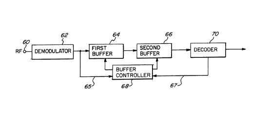
Figure 4 is a block diagram illustrating
decoder apparatus in accordance with the present
. invention: and
Figure 5 is a diagrammatic illustration showing
how the double buffer scheme of the present
invention is used to prevent errors in the received
data for a data block from corrupting the decoding
of subsequent data blocks.
Image
~10232'~
the variable length decoding unit is generally
constant.
Although the prior art structure of Figure 1
performs well in the absence of errors in the
received data, errors will normally occur. For
example, channel noise and nonlinearity of the
transmission channel can create errors in a received
data stream. When error corrupted codewords are
decoded by the variable length decoder 16, the
decoded results are likely to be different from the
original data that the codewords are intended to
represent. If there are errors in a coded data
block, it is unlikely that the total number of bits
generated by decoder 16 will equal the number of
bits contained in the block at the encoder. As a
result, the next block at the decoder will not start
at the correct position.
The results of such a data error are
illustrated in Figures 2 and 3. In Figure 2, an
original data word 20 comprises coded data 22 having
the three bit pattern 1 0 0. If an error occurs in
the second zero (designated by reference numeral
28), the received data 24 will comprise the
erroneous data bit indicated by reference numeral ..
30. Thus, the decoded word 26 will not be the same
as the original data word 20 that was intended to be
sent. This will usually result in a decoded word
that has a different length than the original data
transmitted for that word. This is illustrated in
210232
Figure 2, wherein decoded word 26 contains five bits
whereas the original data 20 only contained three
bits. Thus, although the only difference between
the coded data and received data illustrated in
Figure 2 is the error between bits 28 and 30, the
decoded words 26, 42, 46 are entirely different than
the original words 20, 32, 36.
Where a plurality of variable length codewords
are transmitted in block form, the error illustrated
in Figure 2 will affect the overall length of a '
decoded block. This is illustrated in Figure 3,
where block 0 (reference number 50) is supposed to
end at data boundary 54. However, since the total
number of bits in the decoded block is less than the
'15 actual number of bits for that block, the decoded
boundary will incorrectly be at the point
illustrated by data pointer 56. As a result, block w.
1 (designated by reference numeral 52) will not
start at the correct position. From this point on,
there is no way to recover the correct position of
the data pointer 56. The only solution is to flush
out the whole FIFO 14 and reinitialize it. In the
case of a decoder for HDTV, this will take at least
one frame time. This can result in unacceptable
artifacts in the decoded video, and is a major
disadvantage of using a FIFO as illustrated in
Figure 1 as the input buffer in a variable length
decoder.
2~4p232'~
In order to overcome this disadvantage, the
present invention provides a new buffer architecture
for a variable length decoder. In particular, the
present invention provides a pair of buffers as
illustrated in Figure 4. As in the prior art, the
transmitted variable length codewords input to
terminal 60~from an RF carrier signal are
demodulated in a demodulator 62. However, unlike
the prior art, the codewords are then input to a
first buffer 64 for subsequent loading into a second
buffer 66 under the direction of a buffer controller
68. The variable length codewords are output from
second buffer 66 to a conventional decoder 70.
First buffer 64 and second buffer 66 can comprise
FIFOs. First buffer 64 functions in the same way as
the FIFO 14 illustrated in Figure 1. However, it is
not reset during normal operation, even if there are
errors in the received data. All of the incoming
uncoded data is kept in first buffer 64.
Second buffer 66 is smaller than first buffer ,
64. Where processing is to occur on a block-by-
block basis, second buffer 66 only has to have a
storage capacity that is sufficient to store the
maximum size of a block. In a preferred embodiment,
the second buffer stores only one block of undecoded
data at a time, for decoding by decoder 70. Unlike
first buffer 64, second buffer 66 is reset by buffer
controller 68 at the beginning of the decoding .
process for each new block.
21023"r
When a new block is to be decoded, the
undecoded data for that block is read out from first
buffer 64 into second buffer 66 at a speed which is
equal to or higher than the decoding speed. This
5 transfer process is stopped when the data in the
first buffer 64 reaches the beginning of the next
block. This enables decoder 70 to complete the
decoding of the block stored in second buffer 66
during one decoder cycle.
10 At the commencement of the next decoder cycle,
the transfer cycle from first buffer 64 to second
buffer 66.is restarted, and the next data block is
written into second buffer 66 under the control of
buffer controller 68. Buffer controller 68 receives
15 the undecoded data via line 65, and determines from
this data the boundaries between each successive
data block. For example, the incoming data can
contain information as to the starting position of
each successive data block, which defines the data
block boundaries. Based on this information, buffer
controller 68 can enable first buffer 64 to transfer
data to second buffer 66 at the commencement of each
new data block, and to terminate the transfer at the
end of the.data block until the next decoding cycle
starts. The commencement of each decoding cycle is
communicated to buffer controller 68 from decoder 70
via line 67,
In a preferred embodiment of the present . '
invention, the data is packed into blocks. When the
~s~o2~~~
system is in normal operation, it is synchronized,
such that the.receiver has the knowledge of the
start point and end point of every received block.
All of the blocks are numbered. In an HDTV
embodiment, the blocks can be labeled, for example,
from 0 to 59 for each video frame. The block number
is provided at the beginning of each block of
incoming data.
When the decoder is first turned on, or if
disruption of data occurs in the transmission
channel, the data in the first buffer 64 will be
meaningless, and the buffer will have to be
resynchronized. The resynchronizing process (i.e.,
FIFO initialization) is commenced by resetting first
buffer 64 to insure that there is no data left
therein. The system then waits for a known signal,
such as a beginning of frame signal in an HDTV
implementation. Upon receipt of the known signal,
writing of the received data into first buffer 64 is
commenced. Thus, for example, the first block of a
given frame of video data will be written into first
buffer 64, followed by the second block of that
frame, etc. While this is occurring, the decoding
process is disabled.
Since the data in first buffer 64 is not read
out during the initialization process, the data at
the beginning of the first buffer will comprise the
first data block. When the time comes to decode the
first block of the current video frame, data is read
210232"
17
out from first buffer 64 and written into second
buffer 66 under the control of buffer controller 68.
The transfer cycle stops when the data read out of
first buffer 64 reaches the end of the first block.
Decoder 70 then decodes the first block of data from
second buffer 66. At the commencement of the next
decoding cycle, the transfer of the next data block
from first buffer 64 to second buffer 66 will
resume, and the second block will be decoded. As
indicated above, in order to ensure that-the second
buffer does not underflow, the transfer rate from
the first buffer must be equal to or greater than
the decoding rate.
The decoding process starts after the first
byte, or first few bytes of data of a given block
have been written into second buffer 66. Decoder 70
will continuously decode at a predetermined rate.
The decoding operation for each block will stop at
the end of that block. Decoding resumes at the same
rate for the next block during the next decoding
cycle.
In the structure according to the present
invention, the operation of reading data from first
buffer 64 is independent of the variable length
decoding provided by decoder 70. Thus, any error in
the data stream which affects the decoding process.
will not affect the synchronization of first buffer
64. At the beginning of each new block, the
undecoded data that is to be read out of first
2~oz~~~
buffer 64 is always synchronized. There is no need
to reset first buffer 64 every time an error occurs,
as was necessary in the prior art structure of
Figure 1. Only the second buffer 66 is reset for
each decoding cycle, and corruption of first buffer
64 by decoding errors is completely avoided.
Figure 5 illustrates the operation of the first
and second buffers during successive decoding
cycles. The first buffer receives data at an input
l0 end 80 and accumulates a plurality of successive
data blocks on a first-in first-out basis. At time
To, the first data block 72 is ready to be output
from the first buffer. The second buffer has been
reset and contains no data. As noted above, second
buffer 66 needs only to have sufficient storage
capacity for the maximum block size.
At time T~, the first data block 72 has been
transferred to the second buffer. The transfer is
stopped at the block boundary between first block 72
and second block 74. The second block is ready to
be transferred to the second buffer upon the
completion of the decoding of first block 72. After
the first block has been decoded, the second buffer
is reset, and at time TZ the second block 74 has
been loaded into the second buffer. Since the
second block is larger than the first block, it
occupies more space in the second buffer. However,
as long as the second buffer is large enough to,
210232'7
19
accommodate the maximum block size, it will not
overflow.
After the second block has been decoded, the
second buffer is again reset and at time TN, the nth
block 76 will be loaded into the second buffer. The
process continues in this manner indefinitely.
As can be seen from Figure 5, even if the data
in a particular block has been corrupted, the
decoding of only that one block will be affected.
Each remaining block is safely held in the first
buffer, with the block boundaries having been
properly.identified by buffer controller 68. In the
event that a data error results in the incorrect
determination of a block boundary, all subsequent
blocks will remain intact. In the event that a
block boundary error causes the second buffer to
overflow during one decoding cycle, subsequent
decoding cycles will not be affected.
It should now be appreciated that the present
invention provides an improved error protection
scheme for use in a variable length decoder. Two
separate buffers are provided. A first buffer
receives and stores incoming data. A second buffer
receives successive subsets of the incoming data
during successive decoding cycles. Since the
transfer of data from the first buffer to the second
buffer is independent of the variable length
decoding, the synchronization of the first buffer is
21a232'~
not affected by errors in the data stream that
result in incorrect decoding.
Although the invention has been described in
connection with a specific embodiment thereof, those
5 skilled in the art will appreciate that numerous
adaptations and modifications may be made thereto
without departing from the spirit and scope of the
invention as set forth in the claims.