Note: Descriptions are shown in the official language in which they were submitted.
. W~92/20829 1 PCr/S~92/00331
~02~0~ :
MAGNETOSTRICTIVE POWDER COMPOSITE AND METHOD5 F0R THE
MANUFACTURE THEREOF.
~he invention relates partly to a magnetostrictive
powder composite according to the preamble to claim 1, and ~ : :
partly to a method for the manufacturing o~ the magneto~
strictive powder composite according to the preambie to
claims 16 and 17. The powder composite according to the
invention is preferably used as a magnetostrictive element in
sound projectors and vibration generators, transducers,
actuators and in various types of linear motors.
To clarify the difference between permanent magnets and
magnetostrictive powder composites, key properties and
areas of applications for ~oth materials are listed below: ~:
PERMANENT MAGNE~S:
Properties :~
1. Permanent magnets, usually compounds of rare earth
metals and transition metals (Fe, Ni, Co) like for
instance SmCoS and Nd2Fe14B, are passive devices used
for generating a magnetic field. : :
2. Permanent magnets can only generate static magnetic
fields.
3. Permanent magnets are magnetized initially and posses
high remanence and high coercive force. Unreasonably
high energy would be needed to change the magnetic
field, which makes it practically impossible to use
permanent magnets for purposes other than to generate
static magnetic fields.
4. Permanent maqnets do not need an electric current
flowing in a coil or a solenoid to generate and
màintain the magnetic ~ield.
Application areas
A. Permanent magnets are used for generation of large
static fields in situations where it is difficult to
provide electric power or where the availability of
electric power is limited, or where geometrical
constraints such as space restrictions generate their
use rather than electromagnets.
W0 92/20829 ~ . . . 2 . PCr/SE92/00331
~,
21025 0~ B. The main applications of permanent magnets are in
electric motors ( in which elec~ric energy is
converted into mechanical energy), generators (in
which mechanical energy is converted into electrical
energy), loudspeakers, control devices for electron
beams such as in TV sets, magnetic levitation systems,
and various forms of holding magnets such as door
catches. For example Nd2Fe14B magnets developed by
General Motors are used in the starter motors of
their cars and trucks.
MAGNETOS~RICTI~E POWDER CONPOSITE:
Properties
l. Magnetostrictive powder composite is an active device
consisting of rare earth metals (RE) and transition
metals (Fe, Ni, Co and Nn), (RE)xFe1x, which changes
its length extremely much when exposed to an external
magnet:ic field. In contrast to traditional magneto-
strict:ive materials, such as Fe and Ni which display
magnet:ostrictive change in length of 9 ~m/m and 40 ~m/m
respectively, a magnetostrictive powder composite ~ ;~
displays length changes of more than l000 ~Im/m and is
therefore called giant magnetostrictive material.
Beacause of this, the magnetostrictive powder composite
is used to generate large and fast movements of high
precision and large force. In most applications this
large force is used to increase change in length and to
generate larger movements.
2. Nagnetostrictive powder composlte is usually used in
high frequency applications (up to 60 kHz), e.g.
for ultrasonics. In this~appllcation the purpose ~-
of the magnetostrictive composite is that it should -
work as an acoustic projector i.e. to generate fast
mechanical movements and ultrasound.
.
3. Magnetostrictive~powder composite is initially a
materlal with low ferromagnetism. Magnetic moments
within the magnetic domains in the material are randomly
oriented i.e. the material is not magnetized as in
the case of the above mentioned permanent magnets.
~W092/20829 3 21025 0 ~ PCT/SE92/00331
,.~
For a powder composite to pr~duce a length change one
has to apply mechanical stress on the material to
rotate magnetic domains relative the direction of the
applied stress, as well as to apply a high magnetic
field by ~eeding current into a coil surrounding the
material. Typical magn~tic fiel~s are 1 - 8 kOe.
4. The material constituting the magnetostrictive powder
composite has low remanence and low coercive force.
Chemical composition of the powder is chosen so that
the anisotropic energy is minimized. If one omitted
to do so it would be very difficult to use the
material in practice.
5. Magnetic powder composite has been put forward with a
purpose to increase the bandwidth o~ the casted giant
magnetostrictive material available on the market.
Magnetostrictive powder composite can manage a frequency
xegion of O - 60 kHz, while casted giant magneto-
strictive material only can manage O - 2 kHz. Giant
magnetostrictive alloys made of terbium, dysprosium and
iron are usually called Terfenol-D.
ApplicatiQn areas
Giant magnetostrictive powder composite is used in:
A.
- acoustic underwater sound projectors for high
frequencies,
- acoustic pro]ectors for ultrasound applications
~20 - 60 kHz),
- vibration generators (O - 60 kHz),
- positioners tto generate fast~ high precision motion),
and
B.
- wide bandwidth sound projectors and vibrators in which
the~amplitude does not change with frequency or load,
which is the case with conventional electromagnets.
Magnetostrictive powder composite according to the
invention presented has not been known of before. For
example the patent documents US, A, 4865 660, DK, B, 157
222, FR, A, 2065 359 and EP, A1, 175 535 do certainly refer
W092/20829 ; 4 PCT/SE92/0~331
21~2~0~
~ to magnetic powder composite materials, which nevertheless
all are permanet magnets and which find their applications
because of their capability to maintain permanent
magnetization. Magnetostrictive properties are not
S mentioned in the above referred documents. The fact that
the materials mentioned in these documents include powder
grains of rare earth metals and transition metals is of no
importance in this context.
When using conventional magnetostrictive materials and
in particular alloys of type (R~)XTl.x, where RE represents
one or a mixture of several rare earth metals, T represents
Fe, Ni, Co or Mn or a mixture of two or more of these
metals and x assuming a value 0 ~ x ~ 1 represents atomic
fraction, below mentioned rods, the following inconven-
iences will be manifested:
1. The magnetostrictive materials are manufactured in the
form of rods by casting. The casted rods hereby get
brittle characteristics and are beacuse of this very
difficult to machine with conventional techniques. ~ ;
~. Scrap from crashed rods is difficult to reuse.
3. The rods are brittle and can only withstand very small
tensional stress.
4. Due to a relatively low resistivity of casted
magnetostrictive rods, like for instance Terfenol-D
2S rods, in order to increase the frequency performance of
the said rods, it is often neccessary to slice the rods
and to glue them together again in order to decrease the
electrically conductive cross section of the material
~ and to thereby decrease eddy current losses.
5. Due to the low permeablity of a conventional casted
magnetostrictive rod it is difficult to magneti e
homog~neously such a rod by the use of permanent magnets
- applied at its ends. Usually a fairly homogeneous
~ magnetic flux can only be achieved if the rod length is
not larger than 3 times its diameter.
6. The low permeability of the casted rod also causes
magnetization at the rod ends to be lower compared to
-
W092/20829 5 210 2 ~ ~ ~ PCT/SE92/00331
,_,
the rod centre when a conventional coil is used to
magnetize the rod.
7. So far it has only been possible to produce magneto-
strictive elemen~s in form of rods with circular ~ross
sections. This causes a large material wastage and a
costly machining if another geometrical form is
required.
By either crushing the scrapped magnetostrictive rods in
an oxygen free atmosphere, or crushing magnetostrictive
ingots or directly atomizing magnetostrictive powder or by
hydrogen decrepitation producing a magnetostrictive powder,
and thereafter pressing the crushed scrap or powder
together with a binder, all of the above accounted
inconveniences can be decreased or eliminated. To maximize
the magnetostriction one can magnetically align the
material before it is pressed isostatically and the binder
has been cured. This is accomplished by applying a
magnetizing field along the working direction of the
magnetostrictive powder composite.
The above mentioned disadvantages 1 - 6 with the
existing technique are matched by the following advantages
if the invention is utilized:
1. The powder composite is so tough that it can be shaped
with a conventional cutting technique.
2. Scrap from crushed rods can be ground in an oxygen free
atmosphere and thereafter reused for new rods.
3. If for example reinforcement fibres, preferably of
aluminium oxide, silicon carbide, Kevlar, carbon, glass
~-~ or titanium, are pressed into the rod and aligned longi-
~- tudinalIy or-perpendicularly, tensile strength and -
elastic modulus will be increased~
4. By coating the grain surface with an electrically
insulating material or by using a binder that insulates
the grains from each other, eddy current losses can be
decreased. The invention utilizes such binding agents
which wet said grains and bind them together and
possibly also form an electrically conducting layer
between the powder grains or between the grain ;
: .
"X~D~
W092/20829 6 PcT/SE92/0o33l
2 1 Q 2 5 ~ } ! ~)
agglomerates. These requirements are fulfilled e.g. by a
number oX known resins and thermoplastics. Ceramics and
oxides, preferably rare earth oxides because of a high
reactivity of Terfenol-D, can also be used as an
insulating coating. -
5. A homogeneous magnetic field generated by pe~manent ;~
magnets can be achieved if a powder of a permanent
magnet type, preferably Nd2Fe14B, is mixed with the
magnetostrictive powder, preferably along the rod axis,
in order to decrease the leakage flux. This will make it
possible to manufacture rods with length/diameter ratios
larger than 3:1.
6. To avoid lowering of magnetization at the rod ends high
permeability and high resistivity powder grains,
preferably of coated iron, nickel, cobalt or amorphous
iron, like for instance metglas, or alloys of these, can
be pressed into the rod ends.
7. Magnetostrictive powder composite can be directly
pressed to a final shape, whereby expensive material
wastage is avoided.
In addition, the invention provides for the following ; ;
advantages:
- The surface friction of the magnetostrictive powder
composite can be lowered, so that it can glide easier
against other objects. Also, its chemical resistance can
be increased by coating the magnetostrictive powder
composite, after it has been pressed, with a thin layer
of non-organic material, such as aluminium oxide or an
.
~ organic material, such as teflon, or if during pressing
~the composite-surface is provided with a powder coating
made of the above mentioned organic or non-organic
materials. -
The strength of the magnetic powder composite can be
~ increased by coating its surfaces, which are in contact
with other objects and thereby are exposed to a ~ ~-
mechanical load, with a layer made of e.g. aluminium
oxide or silicon carbide.
,~"'.-" ~
W092/20829 7 PCT/SE92/00331
210'~50~
- In addition, by tha use of powder technology, additional
coil loops and/or coolant chann~ls can be integrated
into the pressed form. ~ ~ ~
Different embodiments of the invention are shown ~;
in the enclosed figures.
Fig 1 shows a magnetostrictive composite rod 1 which,
besides the magnetostrictive powder, possible coating and ~-
a binder, also has permanent magnets 2 of a conventional ~
type at the rod ends and aligned permanent magnet powder 3, -
mainly along the longitudinal axis of rod 1, which makes
the working magnetization in the composite rod 1 more
homogeneous.
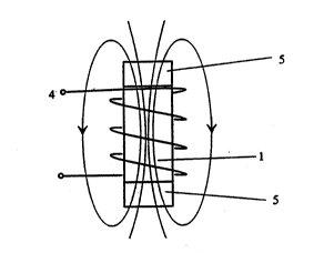
Fig 2 shows a magnetostrictive composite rod 1, an
excitation coil for generating magnetizing field 4 and iron
powder, coated with a thin electrically insulating Iayer of
Fe2O3 or equivalent material, which has been pressed into
the ends 5 of the rod l. With this design a homogeneous
magnetic flux in the composite rod 1 is achieved.
Fig 3 shows a magnetostrictive composite rod 1 with
longitudinal fibre reinforcement 6 which, besides
reinforcing the rod 1 and increasing its strength against
tensile stress, also makes it possible to build in a
prestress into the rod 1.
The magnetostrictive composite material according to
the invention must exhibit low anisotropic energy and high
magnetostriction in order to find practical use. It is
therefore important to minimize the anisotropic energy and
at~the same time to optimize the room temperature magneto-
striction of the composite material. A number of composite
materials~with chemical composition (RE)XT1X, where RE
represents one or a mixture of several rare earth metals, ~ ~-
T represents Fe,-Ni, Co or Mn or a mixture of two or more
of these metals and x assuming a value 0 < x ~ 1 represents
atomic fraction, will have the mentioned properties. At
evaluating different compositions of magnetostrictive
composite rods 1 according to the invention the applicant
has found that the following compositions A) - F) give good
such properties in the composite rods~
: ;,,
;~". ~ '.',".'
~-iW092/20829 2 1 ~ 2 5 Q 1 8 PCT~SE92/00331
A) Tb
wherein x and w represent atomic fractions within
0.2 ~ x ~ 1.0 and o ~ w ~ 0.5.
B) TbxHo1-xFe2-
~
wherein x and w represent atomic fractions within
0.1 ~ x ~ l.o and o ~ w ~ 0.2. .
C) SmxDy1-xFe2
wherein x and w represent atomic fractions within
0.8 ~ x ~ 1..0 and 0 S w ~ 0~2.
D) SmxHo~-xFe2~
wherein x and w represent atomic fractions within
0.6.~ x ~ 1.0 and 0 ~ w ~ 0.2.
E) TbXHoy~yzFe2-~
whereîn x, y, z and w represent atomic fractions within
0.1 ~ x ~ 1.0,
O ~ y ~ o.s, , . ... ,:~
0 ~ z ~ 0.8,
and 0 ~ w ~ 0.2 :~
and x ~ y + z = 1.
F) SmxHo~)yzFe2-
~wherein x, y, z, and w represent atomic fractions within
0.6 ~ x S 1.0,
0 ~ ~ ~ 0.4,
0 ~ z ~ 0.4,
and 0 ~ w ~ 0.2
and x + y ~ z = 1.
Although some particularly favourable compositions of
;magnetostrictive composite materials are accounted for in ~-
the above~ it is understood that even other compositions
with:good properties are contained within the scope of the
invention.
In order to improve the magnetostrictive composite
. .-material-described by the invention, to increase the ~ :
derivative d~/~H, where ~ is magnetostriction and H is the .
magnetizing field, as well as magnetostriction at
saturation one can, after pressing and after the binder has
been cured, expose the magnetostrictive composite material
to the following heat treatment~
~ ~'
W092/20829 ~ PCT/SE92/00331
2 ~ 0 ~
- composite material is heated to a temperature .
above its Curie temperature, which means about 400C,
- thareafter, a magnetizing field of 40 kA/m amplitude : -~
is applied, .
- finally the composite material is cooled down, ;~
with the magnetizing field still being applied, to.a
temperature below its Curie temperature.
The composite material can be further improved if it is
expo~ed to external vibrations during pressing. This will
increase the density and the psrmeability as well as
facilitate the magnetic alignement of the magnetostrictive ..
grains.
The above described method of manufacture of the
magnetostrictive powder composite according to the
invention often demands high pressing forces. In an
alternative mode of execution according to the invention
isostatic pressing is used, which usually means a lower
pressing force than in the above described method.
In said alternative method, the magnetostrictive
powder grains and the ~inder are pressed together
isostatically, at which the composite material is directly
pressed to an arbitrary final shape.
This isostatic pressing can be improved by magnetically
aligning the magnetostrictive grains before the composite
material has been pressed and before the binder has been
cured. This is achieved by applying the magnetizing field
along the working direction of the magnetostrictive ~ :
powder composite.
. ~
'' ~ ' ^' '.' '' - ., ;'.,';
.~ ~