Note: Descriptions are shown in the official language in which they were submitted.
AE-384 PATENT
2102563
ELECTRICAL CONNECTOR COMPONENT HAVING SECURED SEAL
1 FIELD OF THE INVENTION
This invention relates generally to electrical connectors
and pertains particularly to apparatus and methods for providing
sealing of electrical connectors against ambient environment.
BACKGROUND OF THE INVENTION
So-called "I/O Headers", i.e., input/output headers, are a
typical component of electrical connectors, constituted of a
body of electrically insulative material, generally rectangular
in outline, with upstanding end walls and sidewalls extending
between the end walls, the walls collectively defining
therewithin a compartment for receipt of a mating plug, and a
base or floor at the interior of the compartment and supporting
electrical contact members, e.g., contact pins upstanding from
the base to enter female contacts of the mating plug on
insertion of the mating plug into the header. While what has
been described is a male header, the industry also encompasses
female headers, wherein the contacts of the mating plug are
adapted for the receipt of contact pins extending outwardly of
the mating plug.
Headers, themselves, are resident in such as a PCB (printed
circuit board) or other support housing.
*
2102563
1 In various applications, it is imperative to provide sealing
at respective mating surfaces, i.e., in the described header -
mating plug - PCB instance, as between the header and the mating
plug and as between the header and the PCB. Known headers do
not themselves incorporate sealing facility. Sealing members
are thus provided, separately from the header, to effect the
requisite sealing as against ambient environment, e.g., ingress
of moisture therefrom into the header.
Disadvantage attends the known practices in that sealing
components need be inventoried separately from the headers,
mating plugs and PCBs and in that connection assembly is
labor-intensive in requiring steps of effecting sealing apart
from simple mating of headers, mating plugs and PCBs. Further,
sealing components which are provided separately from headers
are subject to damage in handling and then suffer in
effectiveness upon assembly with headers.
SUMMARY OF THE INVENTION
The present object has as its primary object the provision
of improved electrical connector components.
A more particular object of the invention is to provide
electrical connector components having seals therewith.
A specific object of the invention is to provide improved
headers for sealed engagement with mating plugs through the use
of seals combined fixedly with the headers.
2 1 02563
A more specific object of the invention is to
provide improved headers for sealed engagement with both
mating plugs and PCBs through the use of seals combined
fixedly with the headers.
In attaining the foregoing and other objects, the
invention provides an electrical connector component
comprising a body member defining a compartment therein
having an open end for the receipt of a mating electrical
connector component, the body member defining an interior
recess adjacent the open end thereof, the body member
further defining a mating surface located oppositely with
respect to the open end and defining an exterior recess
adjacent the mating surface, a sealant material disposed
in first part continuously interiorly of the body member
in the interior recess, in second part continuously
exteriorly of the body member in the exterior recess, and
in third part interiorly of the body member continuously
with the sealant material first and second parts, the
body member defining a key structure for polarized
receipt of the mating electrical connector component, the
sealant material third part being resident at least in
part interiorly of the key structure.
Furthermore, the present invention provides a sealed
header comprising: an insulative body member including a
base, a pair of spaced sidewalls and a pair of spaced
endwalls upstanding from the base, the spaced sidewalls
and endwalls defining a compartment having an open end
within the body member; a plurality of electrically
conductive contact pins supported by the base, a portion
VLS:in 3
2 1 02563
_ of the pins extending within the compartment for mating
engagement with complemental contacts of a mating
connector and a portion of the pins projecting outwardly
for connection to an electrical component; an interior
seal disposed continuously on interior surfaces of the
sidewalls and endwalls adjacent the compartment open end
and spaced from the contact pins, the interior seal
adapted to provide sealed receipt of the mating
connector; and an exterior seal disposed on an exterior
surface of the body member adjacent the base and
continuously around the periphery thereof, the exterior
seal being spaced from the pins and adapted to provide
sealed communication with the electrical component.
The foregoing and other objects and features of the
invention will be further understood from the following
detailed description of preferred embodiments thereof and
from the drawings, wherein like reference numerals
identify like components throughout.
DESCRIPTION OF THE DR~WINGS
Fig. 1 is a front side elevation of a header in
accordance with the invention.
Fig. 2 is a top plan view of Fig. 1 header.
Fig. 3 is a right side elevation of the Fig. 1
header.
Fig. 4 is a bottom plan view of the Fig. 1 header.
VLS:in 4
2102563
1 Fig. 5 is a sectional view of a body member of the Fig. 1
header as would be seen from plane V-V of Fig. 1, prior to
introduction of sealant therein.
Fig.6 is a partial top plan view of the Fig. 5 header body
member.
Fig. 7 is an enlarged repeat showing of Fig. 5, with sealant
resident therein and shown in section, with sectioning for the
body member omitted to enhance illustration of the sealant.
Fig. 8 is a partial sectional view of the header body member
with sealant resident therein as would be seen from plane
VIII-VIII of Fig. 7.
DETAILED DESCRIPTION OF PREFERRED EMBODIMENTS AND PRACTICES
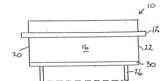
Referring to Figs. 1-4, header 10, typically a molded
plastic unit, includes a body member having a mounting flange 12
and defining an open compartment 14, bounded by sidewalls 16 and
18 and end walls 20 and 22. A seal 24 is secured to upper
regions of walls 16-22 and extends continuously around
compartment 14 for purposes of effecting sealed receipt of a
mating connector component (not shown).
Contact pins 26 are supported in header base or floor 28,
extending therebelow for mating engagement with a PCB or the
like (not shown) and extending upwardly of the base for mating
engagement with complemental contacts of the mating connector.
2102563
1 A seal 30 is secured to header 10 at its underside and
extends continuously around the header for purposes of effecting
sealed communication in the connection of the header to the PCB.
Figs. 5 and 6 depict the header body member with contacts 26
omitted and seals 24 and 30 not yet secured therewith. An upper
cutout portion forming recess 31 leads to ledge 32. A
polarization key 34 is formed on the interior of sidewall 18 and
includes wings 34a and 34b and channel 34c formed between the
wings and in flow communication with recess 31. A further
channel 36 also communicates with recess 31 and extends
interiorly of sidewall 16. Each of walls 16-20 is undercut to
form recess 38, which extends continuously around base 28.
Each of channels 34c and 36 is further in flow communication
with recess 38. Contact pin passages 40 complete description of
the header body member.
Referring to Figs. 7 and 8, seals 24 and 30 will be seen to
be both constituted by a common sealant, preferably silicone.
In reaching the header with seals thus introduced, the header
body member is placed in an exterior mold die conforming to the
illustrated (sealant-inclusive) exterior of Figs. 7 and 8. An
interior mold die in introduced into compartment 14 and has a
configuration adapted to form the sealant in conformity with the
illustrated (sealant-inclusive) interior of Figs. 7 and 8.
Showings of the mold dies are not included since their structure
will be appreciated as complemental to the showing of Figs. 7
and 8.
--6--
2102563
-
l A sealant input port is provided adjacent the upper portion
of the interior mold die and an air escape vent is provided in
the exterior mold die. The introduced sealant flows throughout
recess 31, through channels 34c and 36 and throughout recess 38,
thus providing the seal configuration of Figs. 7 and 8.
In further explanation of the invention in its method aspect
and by way of introduction to the ensuing claims, the invention
will be seen to provide a method for providing sealing as
between a first electrical connector component, e.g., a header,
and a second electrical connector component, e.g., a mating
pluq, involving the steps of configuring the first electrical
connector component as a body member defining a compartment
therein having an open end for the receipt of the second
electrical connector component and a recess extending from the
lS open end interiorly of the compartment and about the interior
periphery of the body member and securing sealant material in
the recess. The recess is desirably configured to extend
continuously about the interior periphery of the body member.
In reaching the particular type of component discussed
above, the applicable steps are configuring the first electrical
connector component as a body member defining a compartment
therein having an open end for the receipt of the second
electrical connector component and having a substantially closed
end opposite the open end, a first recess extending from the
--7--
2102563
1 open end interiorly of the compartment and about the interior
periphery of the body member and a second recess extending about
the periphery of the body member opposite end and open
exteriorly of the body member and securing sealant material in
each of the first and second recesses.
The first recess is configured to extend continuously about
the interior periphery of the body member and wherein the second
recess is configured to extend continously about the periphery
of the body member opposite end. The body member is further
configured to have a channel extending from the first recess to
the second recess and opening into each of the first and second
recesses. The body member is also configured to have a
polarization member and one of the channels is formed in the
polarization member.
While the channels 34c and 36 are shown in Figs. 5 and 6 as
being disposed along the same section of the body member, they
may of course be disposed in mutually different sections of the
body member.
In its apparatus aspect, the invention will be seen to
provide an electrical connector component comprising a body
member defining a compartment therein having an open end for the
receipt of a mating electrical connector component, the body
member further defining a recess adjacent the open end thereof,
and sealing means for sealing engagement with the mating
2102563
-
1 electrical connector component, the sealing means being fixedly
secured to the body member and resident in the recess. The
component may further define a mating surface located oppositely
with respect to the open end and a further recess adjacent the
mating surface, the sealing means being resident also in the
further recess.
The sealing means may comprise a sealant material disposed
in first part continuously interiorly of the body member
adjacent the open end thereof and in second part continuously
exteriorly of the body member adjacent the mating surface.
Further, the sealant material may be disposed in third part
interiorly of the body member contiguously with the sealant
material first and second parts. The body member desirably
defines a key structure for polarized receipt of the mating
electrical connector component and the sealant material third
part is resident at least in part interiorly of the key
structure. The body member includes a plurality of walls
bounding its compartment, at least one of the walls providing a
channel also for residence of the sealant material third part.
Various changes in structure to the described connector
component and practices for effecting connection of electrical
components may evidently be introduced without departing from
the invention. By way of example, the invention may be
practiced with both ends of the connector component defining
2102563
1 compartments for receipt of mating plugs, in which case
compartment 14 and seal 24 are formed at each end of the
connector component, with channels for sealant flow
interconnecting recesses 31 formed interiorly of the both ends.
Likewise, the invention contemplates the provision of recesses
38 and seals 30 at both ends of a single connector component
with channels for sealant flow interconnecting the recesses 38.
The invention further contemplates the molding of further seals
on the upper and lower surfaces of mounting flange 12 whereby it
also may be in sealed relation with companion apparatus mounting
surface. As noted, while the depicted embodiment employs male
contact pins, connector components in accordance with the
invention may employ female contact members. Accordingly, it is
to be understood that the particularly disclosed and depicted
embodiment is intended in an illustrative and not in a limiting
sense. The true spirit and scope of the invention are set forth
in the following claims.
--10--