Note: Descriptions are shown in the official language in which they were submitted.
'~'~93/19929 2 ~ O ~J 6 ~ ~ PCT/EP93/~745
-- 1 --
TIRE UNIFORMITY CORRECTION WITHOUT GRINDING
The present invention relates generally to a pneumatic
vehicle tire, and to a method and anapparatus for correcting
at least one uniformity characteristic in the tire. In
particular, the present invention relates to correcting the
uniformity characteristic in the tire, such as radial force
variation and/or conicity, without grinding any part of the
tire.
It is known in the tire industry that it is difficult to
manufacture a toroidal shaped pneumatic radial tire
consistently the same every time from sheet and/or strip
material. A typical pneumatic radial tire includes a pair of
axially spaced apart and circumferentially inextensible
beads. A carcass ply extends between the beads and is
attached to a respective bead at axially opposite end
portions of the carcass ply. The carcass ply includes a
plurality of parallel extending reinforcing members. The
carcass ply is formed into a toroidal shape and has a belt
package located radially outward of the carcass ply in a
crown portion of the tire. Tread rubber and sidewall rubber
are applied over the belt package and carcass ply,
respectively.
After the tire is assembled and cured, the tire is typically
tested for a uniformity characteristic. "Uniformity" is
defined herein as what a "perfect" or "ideal" tire would
yield for certain measured characteristics when tested during
rotation. "Uniformity characteristic" is defined herein as a
deviation in those certain characteristics from what the
perfect tire would yield during the testing.
Testing a tire for a uniformity characteristic typically
begins with mounting the tire in an inflated condition on a
W093/19929 PCT/EP93/~7~'
2102G18 2 -
test spindle of a uniformity tester. A test wheel is moved
into engagement with the tire to radially deflect a portion
of the tire a predetermined amount. The position of the axis
of rotation of the test wheel relative to the axis of
rotation of the tire is then fixed by a locking mechanism.
The test wheel is rotated to cause rotation of the tire.
Sensors associated with the test wheel sense radial and
lateral loads transmitted by the tire to the test wheel
during rotation of the tire.
One uniformity characteristic test which is generally
performed on the tire is a test for radial force variation.
Radial force variation is typically expressed as a variation
in the force against the test wheel which is sensed during
rotation of the tire. Radial force variation can be
represented by a combination of a first harmonic radial force
variation through an Nth harmonic radial force variation or a
composite radial force variation. The Nth harmonic~is the
last harmonic in a Fourier Series analysis of the composite
radial force variation which is deemed acceptable to
accurately define the radial force variation. It is known in
the tire and automobile industries that vehicle ride is
generally most affected by the first harmonic radial force
variation of the tire.:The first harmonic radial
force variation is often associated with "radial runout" of
the tire. Radial runout is defined as a difference in the
radius from the axis of rotation to the outer periphery of
the tire tread around the tire.
Another uniformity characteristic test which may be performed
on the tire is a test for conicity. Conicity is defined as
the tendency of a rotating tire to generate a lateral force
regardless of the direction of rotation of the tire. Conicity
is expressed in terms of average lateral force generated
during rotation in both directions of the tire against the
~93/19g2g 21~ ~J ~13 PCT/EP93/00745
-- 3
load.
Such uniformity characteristics may be attributed to the
manufacture of a tire from the sheet and/or strip material.
The uniformity characteristics can simplistically be viewed
as a deviation from perfect roundness of the outer
circumference of the tire, as deviation from spindle load
transmitted by a perfect tire during rotation (radial force
variation) or as deviation from straight tracking during
rotation (conicity). For example, the tread rubber of the
tire may be thicker or thinner in one location around the
outer circumference of the tire. There may also be areas of
the tire having increased strength because of a doubling of a
tire reinforcement, such as at the splice from sheet carcass
ply material. Lack of bead concentricity of the tire may also
be a problem. The beads of the tire may be not exactly
concentric relative to the axis of rotation of the tire or
the tread may not be concentric with the beads (radial
runout). The carcass ply of the tire may be subjected to more
or less localized stretch of the carcass reinforcing members
during assembly of the tire. The molding and curing processes
of the tire assembly could also create localized stretching
of the carcass reinforcing members. The belt package of the
tire may be axially displaced or conically shaped.
If the uniformity characteristic of the tire has a magnitude
which is less than a predetermined relatively low minimum
magnitude, which is deemed not to be detrimental to a vehicle
ride or produce undesirable vibrations in the vehicle, the
tire may be shipped to a customer. If the uniformity
characteristic magnitude is greater than a predetermined
maximum threshold magnitude, the tire is scrapped. If the
uniformity characteristic magnitude is between the relatively
low minimum magnitude and the maximum threshold magnitude,
the tire may be suitable for correction.
WO93/1~29
_ 4 _ PCT/EP93/~7
2 i ~2~1~
Typically, prior art correction of a uniformity
characteristic of a tire, such as radial force variation,
included grinding of tread rubber about the outer
circumference of the tire at a selected location and up to
180 degrees about the outer circumference of the tire.
However, grinding of the tire has certain disadvantages. For
example, grinding can contaminate a tire plant environment,
reduce the useful tread life of the tire or may render the
tire visually unappealing. Prior attempts at correcting a
pneumatic tire uniformity characteristic without grinding are
disclosed in U.S. Patents Nos. 3,529,048 ; 3,632,701 ;
3,838,142 ; 3,872,208 ; 3,880,556 ; 3,945,277 and 5,060,510.
U.S. Patent No. 3,529,048 discloses placing a tire on a
fixture immediately after the tire is removed from a mold and
before it is cooled. The tire is inflated to its recommended
operating pressure. A radial load is applied to the tire and
the 'ire is rotated for a time at least equal to the tire
cure time. The flexing of portions of the tire allow
components or portions of the components of the tire to
"relatively move" before the tire is completely cured to
yield uniform stresses in the components.
U.S. Patent No. 3,632,701 discloses heating a tire after
curing to a temperature elevated above an ambient
temperature. The elevated temperature is maintained for about
sixty minutes while the tire is inflated to a pressure of up
to S0 psi. This obviously has drawbacks in a modern tire
production plant because of the relatively long time required
to correct the uniformity characteristic of the tire compared
to a cure cycle time of less than thirty minutes for a
passenger car radial tire.
- 5 -
U.S. Patent No. 3,838,142 discloses subjecting selected
sections of the tire to radiation to increase the modules of
elasticity of those sections. U.S. Patents 3,872,208 and
3,880,556 disclose applying heat to a portion of the inner
surface of the tire. U.S. Patent No. 3,945,277 discloses
applying heat to the tire sidewalls during rotation of the
tire in contact with rollers in order to "condition" the tire.
U.S. Patent No. 5,060,510 discloses correcting radial force
variation of a tire and rim assembly without grinding the
tire tread. A pair of circumferential shims are placed
between respective tire bead areas and mounting areas of the
rim as a function of the measured radial force variation.
Each shim has a varying thickness over its circumference. For
a flat seat rim, the largest thickness portion of the shims
are placed at the location of the largest amplitude of the
radial force variation.
The present invention is directed to correcting a uniformity
characteristic, such as radial force variation or a conicity,
in a fully cured pneumatic tire and particularly in a radial
pneumatic tire. The method and apparatus of the present
invention accomplishes such correction without the drawbacks
of the prior art methods which can be energy inefficient,
costly and/or time consuming. The present invention is, thus,
directed to an apparatus and a method for correcting at least
one uniformity characteristic in the tire in a relatively
short period of time and without grinding. The
present invention is also directed to a tire resulting from
the uniformity characteristic correction by such method and
apparatus.
According to the present invention there is provided a method
for correcting a uniformity characteristic in a cured tire
containing carcass reinforcing members, the correction being
a function of indications of the magnitude and location of the
uniformity characteristic, said method comprising the steps
of causing permanent deformation of at least one portion of
at least one carcass reinforcing member at a location selected
in response to an indication of location of the uniformity
characteristic, and controlling the magnitude of the
deformation to said at least one portion of said at least one
carcass reinforcing member at the selected location in
response to an indication of the magnitude of the uniformity
characteristic.
Preferably, the method further includes the steps of:
- determining the angular locations and magnitude of a first
harmonic of a uniformity characteristic;
- determining the angular locations and magnitude of at
least one other harmonic of the uniformity characteristic;
and
- calculating a composite wave form as a function of said
first and said at least one other harmonic of the
uniformity characteristic, wherein said deformation
causing step comprises permanently deforming at least one
carcass reinforcing member at selected positions around
the sidewall of the tire by restraining portions of the
sidewall of the tire by predetermined amounts at
predetermined angular locations as a function of the
composite wave form.
According to the present invention, there is also provided an
apparatus for correcting a uniformity characteristic in a
cured tire containing carcass reinforcing members, the
correction being a function of indications of magnitude of
said uniformity characteristic comprising:
- means for causing permanent deformation of at least one
~ I )
A I
6a
portion of at least one carcass reinforcing member at a
location selected in response to an indication of location
of the uniformity characteristic; and
- means for controlling the magnitude of deformation by said
deformation causing means to said at least one portion of
at least one carcass reinforcing member at the selected
location in response to an indication of the magnitude of
the uniformity characteristic.
The apparatus may further include:
- a frame for receiving the tire in a mounted condition;
- reference means for determining the position of the tire
within the frame as a function of the location indications
on the tire;
- at least one restraining member which is movable relative
to the frame and comprises a contact member having a
surface for restraining a portion of the sidewall of the
tire;
- means for moving the member to engage the surface with the
sidewall of the tire; and
- means for inflating the tire to a predetermined inflation
pressure for a predetermined time in response to the
magnitude indication.
According to the present invention, there is also provided a
tire comprising:
- a pair of spaced apart and substantially circumferentially
inextensible beads;
- a carcass extending between said beads and having axially
opposite end portions attached to respective beads, said
carcass including a plurality of parallel extending
reinforcing members; and
- a belt package located radially outward of said carcass at
a crown portion of the tire, wherein at least one of said
carcass reinforcing members located in a sidewall of the
tire has a portion permanently deformed beyond its elastic
A
b ~ 6 ~ ~ .
limit to reduce a uniformity characteristic of the tire.
Correction of the tire is typically performed when the
magnitude of the uniformity characteristic is within a
predetermined range of magnitudes. The reducing step and/or
means preferably includes stretching at least a portion of the
carcass reinforcing member beyond its elastic limit for a
predetermined time. The stretching results in a permanent
lengthening of the carcass reinforcing member as a function
of the magnitude of the uniformity characteristic, but
preferably by at least 0.1 percent.
The magnitude of the uniformity characteristic varies
circumferentially around the tire as given by the signal.
Stretching the carcass reinforcing members for proper
correction must also vary circumferentially around the tire.
Variable stretching is associated with a means for providing
a variable tension in the carcass reinforcing members. This
can be achieved by a tension applied to each individual
carcass reinforcing member or by a method of restraining
AI
' 093/1~29 2 ~ d 2 ~ ~ ~ PCT/EP93/00745
reinforcing members over a side or predetermined angular
segment of the tire. The type and amount of restraint is a
function of the uniformity characteristic, the magnitude and
location of the correction, the pressure or force applied, as
well as the physical parameters of the tire.
Consider the signal to be indicative of a composite or total
radial force variation. Total radial force variation may be
analyzed to determine the first harmonic radial force
variation or a predetermined other harmonic. A portion of the
sidewall of the tire may be restrained a maximum amount at a
location 180~, for the first harmonic, circumferentially
spaced from the location indicated by the signal and a
minimum amount, or not at all, at the location indicated by
the signal. The sidewall may be linearly restrained to a
gradually lesser amount in both circumferential directions
from the location of maximum restraint toward the location of
minimum restraint. Alternatively, non-linear restraint may be
applied to the sidewall of the tire.
The minimum restraint permits a maximum amount of permanent
deformation to at least one carcass reinforcing member at the
location of minimum restraint. A gradually lesser amount of
permanent deformation may then be provided to other carcass
reinforcing members in both circumferential directions from
the location of minimum restraint to a minimum amount of
permanent deformation at the location of maximum restraint.
Restraining the sidewall or sidewalls of the tire can be
accomplished by an annular restraint device having a planar
side surface for engaging an annular portion of the sidewall.
The radial length of engagement of the restraint device may
be a relatively small percentage of the section height of the
tire. Alternatively, another restraint device may be provided
in which the radial length of engagement may be a relatively
2 ~
large percentage of the section height of the tire. The
orientation of the restraint device relative to the mid-
circumferential plane of the tire may be varied as a function
of the magnitude of the radial force variation.
Conicity of the tire may be corrected by permanently deforming
a portion of all carcass reinforcing members a substantially
equal amount in only one sidewall of a tire indicated by the
signal. Conicity may also be corrected by permanently
deforming a portion of the carcass reinforcing members at the
side of the tire indicated by the signal by an amount
different than a permanent deformation applied to a portion
of the carcass reinforcing members in the other side of the
tire.
According to the present invention there is also provided a
method for reducing the magnitude of a uniformity
characteristic in a cured tire, said method comprising the
steps of:
- generating a signal indicative of the magnitude of the
uniformity characteristic and the location on the tire to
be corrected; and
- permanently deforming as a function of the magnitude of
the uniformity characteristic at least a portion of at
least one carcass reinforcing member of the tire at the
location indicated by the signal.
According to the present invention, there is also provided an
apparatus for reducing the magnitude of a uniformity
characteristic in a cured tire generated by the tire during
a uniformity characteristic test, said apparatus comprising:
- means for generating a signal indicative of the magnitude
of a uniformity characteristic and the location on the
tire to be correctedi and
- means for permanently deforming as a function of the
magnitude of the uniformity characteristic at least a
portion of at least one carcass reinforcing member of-the
tire.
The carcass reinforcing members are preferably made from a
polyester material.
The permanently deformed portion of the carcass reinforcing
member is preferably located in a sidewall of the tire. The
portion of the carcass reinforcing member is permanently
elongated by at least 0.1 percent.
Further features of the present invention will become
apparent to those skilled in the art to which the present
invention relates from reading the following specification
with reference to the accompanying drawings, in which :
. Fig. 1 is a flow diagram of process operations for testing
and analyzing the uniformity characteristics of a tire ;
. Fig. 2 is a graphical representation of a composite radial
force variation of a tested tire as a function of the angular
location around the tire ;
. Fig. 3 is a graphical representation of the initial values
of the first through third harmonics of a radial force
variation of the tested tire ;
. Fig. 4 is a graphical representation of composite radial
force variations of a tire having a first harmonic corrected
according to the present invention, before and after running
of the tire ;
. Fig. 5 is a graphical representation of the first through
third harmonics of radial force variation after correction of
the first harmonic of the tire ;
. Fig. 6 is an elevational view of an apparatus embodying the
present invention for correcting a uniformity characteristic
of a tire ;
~, , i,
9a ~ 8
. Fig. 7 is a view of the apparatus in Fiq. 6 with parts
moved to different positions illustrating use of the method
and apparatus ;
. Fig. 8 is a cross-sectional view of a tire mounted in a
portlon of the apparatus embodying the p~ v~ a-
~
Al
~ 93/19929 PCI'/EP93/007~ -
21~6i~ - lo -
illustrating restraint of the sidewalls of the tire ;
. Fig. 9 is an enlarged cross-sectional view of a portion of
the tire and apparatus illustrated in Fig. 8 ;
. Fig. 10 is a schematic representation of a sidewall portion
of a carcass reinforcing member in Fig. 9, before and after
maximum restraint of the sidewall ;
. Fig. 11 is a cross-sectional view of a portion of a carcass
reinforcing member restrained at two radial locations
according to an alternate embodiment restraint ring of the
present invention ;
. Fig. 12 is a graphical representation of permanent
elongation of carcass reinforcing members between locations
of minimum and maximum restraint of the sidewall in both
directions and as a function of angular location around the
tire ;
. Fig. 13 is a side view of a tire before and after
correction illustrating the introduction of radial runout of
the tire to offset an existing radial force variation ;
. Fig. 14 is a flow diagram of the correction method
embodying the present invention ;
. Fig. 15 is a cross-sectional view of an alternative
embodiment restraint of the tire sidewall ;
. Fig. 16 is a schematic representation of a portion of a
carcass reinforcing member before and after restraining the
sidewall according to the embodiment illustrated in Fig. 15 ;
. Fig. 17 is a cross-sectional view of another alternate
embodiment illustrating stretching a sidewall portion of the
carcass reinforcing member by a mechanism ;
. Fig. 18 is a graphical representation of the carcass
reinforcing member stretched according to the embodiment
illustrated in Fig. 17 ;
'~093/19929 2 1 ~ 2 ~ ~ ~ PCT/EP93/~745
-- 11 --
. Fig. 19 is a graphical representation of yet another
alternate embodiment of the present invention method that
illustrates stretching a portion of the carcass reinforcing
member by a mechanism ;
. Fig. 20 is a graphical representation of the behavior of a
portion of a carcass reinforcing member stretched as a
function of time ;
. Fig. 21 is a perspective view of the alternate embodiment
of a restraint ring embodying the present invention for
selectively restraining portions of a sidewall of a tire ;
. Fig. 22 is a side view of the restraint ring (illustrated
in Fig. 11) for varying the amount of restraint around the
tire ; and
. Fig. 23 is a cross-sectional view, similar to Fig. 8,
of a tire restrained by the restraint ring illustrated in
Fig. 21.
A radial pneumatic tire 40 for uniformity characteristic
correction in accordance with the present invention is
illustrated in Figs. 8 and 9. The tire 40 is rotatable about
a longitudinal central axis A. The tire 40 includes a pair of
beads 42 which are substantially inextensible in
a circumferential direction. The beads 42 are spaced apart in
a direction parallel to the axis A. Circumferential is
defined as being substantially tangent to a circle having its
center at axis A and contained in a plane parallel to the
mid-circumferential plane M of the tire.
A carcass ply 44 extends between each of the respective beads
42. The carcass ply 44 has a pair of axially opposite end
portions which extend around the respective bead 42. The
carcass ply 44 is secured at the axially opposite end
portions to the respective bead 42. The carcass ply 44
W093/l9929 PCT/EP93/007~'
210~ 12 -
includes a plurality of substantially parallel extending
reinforcing members each of which are made of a suitable
configuration and material, such as several polyester yarns
or filaments twisted together. It will be apparent that the
carcass ply 44 is illustrated as a single ply but may include
any appropriate number of carcass plies for the intended use
and load of the tire 40. It will also be apparent that the
reinforcing member may be a monofilament or any other
suitable configuration or material.
The tire 40 illustrated in Figs. 8 and 9 also includes a belt
package 46. The belt package 46 includes at least two annular
belts. One of the belts is located radially outwardly of the
other belt. Each belt includes a plurality of substantially
parallel extending reinforcing members made of a suitable
material, such as a steel alloy. The tire 40 also includes
rubber for the tread 62 and sidewalls 64. The rubber may be
of any suitable natural or synthetic rubber, or combination
thereof.
In the tire 40, uniformity characteristics may result from
the assembly and curing operations in a tire plant. For
example, the tire 40 is tested after curing and cooling for
certain uniformity characteristics, such as radial force
variation, ply steer and/or conicity. Fig. 1 is a flow
diagram of the processes that the tire 40 may undergo after
it has been assembled, cured and cooled in operation 82. The
tire 40 is placed on a uniformity tester (not shown). The
uniformity tester is well known in the tire manufacturing
art. The tire uniformity tester is available from a supplier
such as Akron Standard, Akron, Ohio.
The tire 40 is mounted in an inflated condition to its normal
recommended operating pressure on a mounting device which
simulates a vehicle rim. The tire 40 is then engaged by a
~093/19929 ~ 6 ~ ~ PCT/EP93/00745
- 13 -
test wheel which loads the tire to an appropriate
predetermined radial load. The relative distance between the
axes of rotation of the tire 40 and of the test wheel
(center-to-center distance) is then fixed. The test wheel is
rotated to impart rotation to the tire 40. Sensors which are
operatively connected with the test wheel sense radial force
and lateral force variations from the load applied to the
tire 40 in operation 84. The test parameters which may be
adjusted for the test include applied load, inflation
pressure and rolling radius of the tire 40. The parameters
are dependent upon the type of tire 40 and the particular
size tire tested. For example, test parameters for a
205/70Rl5 passenger car tire are a 502 decaNewtons (daN)
load, 30 psi inflation pressure and the center-to-center
distance fixed when the radial load of 502 daN is reached.
The tendency for the tire 40 to generate a lateral force in a
direction along the axis A during rotation of the tire 40
when loaded against the test wheel in one direction is also
sensed in operation 84. This is termed lateral force
variation. The tire 40 is then rotated in the opposite
direction and another lateral force variation is sensed. The
sensing of the magnitudes of the lateral force variations and
the magnitude around the tire of the radial force variation
is performed in operation 84. In operation 86, the conicity
of the tire 40 is determined. Conicity magnitude is defined
as the average of lateral offsets when the tire 40 is rotated
in one direction and then rotated in the opposite direction.
Lateral offset is defined as the mean of the peak-to-peak
lateral force variation when the tire is rotated in one
direction about its rotational a~is when loaded.
In Figs. 2 and 3 an initial radial force variation of the
uncorrected tire 40, as tested, is graphically illustrated to
represent corresponding electrical signals. The radial force
WO93/19929 ~ PCT/EP93/~74'
~ 3?J~ lg - 14 -
variation as a function of circumferential position on the
tire 40 is represented by a wave form illustrated in Fig. 2,
which may be decomposed into a number of desired harmonic
wave forms, as illustrated in Fig. 3. In operation 87
(Fig. l), the harmonic wave forms are determined in a
computer (not shown) by a Fourier analysis of the radial
force variation wave form sensed during rotation of the
loaded tire 40. In Fig. 3, for clarity of illustration
purposes, only the uncorrected first through third harmonic
radial force variations in decaNewtons of force variation
from test load during rotation of the tire 40 are graphically
represented as a function of angular location around the tire
from a reference location. It is apparent that the composite
wave form is better represented by a greater number of
harmonic wave forms. The analysis and wave forms are stored
in the computer and referenced to a particular tire 40 in
operation 87.
The composite radial force variation and conicity are
typically determined by the tire uniformity tester. Once the
conicity and radial force variation magnitudes are
determined, they are compared to a respective minimum
acceptable threshold limit in operation 88 (Fig. l). If the
absolute value of the conicity magnitude and radial force
variation magnitude are less than a respective predetermined
minimum threshold magnitude limit, the tire 40 is deemed
acceptable and no further processing of the tire is needed.
The tire 40 is then typically shipped to a customer as
indicated in operation 102.
If the tire 40 has a magnitude for conicity (absolute value)
or radial force variation greater than the corresponding
acceptable minimum threshold magnitude limit, another
comparison is performed in operation 104. If the conicity
(absolute value) or radial force variation magnitudes are
"'093/19929 21~ 2 ~ ~ 8 PCT/EP93/~745
- 15 - ; -
greater than a relatively large maximum threshold magnitudelimit, the tire 40 is deemed uncorrectable. If the tire 40 is
uncorrectable it is scrapped in operation 106.
If the tire 40 falls within a predetermined range of
magnitudes for conicity (absolute value) and/or radial force
variation, it is forwarded for uniformity characteristic
correction in operation 108. For example, if the conicity
(absolute value) and/or radial force variation magnitudes are
greater than the acceptable minimum threshold magnitude limit
for shipping to a customer but less than the relatively large
maximum threshold magnitude limit for scrapping, the tire 40
may be corrected at a uniformity correction station. After
the tire 40 is corrected and allowed to sit for a period of
time, for example twenty four hours, it may be again tested
as indicated by the dashed line 120. This "sit period" is
sufficient time to take into consideration any viscoelastic
relaxation that occurred in the tire 40 after correction.
If the corrected tire 40 has uniformity characteristic
magnitudes below the minimum acceptable threshold limits it
is shipped to the customer. If the tire 40 does not have an
acceptable uniformity character magnitude, it may be
scrapped or may be again corrected. Preferably, after the
tire 40 is corrected once it will be below the acceptable
minimum threshold magnitude limit and shipped to the
customer.
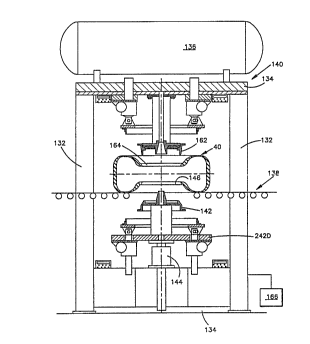
A tire 40 that is to be corrected is transported to a
correction station 140 embodying the present invention, as
illustrated in Fig. 6. The correction station 140 includes
vertical frame members 132 as well as upper and lower cross
members 134. An air tank 136 may be mounted to the upper
cross member 134. The mode of transportation of the tire 40
may be manual or automated on a conveyor system 138. The tire
40 is initially supported in the correction station 140 in
WO93/1~29 PCT/EP93/~7~r
~1~2~ 16 -
the position illustrated in Fig. 6. It should be apparent
that the correction station 140 could be a stand alone
operation or be incorporated into a tire uniformity test
machine for a combination test and correct operation.
A lower simulated rim mounting 142 is moved upwardly by a
main actuator 144 from the position illustrated in Fig. 6
towards the position illustrated in Fig. 7. The lower
simulated rim mounting 142 (Fig. 6) is brought into axial
engagement with the lower bead area 146 of the tire 40. The
main actuator 144 continues to raise the tire 40 away from
the conveyor 138. The tire 40 then is forced against the
upper simulated rim mounting 162 at the upper bead area 164,
as illustrated in Figs. 7 and 8. The tire 40 is inflated with
fluid pressure, such as air, to a pressure sufficient to seat
the bead areas 146, 164 of the tire 40 against the simulated
rim mountings 142, 162. Then the tire 40 is deflated to a
relatively low pressure which is above the surrounding
ambient atmospheric pressure and which pressure is
approximately equal to one-tenth the recommended operating
pressure of the tire.
Once the tire 40 is located in the correction station 140, a
programmable controller l66 (Fig.6) operably connected with
the correction station 140 and computer determines, in
operation 202 (Fig. 14) by a variety of inputs, if conicity
correction, radial force variation correction or both is to
be performed. At the tire correction station 140 the tire 40
has an indicator, such as a bar code label or an infrared ink
identification which is read and indicates information about
the tire 40 to the controller 166. Such information may be,
for example, information related to reference measurements
(i.e. soft spot or hard spot) or a unique identifier, such as
a serial number which is communicated to the controller 166.
The controller 166 can then input data associated with that
~ - 17 -
serial number, such as the type of uniformity characteristic
to be corrected as well as the wave forms and analysis that
were stored in the computer in operation 87 (Fig. 1). Once
this information is known to the controller 166 the tire 40
located in the correction station 140 can be corrected.
If the controller 166 and control program determine that
radial force variation of the tire 40 is to be corrected in
operation 202 (Fig.14), the controller and control program
determine which radial force variation, composite or harmonic,
is to be corrected in operation 208. If for example, an
operator or the control program has indicated, in operation
208, that the first harmonic of the radial force variation is
the desired harmonic to be corrected, operation 220 sets
input parameters, to be used in a later operation, indicating
the first harmonic. Alternatively, operation 220 can be
programmed to select the harmonic of the radial force
variation to be corrected as a function of a predetermined
parameter, such as the harmonic with the greatest magnitude.
Once it is determined that one or more harmonics of the
radial force variation is to be corrected, operation 221
analyzes or reads the stored harmonic wave forms as
illustrated in Fig. 3.
If the first harmonic of the radial force variation is to be
corrected as determined in operation 220, an analysis of the
first harmonic wave form (if it has not been analyzed
already) is performed in operation 221. The analysis may have
already been done in operation 87 (Fig. 1) and stored for
use at this time. The analysis will now be described in detail
for a better understanding of such analysis. The analysis can
be better understood with reference to Fig. 3. In Fig. 3, the
initial first harmonic wave form signal for the uncorrected
tire 40, as tested, is illustrated. Only two radial force
variation input parameters are required to initiate the first
A'
I
~V093/1~29 PCT/EP93/007~-
2 1 0 ~ 18
harmonic correction. The magnitude 238 and the location 236
from a reference location provide these parameters. The
magnitude is the difference between the soft spot 232
magnitude and the hard spot 234 magnitude. The location is
the angular position 236 of the soft spot 232 from the
reference. These two parameters are obtained in operations
221 and 222 of Fig. 14, and/or operation 87 of Fig. 1.
This peak-to-peak magnitude 238 may be graphically
represented as, for example, approximately 4.55 daN, of first
harmonic desired correction (Fig. 3). If, for example, the
tire 40 has four daN first harmonic peak-to-peak radial force
variation or less, and which four daN may be the minimum
threshold acceptable limit for magnitude, the tire 40 would
-be shipped to the customer. If the relatively large maximum
threshold limit for scrapping the tire 40 is greater than or
equal to, for example, 10 daN first harmonic peak-to-peak
magnitude, the tire would be scrapped. Here it is apparent
that the 4.55 daN approximate peak-to-peak magnitude 238 of
first harmonic radial force variation is within the
predetermined range of peak-to-peak magnitudes of four daN to
ten daN and, thus, the tire 40 is suitable for correction.
The analysis operation 221 also includes the location 236 of
the first harmonic soft spot 232 around the tire 40 as an
angular position from a physical reference on the tire 40.
Thus, the location 236 of the first harmonic soft spot 232 is
known to operation 222 (Fig. 14). The magnitude 238 and
location 236 of the soft spot are used as input parameters to
determine control parameters for the correction operation 258.
Correction of the uniformity characteristic is accomplished
in operation 258 (Fig. 14) by permanently deforming at least
one, and preferably many, carcass reinforcing members. The
stretching is done preferably by applying relatively high
'''093/1~29 2 ~ PCT/EP93/~745
-- 19 --
inflation pressure to the interior of the tire 40 for a
predetermined time. Input parameters are preferably used in
operation 206 to determine control parameters for the
correction operation 258. The control parameters are known to
the controller 166 before the correction operation 258 is
initiated. The input parameter of magnitude 238 affects the
determination of control parameters such as deflection, time
and pressure (or force) which are applied to the tire 40. The
input parameter of location 236 (Fig. 3) of the soft spot
affects the positioning of the tire 40 in the correction
station 140. Other input parameters affecting the control
parameter such as deflection, time and pressure applied to
the tire 40 include the type and properties of material of
the carcass reinforcing member. An example of properties
include diameter, pitch and number of filaments used in the
carcass reinforcing member. Materials of the carcass
reinforcing member such as nylon and polyester are readily
adaptable to correction by the present invention. Materials
such as steel, Kevlar and rayon are not as easily permanently
elongated and may require higher pressure or longer hold
time.
A signal is generated by the controller 166 which is
indicative of at least the magnitude 238 (Fig. 3) of
correction desired and the angular location 236 from a
reference on the tire 40 to be corrected. The signal may be
hydraulic, pneumatic or preferably electronic. When the tire
40 is delivered to the correction station 140, the
orientation of the tire may be accomplished relative to a
known location on the correction station. For example, as
illustrated in Fig. 6 if a first harmonic radial force
variation correction is needed the location 236 of the first
harmonic soft spot 232 is positioned at the far left hand
side of the correction station 140, as viewed in Fig. 6. This
positioning can be done by first marking the soft spot on the
WO 93/1992g PCI'/EP93/007~r
~ Jb1~ ~ 20 -
tire 40 relative to the physical reference of the tire 40
an angular amount equal to the location 236 in degrees.
With the tire 40 properly located and initially inflated, the
correction station 140 is then further activated to assume
the position illustrated in Fig. 7. The correction station
140 includes at least one restraint ring 182 which is brought
into engagement with at least one corresponding sidewall of
the tire 40. The number and type of restraint rings 182
brought into engagement with the sidewall or sidewalls of the
tire 40 is determined as a control parameter in operation 206
as a function of the type correction desired in operation
258. If the first harmonic of radial force variation is to be
corrected, then both the upper restraint ring 182U and lower
restraint ring 182D engage the respective sidewalls of the
tire 40.
Correcting a first harmonic radial force variation includes
inflating the tire 40 to a pressure above the recommended
- operating pressure of the tire 40 as a function of input
parameters while restraining a portion of the sidewall to
control the distribution of the correction around the tire.
Stretching and permanently lengthening a portion of the
carcass reinforcing mem~er at different locations around the
tire can correct the uniformity characteristic of the tire
40. Permanent deformation or elongation L is achieved by
stretching a carcass reinforcing member beyond its elastic
limit and holding it for a predetermined time, as illustrated
in Fig. 20. The distribution of the amount of lengthening is
controlled by restraining the sidewall of the tire 40 by an
amount that varies around the circumference of the tire. This
varying circumferential stretching is a function of the
uniformity characteristic being corrected and other
parameters.
'''093/1~29 2 ~ S 1~ ~ ~ 3 PCT/EP93/00745
Restraint rings 182 (Fig. 8) engage the sidewalls with
different axial displacements Dl, D2 to impart a different
radius of curvature R1, R2 to the portion of the carcass
reinforcing member 306 (Fig.9) in each of the sidewalls. The
restraint rings 182 are used preferably only when inflation
pressure is used for correction. The radius of curvature R2
in a maximally restrained portion of the tire 40
corresponding to displacement D2 is significantly less than
radius of curvature R1 in the minimally restrained portion of
the tire corresponding to displacement D1. Different radii of
curvature provide different tension values in respective
carcass reinforcing members.
The maximum amount of restraint to be applied for first
harmonic radial force variation correction is at the first
harmonic hard spot 234 on the tire 40 at a location 180~ away
from the location 236 of the first harmonic soft spot 232
indicated by the signal. The maximum restraint occurs at the
location of maximum axial displacement D2 relative to the
mid-circumferential plane M of the tire 40 which is to the
far right in the correction station 140, as viewed in Fig. 7.
A minimum amount of restraint, or no restraint at all (i.e. a
gap) is applied to the sidewalls of the tire 40 at the
location of the first ha-rmonic soft spot 232 indicated by the
signal and known to the controller 166 and correction station
140. The minimum restraint occurs at the location of minimum
axial displacement D1 relative to the mid-circumferential
plane M of the tire 40. This is at the far left of the
correction station, as viewed in Fig. 7. It will be explained
that more correction to the tire 40 occurs at the location of
minimum restraint and relatively less (or no) correction
occurs at the location of maximum restraint.
Fig. 10 is a schematic illustration of one carcass
reinforcing member 306 being corrected according to the
WO93/1~29 PCT/EP93/0074-
2102~1~ 22 -
preferred embodiment of the present invention. A portion 302
of the carcass reinforcing member 306 is illustrated in
Fig. lo by a dashed line prior to being restrained. This
portion 302 of the carcass reinforcing member 306 has an
upper end point 304 at which load in the carcass reinforcing
member is transmitted to the belt package 46 of the tire 40.
The portion 302 of the carcass reinforcing member 306 has a
lower end point 308 in the area of the bead 42 (Fig. 9) at
which load in the carcass reinforcing member is transmitted
to the bead of the tire 40. The deflected portions 312 of the
portion 302 of the carcass reinforcing member 306 are
illustrated in Fig. 10 in solid line. The deflection distance
310 is illustrated in Fig. 10 to correspond to the maximum
amount of restraint discussed above in terms of
deflection D2.
In the deflected portions 312 of the carcass reinforcing
member 306 it will be apparent that the original or
unrestrained radius of curvature R1 of the carcass
reinforcing member has changed and is now a relatively
smaller radius of curvature R2 in two locations. Physically
the smaller radius R2 of portion 312, when the interior of
the tire 40 is subjected to the same relatively high
inflation pressure, such-as 100 psi or 7 bars, will not be
permanently elongated the same amount as the unrestrained
portion 302 of the carcass reinforcing member 306 having the
relatively larger radius of curvature R1. The relationship
between tension in the carcass reinforcing member 306, radius
of curvature in the reinforcing member 306 and inflation
pressure in the tire 40 can be represented by the formula
T = R.P, where T is the tension force in the portion 302 of
the carcass reinforcing member 306, R is the radius of
curvature of the portion 302 or 312 of the carcass
reinforcing member 306 and P is the internal inflation
pressure in the tire 40 causing tension in the portion 302 of
. . .
0 93/1~29 2 1 0 ~ PCT/EP93/~745
- 23 -
the carcass reinforcing member 306. Thus, it will be apparent
that for a constant inflation pressure P, the larger radius
of curvature R of the portion 302 of the carcass reinforcing
member 306, results in a relatively higher tension T acting
on that portion of the carcass reinforcing member. Thus, the
higher tension in the portion 302 of the carcass reinforcing
member 306 generally results in a relatively greater
elongation above the elastic limit of the material which
results in permanent elongation. The larger radius of
curvature R1 in the portion 302 occurs at the location of
minimum restraint around the tire 40 with a planar ring
restraint device.
The restraint rings 182 may be of any configuration desired
that is suitable for the type correction to be performed and
as a function of the parameters determined in operation 206.
For example, as illustrated in Fig. 8, a pair of restraint
rings 182 are brought into engagement with the sidewalls of
the tire 40 from axially opposite sidewall sides. The
restraint difference is accomplished at the correction
station 140 by axially moving the restraint rings 182
different amounts relative to the mid-circumferential plane M
of the tire 40 at diametrically opposite regions of the tire.
The axial movement of the restraint rings 182 is performed at
the far left and far right in the correction station 140 by
two pairs of actuators 246 (Fig. 7). The lower restraint ring
182D is supported at diametrically opposed end portions by a
pair of actuators 246, each of which is driven by a
respective motor 244. The lower actuators 246 are movable
axially relative to a lower support 242D. The support 242D
has the motors 244 attached directly thereto. Upon actuation
of one of the motors 244, an associated actuator 246 moves
the lower restraint ring 182D axially toward or away from the
tire 40 in a direction parallel to the axis of rotation A of
the tire. The upper restraint ring 182U is supported and
WO93/1~29 ~
~ PCT/EPg3/~7~-
210~ 24 -
moved similarly relative to the upper cross member 134 and
support 242U.
The controller 166 and control program determine the amount
of restraint or displacement needed at the location 236 of
the first harmonic soft spot 232 of the tire 40 as a control
parameter in operation 206. The control parameters are
preferably determined by a look up table in operation 206 as
a function of the magnitude 238 of correction to be applied
to the tire 40 and other input parameters. The look up table
can be constantly updated to reflect the history of
previously corrected tires. The amount of restraint is
defined by the amount of axially inward deflection applied to
a sidewall of the tire 40. For example, the maximum amount of
desired deflection D2 at the hard spot may be 15 millimeters
as determined by the controller 166 and control program in
operation 258. The sidewalls of the tire 40 on the right
side, as viewed in Fig. 7, each are deflected axially 15
millimeters inwardly. This may be done manually or under
controller 166 and control program direction and verified by
digital output display 248R to indicate 15 millimeters of
deflection D2. The minimum amount of restraint is applied to
the sidewalls on the far left, as viewed in Fig. 7. For
example, the minimum amount of restraint may be 0 to 5
millimeters deflection Dl as verified in the digital output
displays 248L or may even be a gap of 0 to 10 millimeters. It
will be apparent that the restraint rings 182 are tilted
relative to the mid-circumferential plane M of the tire 40 to
be closer together at the far right of the correction station
140, as viewed in Fig. 7. If a gap is initially provided, it
will generally close by the sidewall contacting the restraint
ring 182 as the tire 40 is inflated.
The maximum amount of deflection may be 15 millimeters in the
axial direction. This means that each sidewall of the tire 40
'''~93/1~29 21~ 18 PCT/EP93/00745
- 25 -
is deflected a distance D2 axially inwardly against the
relatively low initial inflation pressure, such as 3 to 5
psi. The minimum amount of restraint may be 0 to 5
millimeters of axial deflection Dl of the sidewall at the
location 236 of the first harmonic soft spot 232 (Fig. 3).
The inflation pressure of the tire 40 is then raised
significantly to a predetermined pressure above the
recommended operating pressure of the tire, for example 100
psi or 7 bars, and held for a predetermined hold time. The
minimum predetermined pressure is preferably in the range of
two to three times the operating pressure of the tire 40. The
predetermined hold time may be, for example, 10 seconds but
will be considerably shorter than a cure cycle period. The
minimum predetermined hold time is preferably at least one
second. The input parameters as to amount of deflection,
inflation pressure and hold time can be selected and varied
by the controller 166 and control program in operations 258
(Fig. 14) as a function of the magnitude of uniformity
characteristic correction needed, the size of the tire, the
properties of the tire and the intended application of the
tire.
This relatively high predetermined pressure forces the
carcass reinforcing mem~ers 306 (Fig.9) of the tire 40 to
react to the elevated internal pressure and increase the
tension in each carcass reinforcing member which results in
lengthening. This increased tension and lengthening, when
held even for a relatively short period of time above the
elastic limit of the carcass reinforcing member 306, as
illustrated in Fig. 20, results in the permanent deformation
- L by stretching of the carcass reinforcing members 306. The
carcass reinforcing members 306 which have no or minimal
restraint at the soft spot 232 on the left side of the
correction station 140 are permanently deformed the greatest
amount. Less permanent-deformation occurs gradually in both
WO93/1~29 PCT/EP93/~7
~ 10~ ~ 26 -
circumferential directions towards the hard spot 234 located
on the right side of the correction station 180~ from the
soft spot 232. The least amount of deformation occurs at the
location of maximum restraint at the hard spot 234. The
permanently longer each carcass reinforcing member 306 gets
relative to its prestretch length, the "harder" it becomes in
terms of radial force variation due to its permanent
elongation. A belt restraint ring 280 (Fig. 8) may be
optionally provided to counteract the relatively high
inflation pressures so that the belt package 46 is not
excessively expanded in the circumferential direction.
Figs. 4 and 5 illustrate the same tire 40 after correction
for first harmonic radial force variation. It will be
apparent that the relative magnitude as defined by
peak-to-peak magnitudes of the corresponding composite and
first harmonic wave forms are dramatically lower in the wave
forms of corrected tire 40 as illustrated in Figs. 4 and 5
than in the initial wave forms of the uncorrected tire as
illustrated in Figs. 2 and 3. Also illustrated in Fig. 4 is a
curve after the tire 40 has been in service for a
predetermined amount of time as would occur after, for
example, 1,000 miles of service. This illustrates that the
uniformity correction is permanent.
Another physical representation of what actually occurs when
the first harmonic radial force variation of the tire 40 has
been corrected according to the present invention is
illus~rated in Fig. 13. It is known that radial runout of the
tire 40 affects the radial force variation. Such a radial
runout is exaggerated in Fig. 13, as the outer circumference
322 of the tire 40 in dashed line. The radius RRl on the
right side of the tire 40 in relation to the center of
rotation 320 of the tire 40 established by the beads 42 is
relatively smaller than the radius RR2 on the left side. The
''~93/1~29 21 ~ 2 ~ ~ $ PCT/EP93/00745
- 27 -
portion of the tire 40 at the far most location to the right
would be deemed to be the location 236 of the soft spot 232
of the tire which would lend itself to first harmonic radial
force variation correction.
During correction according to the present invention, the
radius RRl is increased over a right most portion 326 of the
outer circumference 322 of the tire 40 to a radius RR3 due to
the relatively greater elongation of carcass reinforcing
members in the vicinity of the soft spot 232. The radius RR2
is reduced to a radius RR4. The belt package 46 is relatively
inextensible and the outer circumference of the tire 40 does
not increase. However, the location of the entire tread or
outer circumference of the tire shifts to the right, as
viewed in Fig. 13. This radial runout correction allows the
now relatively uniform radii RR3, RR4 to establish new outer
circumference 324 (solid line) relative to the center of
rotation 320 for the corrected tire 40. This radial runout
correction frequently reduces the magnitude of the first
harmonic radial force variation a sufficient amount to be
deemed acceptable. However, when the first harmonic radial
force variation is caused by tire attributes other than
radial runout, it may be necessary to introduce a radial
runout to reduce the magnitude of the first harmonic radial
force variation.
What has actually taken place during the correction operation
258 (Fig. 14) in this physical representation, is correction
by introducing a radial runout to the tire 40. This
introduced radial runout offsets the first harmonic radial
force variation regardless of the attribute of the tire 40
producing the radial force variation. While the corrected
radii RR3,RR4 are not exactly equal necessarily, the
resulting radial force variation (be it composite or first
harmonic) is reduced during rotation of the tire 40.
WO93/1~29 PCT/EP93/007~-
- 28 -
~1 0~ 3
The correction has been introduced over the portion 326 of
the tire 40 by maximally permanently elongating portions 302
of the carcass reinforcing members 306 located in both
sidewalls of the tire 40 (Figs. 9 and 10). The portions 312
of carcass reinforcing members 306 in the sidewalls of the
tire 40 that were minimally permanently elongated or not
elongated at all were restrained by the restraint rings 182
as described above. For example, the restraint rings 182
would place the maximum amount of restraint and maximum
deflection at the left most portion of the sidewall of the
tire 40, as viewed in Fig. 13. This portion of the tire 40
corresponds to the location of the first harmonic hard spot
234. At the same time, minimum restraint and minimum
deflection or even a gap would be allowed at the right most
portion of the sidewall, as viewed in Fig. 13. This portion
of the tire 40 corresponds to the location 236 of the first
harmonic soft spot 232. When the restrained tire 40 is
inflated to a predetermined pressure, as described above, and
held for a predetermined time, the portions 302 of the
carcass reinforcing members 306 in the minimally restrained
portions of the tire are permanently elongated by an amount
greater than in the maximally restrained portions 312 of the
tire.
The procedure described above corrects the first harmonic of
the radial force variation associated with the location 236
of the soft spot 232 indicated by the signal generated by the
controller 166. However, if the second, third, fourth or
greater harmonics of radial force variation is desired to be
corrected, the location and number of minimum restraints mus'
be varied on the sidewalls of the tire 40 during subsequent
inflation and correction operations. For example, for the
second harmonic of radial force variation to be corrected
based on the wave form illustrated in Fig. 3 the amount of
~93/1~29 ~ 8 PCT/EP93/00745
- 29 -
minimum restraint would be at two different locations 237 of
second harmonic soft spots 233 from the location 236 of the
first harmonic soft spot 232. Typically, the maximum amount
of restraint as a function of the magnitude at the location
indicated by the signal generated by the controller 166 will
likely be less for the second harmonic than for the first
harmonic. The maximum restraint can be maintained in the
controller 166 and control program as a function of the
second harmonic peak-to-peak magnitude. It should be apparent
that higher order harmonics of the radial force variation
would be corrected in a manner similar to that described for
the first and second harmonics.
Another correction option in operation 208 (Fig. 14) is that
of composite radial force variation correction. In operation
210 the hard spot 214 (Fig. 2) of the composite radial force
variation of the tire 40 is identified as well as its
location 215 relative to a physical reference on the tire.
The location 216 of the composite soft spot 212 is also
identified in the controller 166 and control program. The
controller 166 and control program determine or read the
composite peak-to-peak magnitude which is represented by a
distance 218 to be approximately 7 daN. The magnitude 218 and
the location 216 of the soft spot 212 may be used as input
parameters for the correction operation 258 (Fig. 14) if the
magnitude falls within a predetermined range of magnitudes
deemed appropriate for correction. For example, the range may
be six daN to 12 daN.
It should be apparent, in the wave forms illustrated in
Figs. 2 and 3, that the locations 216,236 of the respective
soft spots 212, 232 may be offset relative to one another.
This results because the Fourier analysis defines the
locations of the soft spot and hard spot of, for example, the
first harmonic wave form as being 180~ apart. Similar even
WO93/1~29 PCT/EP93/007~-
~1 ~.3~ ~ 8
spacing of the respective adjacent soft and hard spots of the
other harmonic wave forms also occur. It should also be
apparent that the soft spot 212 of the composite wave form is
not necessarily spaced 180~ from the hard spot 214 but occurs
as sensed during testing. For example, in the composite wave
form illustrated in Fig. 2, the soft spot 212 is spaced
approximately 150~ from the hard spot 214.
If composite radial force variation correction is desired,
the location 216 of the soft spot 212 of the composite radial
force variation is positioned at the far left hand side of
the correction station 140, as viewed in Fig. 6. This
positioning can be done by first marking the tire 40 so the
soft spot 212 is located angularly from the physical
reference. A first order composite radial force variation
correction is performed as outlined in operation 258 (Fig.
14) and as described above for first harmonic correction. The
correction involves permanent elongation of portions of
carcass reinforcing members 306, preferably by increasing the
inflation pressure of the tire 40 considerably above the
recommended operating pressure of the tire and holding that
increased pressure for a predetermined hold time.
The maximum amount of restraint for composite radial force
variation correction should be at the composite hard spot 214
on the tire 40. However, for the composite wave form
illustrated in Fig.2, the location 215 of the hard spot 214
is 150~ away from the location 216 of the soft spot 212. The
maximum restraint of the "first harmonic" restraint rings 182
will occur at the location 180~ from the location 216 of the
composite soft spot 212 when the restraint ring 182,
described above, is used. A minimum amount of restraint, no
restraint or a gap is applied to the sidewalls of the tire 40
at the location 216 of the soft spot 212, 217 indicated by
the signal and known to the controller 166 at the correction
'"~93/1~29 21 ~ 2 ~1 ~ PCT/EP93/~745
- 31 -
station 140. Thus, some trade off in the location of maximum
restraint occurs due to the use of the first harmonic
restraint rings 182.
As an alternative embodiment, a restraint ring 380 (Fig. 21)
can be used which has a cupped segment 383 which is not in a
plane containing the planar surface 384. For example, the
cupped segment 383 preferably extends over a 90 degree arc
length of the restraint ring 380. The cupped segment 383
provides nonlinear restraint to the tire 40. Such a cupped
restraint ring 380 can be used to correct composite radial
force variation as illustrated in Fig. 2, by relatively
positioning the cupped segment 383 relative to a soft spot
212 or 217. With several (two for the wave form illustrated
in Fig. 2) different angular locations of the restraint ring
380 and associated inflation pressure cycles for the same
tire 40, the composite radial force variation of the tire can
be effectively corrected. It is apparent that the shape of
the surface of restraint ring 380, namely the number, size
and position of segments 383, can be selected to give any
predetermined restraint ring shape within the scope of this
invention. However, the maximum correction will still occur
at the soft spot 212 because minimal restraint (~xirum
cupping) can be applied-at the loc~tion 216. Other restraint
devices could be developed to optimize the location of
maximum restraint.
If the controller 166 and control program, as illustrated in
Fig. 14, determine that the tire 40 is to be corrected for
conicity in operation 202, the location or side of the tire
40 requiring thecorrection is identified in operation 204 to
the controller. The location or side of the tire requiring
correction is a function of the direction of conicity. The
parameters as to the location or side of the tire 40 and the
magnitude of correction required by the tire 40 are used by
WO93/1~29 PCT/EP93/007~-
f~l ~2~1~ ~ 32 -
the controller 166 and control program in the correction
operation 208. These parameters are input to operation 206
and stored for the correction operation 258 for each tire 40
to be corrected.
In order to correct conicity of the tire 40 in the correction
station 140 illustrated in Fig. 7 the following procedure is
performed. If the side of the tire 40 to be corrected for
conicity is located facing upwardly in the correction station
140, then no restraint will be applied to the upwardly
facing sidewall of the tire. The lower restraint ring 182D is
brought into engagement with the lower sidewall of the tire
40. The lower restraint ring is 182D moved axially inwardly a
substantially equal amount over the entire planar contact
surface of the restraint ring 182D. Thus, the lower restraint
ring 182D is not tilted and the upper restraint ring 182U
does not engage the tire 40. However, it will be apparent
that two restraint rings 182 could be used for conicity
correction with different amounts of restraint used on the
different sidewalls of the tire 40, as described herein
below.
When the proper amount of deflection or restraint has been
applied to the lower sidewall of the tire 40 by the restraint
ring 182D, correction for conicity may be initiated. The
internal pressure of the tire 40 is then elevated to an
amount sufficient to produce a desired permanent elongation
in the carcass reinforcing members 306 in one sidewall of the
tire. Such a pressure may be, for example, 100 psi or 7 bars.
The deflection and elevated internal pressure is held for a
relatively short period of time, for example, for ten
seconds. The tire 40 is then deflated and the restraint
removed from the lower sidewall of the tire and the tire is
removed from the correction station 140. The conicity
correction has occurred in the portions of the carcass
'''093/1~29 ~ ~ 2 ~1 ~ PCT/EP93/~745
- 33 -
reinforcing members in the upper sidewall of the tire 40
which was not restrained. All of the portions of the carcass
reinforcing members in the upper sidewall of the tire were
permanently stretched preferably by an equal amount. The belt
restraint ring 280 may be used to keep the tread 62 of the
tire 40 from moving axially during conicity correction.
It will be apparent that if the lower sidewall of the tire 40
as it is placed in the correction station 140 needed
correction, then the upper sidewall of the tire would be
restrained by deflecting it axially inwards. It should also
be apparent that depending on the amount and location of
conicity desired to be corrected, that the restraint rings
182D, 182U could both engage opposite sidewalls of the tire
to apply differing deflection based on the magnitude of
correction desired. Thus, the inflation and hold procedure
can take place and correct both sidewalls by differing
amounts. It will also be apparent that one restraint ring 182
could be tilted if the magnitude of the conicity signal to be
corrected is not a constant amount circumferentially around
the tire 40.
If a conicity characteristic is to be corrected, the side of
the tire 40 needing the correction is identified to the
controller 166 and control program. No special angular
orientation of the tire 40 is generally needed if a conicity
characteristic is to be corrected. The side of the tire 40
needing correction and the amount or magnitude of correction
required must be known for conicity characteristic correction
on the correction station 140 of the present invention.
The restraint rings 182 each preferably have a flat or planar
surface 260 (Fig. 8) for use in correction of the first
harmonic or composite of radial force variation or in
correction of conicity. Each restraint ring 182 has a radial
WO93/1~29 PCT/EP93/007
- 34 - -
2 1 ~
length of engagement LE1 (Fig. 9) with the sidewall of the
tire 40 which is a relatively small percentage of the section
height SH (Fig. 8) of the tire. The edges 278 of the
restraint ring 182 may be rounded to avoid sharp edges. The
restraint ring 402 may also have a radial length of
engagement LE2 (Fig. 15) that is a relatively large
percentage of the section height SH of the tire 40.
If a restraint ring 380 (Fig. 21) is provided with a cupped
or concave surface in one or more locations, then other
harmonics may be corrected during one correction operation.
Such a restraint ring 380 is described above and may have a
cupped portion 383 over 90~ of the surface 384 (Fig.23). This
allows correction of, for example, first and second harmonics
of radial force variation when the soft spot of the second
harmonic is located away from the soft spot of the first
harmonic. The placement of the restraint ring 380 against the
tire 40 is determined by the controller 166 to be optimal
under program parameters.
The amount of permanent deformation to the carcass
reinforcing members 306 occurs by stretching a portion 302 or
312 of the carcass reinforcing member which is preferably
located in a sidewall of- the tire beyond its elastic limit
(Fig. 10). This may be done by stretching the cord
permanently in the range of 0.1 to 2 or 3 percent or some
predetermined amount as a function of the magnitude of
uniformity characteristic desired to be corrected, and the
material of the carcass reinforcing member. The results of a
first harmonic linear correction by 5 millimeters minimum
restraint and 15 millimeters maximum restraint is illustrated
Fig. 12. The tire 40 was exposed to 100 psi (7 bars) of
internal pressure for ten seconds of hold time with a planar
surface restraint ring 182. It has been observed that for a
passenger car tire, one percent of permanent elongation of
''~93/1~29 _ 35 _ PCT/EP93/00745
the carcass reinforcing member 306 between the points 304 and
308 (Fig. 10) at the first harmonic soft spot and zero
percent at the hard spot results in approximately 10 daN of
first harmonic radial force variation.
An alternate restraint device 388 is illustrated in Fig. 11.
A portion of the sidewall of the tire 40 is restrained
without a deflection. The restraint device 388 comprises two
portions 394 that contact the tire 40 at two radial locations
390, 392. These radial locations 390, 392 contact the outer
surface of the sidewall of the tire 40. The portions 394 of
the restraint device 388 are spaced equally from the
equatorial plane E. The sidewall of the tire 40 has an
unrestrained length 396 which is deflected by the inflation
pressure. The unrestrained length 396 has a minimum dimension
associated with the hard spot and a maximum dimension
associated with the soft spot. The unrestrained length 396 of
the restraint device 388 varies circumferentially around the
tire from the hard spot to the soft spot, as illustrated in
Fig. 22. The carcass reinforcing members are permanently
elongated during inflation a greater amount where the
unrestrained length 396 has a larger dimension.
The restraint device 388 has interconnecting parts 398 so
that the portions 394 in contact with the tire can act as one
device. This restraint device 388 allows the carcass
reinforcing members to have a deflection 316 and a radius of
curvature R4 which is smaller than the initial unrestrained
radius of curvature Rl under the influence of inflation
pressure.
Fig. 15 illustrates a flat surface restraint ring 402 having
a radial length of engagement LE2 which is a relatively large
percent of the section height SH of the tire for a radial
length of engagement. This yields a radius of curvature R3
WO93/1~29 i PCT/EP93/007~-
~2~ 36 -
which is less than the initial radius of curvature Rl.
Fig. 16 corresponds to a schematic illustration of what
occurs to the portion 422 of the carcass reinforcing member
during correction under relatively high pressure with the
restraint ring 402.
Figs. 17 and 18 similarly schematically illustrate an
alternative method and apparatus for use without an inflation
pressure increase in the tire 40. The devices 502, 504, 506
mechanically stretch portions 512 of the carcass reinforcing
member axially outwardly beyond its elastic limit. Fig. 19 is
another schematic illustration of mechanically stretching a
portion 602 of the carcass reinforcing member beyond its
elastic limit. This is done by radially stretching the
portion 602 of the carcass reinforcing member between the
upper and lower attachment points 604, 606 in the sidewall of
the tire 40. Deflection 608 of the portion 602 results. This
stretching could be accomplished by moving point 606 radially
inward, and point 604 radially outward or by moving point 604
radially outward. It should be apparent that stretching of
the portion of carcass reinforcing members could be
accomplished by a combination of mechanical stretching and by
inflation pressure stretching.
The following is an example of a radial force variation
correction performed in accordance with the method and
apparatus of the present invention.
"~93/1~29 ~ a ~ PCT/EW3/00745
TEST RESULTS OF CORRECTED TIRES
3mm Maximum Restraint Deflection
6mm GAP Minimum Restraint
10 Second Hold Time
Before After Treatment
Tire Correction Correction Improvement Pressure_(bar)
1 3.7 daN 2.0 daN 1.7 daN 7.5
2 4.6 2.3 2.3 8.0
3 5.4 2.5 2.9 8.5
4 3.3 1.5 1.8 7.25
5.1 2.0 3.1 8.25
6 2.8 0.8 2.0 7.0
7 4.7 2.3 2.6 8.0
8 4.9 2.3 2.6 8.0
9 4.2 1.2 3.0 7.75
6.0 1.8 4.2 8.5
AVG 4.47 1.87 2.60
The tire used for test purposes was a Michelin
205/70R15 XZ4 tire. It can be seen that a 58 percent average
reduction of first harmonic radial force variation in the
sample has occurred. This is a significant portion of the
first harmonic radial force variation and the tire 40 so
corrected will provide a dramatically improved ride when it
is on the vehicle than ~f it had not been corrected. The
correction occurred without grinding of the tire 40 and in a
relatively short period of time.
From the above description of preferred embodiments of the
invention, those skilled in the art will perceive
improvements, changes and modifications. Such improvements,
changes and modifications within the skill of the art are
intended to be covered by the appended claims.