Note: Descriptions are shown in the official language in which they were submitted.
21027 4~
ADAPTIVE FURNACE CONTROL USING
ANALOG TEMPERATURE SENSING
FIELD OF THE INVENTION
s The present invention pertains to a furnace control. More particularly,
it pertains to a furnace control which utilizes the sensed air temperature in the furnace
heat exchanger to control furnace output and the ratio of on/off time of each furnace
cycle to control circulation blower speed.
BACKGROUNDOFTHEINVENTION
Most forced warm air central heating systems utilize a standard furnace
to heat air which is heated within a heat exchanger and forced through duct work to
areas which the furnace is to heat. Generally, this operation is based upon receiving a
control signal from a thermostat which is mounted in a remote location; normally, in
the area which is to be heated. The thermostat sends a control signal to the furnace
and turns the furnace on or off based upon the ambient air temperature of the room
which is heated. In this manner, the furnace cycles on and off, sending heated forced
air to the space which is heated. Most furnaces, however, operate at a fuel input rate
which provides significantly more heat than is necessary. In residential use, most
2 o furnaces are designed to heat an entire house in a short period of time. These
furnaces are designed such that they may bring a house from a temperature well
below the desired temperature to the desired temperature rapidly. When a furnace is
being utilized strictly for the purpose of maintaining a specific temperature within a
house, which is the norrnal function of a furnace, most furnaces are operating at, or
about, 75% above the necessary fuel input level and, therefore, energy may be
wasted. The object of this invention is to increase energy efficiency and provide
improved temperature control (comfort) in the heated space.
SUMMARY OF THE INVENTION
3 o The invention is a system which uses an analog temperature sensor to
control furnace operation to obtain the following benefits:
improved economy,
more uniform temperature control,
improved air circulation when heating load is low,
3 s lower noise operation, and
increased furnace life.
The invention is particularly adapted for furnaces in single zone
systems. A multiple zone system is disclosed in co-pending, commonly owned,
! '. , . , ' ' . , : ' ' .
21027~B
- 2 -
Canadian patent application entitled "Adaptive Forced Warm Air Furnace Using
Analog Temperature and Pressure Sensors, " serial number , filed on the
same date as the present application, and is hereby incorporated by reference. In the
present single zone system, a control can be made to operate with only analog heat
exchanger temperature sensing. The heat exchanger temperature is used to controlthe firing rate. The circulation blower speed is adjusted every cycle, according to the
history of the ratio of on/off duty cycles.
The system utilizes a microprocessor to handle the blower speed;
however, control of the firing rate could very easily be done in an analog manner to
0 e1iminate the need for an A/D controller. In this scheme, a thermistor sensor in, or in -~
close proximity to, the heat exchanger senses temperature. A Modureg amplifier
controls a modulating valve to control the firing rate of the burner and holds the heat
exchanger temperature at a fixed setpoint. By changing the blower speed it is possible ; -
to control the heat delivery to match the heat load. Control of the blower is
accomplished from a history record of the furnace on/off cycles kept in the memory
of the microprocessor. At the beginning of each cycle the blower speed is adjusted to
a predetermined speed. That speed will be held during the first cycle. The control
algorithm is then determined empirically.
BRIEF DESCRlIrrION OF THE DRAWING
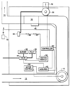
Figure 1 i11ustrates a typical furnace which incorporates the invention.
Figure 2 is a flow diagram showing the operation of the furnace.
DESCRIPllON OF THE PREFERRED EMBODIMENT
Figure 1 illustrates a furnace which incorporations the invention. The
furnace comprises a circulation bbwer 10, a burner 20 and an induced draft blower
30. In general, the operation of Applicants' invention is similar to a standard
furnace, wherein returned air from the ducts is brought into the return ducts 12 and
pressurized using blower 10 so tbat it is forced through heat exchanger 16, warm air
3 o ducts 14 and delivered to the area to be heated. Heat exchanger 16 is heated utilizing
burner 20; burner 20 generally utilizes either natural gas or oil. Burner 20 mixes and
burns fuel and air which is brought through the heat exchanger 16 by induced draft
blower 30. These combustion gases are then expelled out of the furnace through an
exhaust chimney 32.
3 5 In normal furnace operation, burner 20 is turned on and off from an
external control1er, generally a thermostat located in the space the operator wishes to
control the temperature. Burner 20 then runs at a preset level and blower 10 will run
at full speed, providing forced air to the heated space until the thermostat is satisfied.
". . . , .. ~ . . .. ... ... , .. . . . . .. .. , .. , . , . , . . . . . . . . .. . ~
~1~274~
- 3 -
In normal operation, the furnace has little or no control over heat exchanger
temperature and blower 10 speed.
Applicants' invention operates with a similar control utilizing the
thermostat; however, the thermostat does not control the speed of blower 10 or heat
exchanger 16 temperature. In the operation of Applicants' invention, a temperature
sensor 40, a thermistor, measures the temperature of heat exchanger 16 and provides
a signal to Modureg 42. Although Applicants uses a thermistor for temperature
sensor 40, any temperature sensitive means may be used, including, but not limited
to, variable resistive means, thermocouples, and bimetal sensors. Modureg 42
controls when burner 20 is on and off and at what level the burner is operating in
order to maintain a constant temperature at heat exchanger 16. Modureg 42,
regulates valve 44 and thereby modulates burner 20 such that heat exchanger 16 is
held at a constant temperature (e.g., 120F) during the "on" portion of the cycle.
Modureg 42 is a product that receives an input from a thermistor and thereby controls
1 5 a modulating gas valve accordingly. The valve control signal in this case is a variable
current provided by Modureg 42. The Modureg circuit utilized in this application is
manufactured by Honeywell Inc., Home and Building Controls Division. Valve 44
controls the fuel flow which is provided to burner 20 and to pilot 50. Pilot S0 is
ignited by ignition module 52. Although Applicants' invention utilizes Modureg 42,
2 o Modureg 42 could be replaced by any control system that will modulate valve 44
proportional to heat exchanger 16 temperature.
Blowers 10 and 30 are controlled utilizing controller 60 and provide
pressurized air for the forced air heating system and induced air draft across burner 20
respectively. A thermostat provides a request for heat through node A to controller
60. Controller 60 controls blower 10 through motor control 62. Motor control 62
regulates the speed at which blower 10 is operating. Blower 10 provides forced air
based on requests from the thermostat and an adaptive intelligence which allows
controller 60 and motor control 62 to track the length of the cycles so that constant
on/off cycles can be maintained. A microprocessor in controller 60 tracks thé length
3 o of the previous on/off cycles and increases or decreases blower 10 speed such that the
on/off cycles wUI be equal. More specifically, if the on cycle is shorter than the off
cycle, blower 10 speed will be decreased so that the desired area which is to be heated
is not heated as quickly, thus extending the length of the on cycle. If the on cycle,
however, is longer than the off cycle, the speed of blower 10 is increased
3 5 incrementally in order to heat the desired area faster, thus shortening the on cycle.
By making incremental changes, controller 60 and motor control 62 are able to
regulate blower 10 speed until equal on/off cycles are obtained.
: . '
.. . . ..
~ ., . . . ~ :
.. . . -. . . . .
~10274~
In the case of initial startup, or restart after a power outage, the
microprocessor located in controller 60 will not have a prior history with which to
regulate the speed of blower 10 based on previous on/off cycles. In this situation, the ~ -
system will start with maximum circulation blower speed and correct on the following
5 cycle in order to establish more uniform cycle rates. A known challenge in thealgorithm will be detecting setup and setback in handling these situations properly.
This will be accomplished by noting unusually long and short cycles. Enough history
must be kept to know how to handb these situations. Further, there will be some ~ ~ -
deviation from the algorithm due to the specific variables in the installation, closed
registers and clogged filters. To accommodate these situations, there should be a
manual adjustment of the authority of the control algorithm. Once that is done, the
automatic adjustment wil1 hold the on/off ratio quite constant and provide system
enhancements.
A voltage proportional to heat exchanger 16 temperature is fed to a
comparator to create an on/off signal to controller 60 for blower 10. This allows
blower 10 to run only when the air in duct 14 is warm enough to be comfortable.
The igdtion and primary safety of this system is provided by ignition
module 52. Although most ignition modules known to persons skilled in the art will
work satisfactorily for this invention, Applicants utilized a Model S89 ignition module
2 o produced by Honeywell Inc., Home and Building Controls Division.
Pressure switches 64 measure the differential pressures at induced draft
blower 30. Pressure switch 64 measures the air pressure differential created by
induced draft blower 30 with respect to the ambient air pressure. In this manner, the
furnace is able to determine whether there is an adequate induced air flow to operate
2 5 the furnace. If an insufficient induced air flow is present, contact 67 will open cutting
off power to ignition module 52 and closing valve 44. Contact 66 opens if heat
exchanger 16 temperature increases dramatically over the setpoint temperature,
generally 120F. Similar to relay 67, relay 66 shuts down ignition module 52 andcloses valve 44.
3 0 Figure 2 illustrates a flow chart for the operation of the furnace. The
furnace operates in a standby mode until a heating request is received from the
thermostat. Upon recehing a heating request from the thermostat, the furnace
records the last on/off cycle. The furnace then readjusts the circulation setpoint.
Induced draft blower 30 is energized by controller 60. Ignition module 52 is then
3 5 energized and valve 44 provides fuel to pilot 50. A thirty second period is then timed
out while the system checks to see if a pilot flame has been proven at pilot 50. If no
flame is proven after thirty seconds, valve 44 closes and the system shuts down.Upon a pilot flame being proven at pilot 50, main valve 44 provides fuel to burner
,: : ' ', ' ,' ;, ' , .' ' .' ,' , . '', .,'" ,' , ' ', . , ': ' .,. ' ' '' ' ' ' .. :' .~ ' . ' ': ' ,
:
210~746
~ 5
20, at which time pilot S0 ignites burner 20. A high fire period (to m~nimize
condensation) follows while heat exchanger 16 is heated. Upon heat exchanger 16
reaching an initial temperature of 90F, circulation blower 10 is energized by
control2er 60. Burner 20 continues at the maximum input rate until heat exchanger 16
5 reaches an operating temperature of 120F. Upon heat exchanger 16 reaching an
operating temperature of 120F, temperature sensor 40 alerts Modureg 42 which -
modulates valve 44 to burner 20 in order to keep a constant temperature of 120F at
heat exchanger 16. Upon the thermostat being satisfied, main valve 44 is turned off
to both burner 20 and pilot 50. Induced draft blower 30 is then de-energized by
controller 60. Heat exchanger 16 then cools to 90F at which time circulation blower
10 is de-energized, and the furnace returns to a standby condition.
:~ . ' .,, :
. .
. . , ~ . ,. ,~ :, .