Note: Descriptions are shown in the official language in which they were submitted.
Y09-92-120 1 ~s-~ ~2
DENTAL PROCEDURES ~MD APPARATUS USING
i ULTRAVIOLET RADIATION
,~
~ ,,
Field of the Invention
-- ' .:
This invention relates to improved procedures and
apparatus for procedures on teeth using ultraviolet
radiation, wherein ultraviolet laser pulses haviny
selected energy fluences can be used to perform several
different procedures on different materials found in
teeth.
Background Art
~
Lasers are optical devices which produce intense and
narrow beams of light at particular wavelengths by
stimulating the atoms or molecules in a lasing material.
Many types of lasing materials are known including gases,
liquids and solids. The lasers are typically named in
accordance with the element or compound that emits light
when energized, such as carbon dioxide, argon, copper
vapor, neodymium-doped yttrium-aluminum-garnet (Nd:YAG),
erbium, holmium,rare gas halide gas mixtures such as ArF,
XeCl, KrF (excimers) etc., alexandrite, ruby, Ti:sapphire -~
and many dyes. When applied -to human tissue, the beam of
light produced by the laser will be partially absorbed in
a process which typically converts the light to heat.
This is used to change the state of the tissue for
purposes of etching or cutting. In the case of
nonultraviolet radiation-producing lasers, the dominant ,`
mechanism for cutting or etching is a thermal one.
However, in the case of ultraviolet laser pulses having
energy fluences in excess of a threshold dependent upon
the wavelength of the radiation and the material being
irradiated, a "cool" etching is achieved in which there
is minimal heat transferred to the surrounding tissues.
Instead, the energy of the ultraviolet radiation pulses
is primarily transformed into the kinetic energy of the :
- "..
'. ~,';',
c~
Y09-92-120 2
particles which explode or ablate from the tissue being
irradia-ted. This fundamen-tal discovery and its
application for both medical and dental purposes is
described by S.E. Blum et al in US 4,784,135.
In the development of a laser system for specific dental
and medical applications, factors to be considered are
the wavelength of the light produced by the laser, the
pulse width of the radiation pulses, the energy per
pulse, the laser beam spot size on the target and the
apparatus and method of delivery of the laser light to
the tissue to be irradiated. It is necessary to deliver
a precise amount of light to the tissue, whether the
mechanism for cutting is a thermal one or ablative
photodecomposition as can be achieved through the use of
pulsed ultraviolet radiation. If there is application of
energy of high intensity to the tissue, rapid absorption
and heating can occur which can cause undue damage to
areas surrounding the irradiated region. In general,
pulse-type operation is preferred rather than continuous
wave irradiation, since delivery of a series of pulses
provides an additional control over the interaction,
absorption of radiation, and the overall process. This
leads to more control of the etch depth and the degree of
damage to surrounding tissue.
Medical research on the use of lasers has been ongoing
for many years. The use of lasers in the field of
ophthalmology to correct, for example, myopia, is the
subject of considerable research effort where good
success is noted. Many different types of lasers have
been used, with the more significant results now being
produced through the use of rare gas halide excimer
lasers providing pulsed ultraviolet radiation. In
addition to this application, lasers are now used in a
variety of medical applications such as gynecology,
urology, dermatology, angioplasty, and plastic surgery.
Lasers are also used in general surgery in connection
with surgical procedures concerning the ear, nose, and
throat as well as in the treatment of gastrointestinal
.,
~ ~~" Y09-92-120 3 ~ ~ ~ 2 ~
.. i
.
, ailments. The generally listed advantages of lasers for
;, some medical applications include reduced surgical pain,
~, reduced infection and bleeding, reduced scarring, and
3 less post-operative pain, as well as a reduced need for
post-operative analgesics.
. ,,
The use of lasers in dentistry has also been the subject
of considerable research and development activity. These
prior efforts have involved the controlled application of
laser thermal effects to soft or hard tissue. Problems
to be avoided in such laser dentistry include the
destruction of teeth by heat and often unsatisfactory
techniques for delivering the laser pulses into confined
~3 regions in the mouth. Various types of articulated arms
and fiber optic delivery systems have been developed for
these latter purposes. At this time, testing of various
~j types of laser systems in laser dentistry is occurring,
where the commonly used lasers are the Nd:YAG laser, C0
~i lasers, holmium lasers, argon lasers and erbium lasers.
:.~
Dentistry involves soft tissue procedures as well as hard
~3 tissue procedures. The soft tissue procedures include
-the removal of excess or diseased gum tissue, contouring
; of gums, performing biopsies, preparing gums for crown
and bridge impressions, trimming the gums to fit the
crowns and bridges, treating various types of gum disease
and infected pockets between the gum and teeth, and
"¦ hemostasis (control of bleeding). Hard tissue procedures
include drilling, removal of decay from teeth,
preparation of teeth for filling, increasing of hardness
.~ of dentin to render teeth less susceptible to decay,
removing stains, and desensitizing and anesthetizing
teeth. U.S. patent 5,055,048 describes a Nd:YAG dental
laser assembly useful for many different dental
procedures as outlined therein.
" ';
; The pulsed Nd:YAG laser has dominated the dental market,
but use ol- this laser is limited to soft tissue
treatments, such as removing and shaping gums. This
laser provides a wavelength of 1.06 microns which is only
~.
~~ 's -~
YO9-92-120 4
slightly absorbed by water. However, the Nd:YAG laser
cannot be used effectively to remove hard tissue and is
often not as desirable when precise control of heating
adjacent tissue is necessary (as for example when a small
piece of gum is to be removed without harming an adjacent
tooth). A CO2 laser is more appropriate for soft tissue
dental applications, but it is not suited for hard tissue
use because the energy level needed is very high and
causes damage to nearby tissue. In the field of cosmetic
and restorative dentistry, an argon laser operating at
about 488nm appears to be preferred. This type of laser
can be used to polymerize sealants in pits and fissures
and can be used to quickly cure restorative materials.
The erbium laser may be more suitable as a hard tissue
dental tool (if used with water) since it may be
versatile and safe to use. Another possible candidate
for hard tissue applications is a short-pulse,
high-energy CO2 laser. However, it is not clear that
these types of lasers can be used for all dental
applications, it being apparent that their use will be
limited to selected dental procedures.
' ',.:
From the foregoing, it is apparent that the development
of laser dentistry is in its early stages and that all of
the commercially available lasers have inherent
disadvantages in terms of their limited applicability to
selected dental procedures. A major problem encountered
with these lasers is that all of them rely on the
absorption of laser energy to produce heat, which in turn
, . , .~: -.
is used for tissue removal. This creates problems
dependent on the type of material irradiated, as the
thermal diffusion and thermal mechanism varies with
different materials and is more difficult to control.
Because there is heat spreading to regions surrounding
the irradiated area, destruction of adjacent tissue is
likely to occur. Additionally, the energies used to
provide tissue removal are often such that the
applications of the laser pulses must be very strictly
controlled in area~ In many circumstances, it has been
~ ` Y09~9~-120 5 ~2$~
. ~' , .
found that laser dentistry in its present state does not
afford significant advantages over conventionally used
instruments such as mechanical drills. Of particular
significance is that it is not presently possible to
perform drilling operations with most lasers, as none of
the commercially available lasers can be used to cut
enamel. ~till further, none of the commercial lasers
works very well to remove dental carries and to provide
possibilities for root canal surgery.
In addition to the visible and infrared lasers that have
been used for dental procedures, U.S. patent 4,784,135
describes the use of ultraviolet lasers, such as excimer
lasers, for dental work. Generally, pulsed UV lasers are
used where the energy fluence per pulse is sufficient to
produce ablation. A follow-up article by J. Wynne and R.
Lane (Lasers and Applications, p. 59, Nov. 1984)
describes ablation of enamel and dentin by UV laser
pulses, but does not address removal of caries, critical
ablation thresholds or -techniques for practical
dentistry.
In addition to the foregoing patent, U.S. 5,107,516
describes a two-laser feedback system that employs
ablation to remove arterial plaque and mentions possible
~:
dental applications. German patent DE 4015 066 Al
describes a technique in which differential reflectometry
is used to determine the duration and/or energy of each
laser pulse, where the laser can be a UV laser used for
removal of dental caries. Another German patent DE
3800555 A1, based on PCT application PCT/DE89/00010,
describes the use of an ArF excimer laser delivery system
at 193nm to ablate hard dental material such as dentin or
enamel. A delivery system including a sealed and
evacuated articulated arm and reflectors is employed to
deliver the UV radiation.
In these prior art systems, UV radiation is used for
dental applications but additional means are usually
required to ensure safe operation. This is exemplified by
'~
`::
;sl
~ ~- YO9-92-120 6 ~ s~g~
. ` ~, r
German patent DE 4015066 A1 whera differential
reflectometry is used in a feedback loop to provide laser
control so as not to remove healthy tissue. In contrast
with this the present invention does not require
reflectance or spectroscopic techniques to identify
target tissue. Instead, material removal is controlled
by utilizing newly discovered differing ablation
thresholds for different types of dental material. Based
on the discovery and recognition of these different
thresholds, various windows of operation are defined
which allow a single laser to be used for several
different procedures without risk to the patient and
without the need for sophisticated target tissue
identification.
.~ , `.'`~
Accordingly, it is a primary object of this invention to
provide improved laser dentistry in which a single laser
system can be safely used to do various dental procedures
including both hard and soft tissue procedures.
It is another object of this invention to provide
improved laser dentistry where the energy fluence per
pulse can be changed to allow a laser to do both hard ànd
soft tissue removal.
.',;
.` : " .,
It is another object of this invention to provide ;
improved laser dentistry which yields minimum cellular
destruction to tissue at the margins of the irradiated
volume.
It is another object of this invention to provide
improved laser dentistry which does not rely on thermal
mechanisms as the primary mechanism for hard and soft
tissue removal.
It is another object of this invention to provide an
improved ultraviolet laser system for dental applications
in which the risk of contamination is reduced during the
procedure by the use of ultraviolet radiation providing
germicidal zterilization.
Y09-92-120 7 hJ ~ ~ 2 ~ 8 '~
!
It is a further object of -this invention to provide laser
pulse removal of hard tissue ln a safe and effective
manner.
It is another object of this invention to provide an
ultraviolet dental procedure and apparatus in which
ablative photodecomposition is used to provide windows of
operation wherein the same laser can be used for both
hard and soft tissue applications and wherein automatic
control of the laser output pulses is obtained.
It is another object of this invention to provide an
improved laser technique for fluoride treatment of teeth.
Brief Summary of the Inven ion
A technique and apparatus for improved laser dentistry
are described in which pulsed ultraviolet light,
preferably from a laser, is used to selectively remove
tooth material. By directing the laser beam onto the
surface of the tooth at a location where material is to
be removed, carious lesions, dentin, and enamel can be
removed to a controllable depth by using the correct
combination of laser fluence and number of pulses, with
minimum damage and heat being produced in the tooth at
the margins of the excised material. Ultraviolet light,
at an energy fluence above the threshold for removing
tooth material, is absorbed in a thin layer of irradiated
material and is delivered in a time that is short
compared to the time for the absorbed energy to thermally
diffuse into adjacent volumes. In the practice of this
invention, pulsed ultraviolet light can be used to ablate
carious material, dentin, or enamel, each with a defined
energy fluence threshold below which the material i9 not
removed. This provides windows of operation, or energy
regions of tolerance, enabling a dentist to safely use an
ultraviolet laser in several procedures. The depth of
material removed per pulse increases for increasing
fluence abov~e the threshold. Unexpectedly, the threshold
for removal of carious material by UV light was greater
.
'..;'.
-` Y09-92-120
.~ :
than that for dentin. However, for a given fluence above
~i threshold, the amount of carious material removed is much
greater than the amount of dentin that is removed.
.
~i An apparatus suitable for ~he delivery of laser radiation
having selectable energy fluence can be provided by an
optical system using a series of mirrors and lenses to
~ focus the laser beam onto the too-th to be irradiated. As
`l, an alternative, the laser energy can be delivered by an
3 optical fiber delivery system having suitable op-tics
(lenses, etc.) at the end of the fiber to direct the
laser beam into the fiber and to focus the light emerging
from the fiber onto the tooth. A beam homogenizer may be
used to ensure that the beam is uniform in intensity to
avoid the presence of hot spots. This can be done by a
series of lenses or by a series of highly transmitting
channels that cause the various parts of the beam to
crisscross and overlap. If an optical fiber is used,
total internal reflections will accomplish this result.
Means are provided to allow the dentist to manipulate the
tool to direct the laser beam to the desired place on the
tooth.
.
The pulsed ultraviolet radiation can be provided by any
source that produces radiation having energy fluences
~I sufficient to meet the threshold for removal of the
~ particular material of the tooth to be irradiated.
I Excimer lasers are available for providing various
ultraviolet wavelengths, for example at 193nm, 248nm,
308nm, and 351nm. Solid state lasers such as
frequency-multiplied near infra-red or visible lasers
J~ such as Nd:YAG and Ti:sapphire, diode lasers and
microlaser or microlaser arrays can also be used. U.S.
patent 5,144,63Q describes several solid state lasers
which can produce coherent radiation at multiple
wavelengths in the ultraviolet range and infrared range.
Since DNA has an absorption peak at about 250nm, it may
be preferable to avoid lasers providing an ultraviolet
output near this wavelength. Particularly suitable
~-'`'
.~:
.. ..
.,
~ ~" yog-92-120 9 ~d ~2~
, .
waveleng-th ranges appear -to be about 185-220nm and
300-400nm.
.
~utomatic feedback control systems based on the unique
ablation characteristics of the specific material
(enamel, dentin and carries) being ablated are described.
These systems can also be usecl to alert the dentist about
the presence of harmful biological contaminants, and to
control the W laser pulse repetition rate to ensure
patient comfort.
These and other objects, features, and advantages will be
apparent from the following more particular description
of the preferred embodiments.
' Brief DescriPtion of the D awings
,~
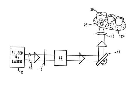
Fig. 1 is a schematic illustration of an apparatus for
applying suitable pulsed ultraviolet radiation on a
tooth, using a series of reflectors and lenses together
with a beam homogenizer to provide pulsed laser radiation
of proper wavelength and energy fluence.
:
Fig. 2 is a schematic illustration of another apparatus
for performing laser dentistry in accordance with the
present invention, where an optical fiber delivery system
is utilized.
Fig. 3 is a plot of energy fluence versus etch depth per
pulse for the ablative photodecomposition of dentin,
using pulsed ultraviolet radiation at 308nm.
Fig. 4 is a plot of energy fluence versus etch depth per
pulse for the ablative photodecomposition of enamel,
using an excimer laser providing an output radiation at
308nm.
Figs. 5 is a plot of energy fluence versus etch depth per
pulse for the removal of carious material using
ultraviolet light pulses at 308nm.
~` Y09-92-120 10
Fig. 6 is a combined plot of energy f]uence versus etch
~7 depth per pulse for the removal of enamel, dentin and
, carious material using uitraviole-t radiation pulses at
l 308nm. The data from Figs. 3-5 are plotted on a common
scale to facilitate comparison of ablative
photodecomposition of enamel, dentin and carious
material.
~.
Figs. 7 and 8 schematically illustrate a dental tool in
accordance with the present invention where a suction
! tube is used to remove particulates and other matter in
i the plume of ablated material from a tooth.
.....
Fig. 9 is a schematic illustration of a laser dental tool
which uses the signature of the type of tooth material
being ablated to automatically adjust the characteristics
of the UV laser ablation pulses.
Fig. 10 is a schematic illustration of a laser dental
tool which can be used to protect the dentist from
contamination by adverse biological products produced in
a patient's mouth during UV laser treatment.
Detailed DescriPtion ~ ~be Ir~f-r~ed ~mbodiments
When human teeth are exposed -to pulsed ultraviolet light
from a laser above a threshold energy fluence, material
will be ablated from the surface of the tooth. Below the
threshold energy fluence, no material is removed. It has
been discovered that healthy enamel, healthy dentin, and
carious lesions each have different energy fluence
thresholds for ablation, as well as different absorption
coefficients which describe the characteristic depths to
which UV radiation is absorbed in the different
materials. This allows the use of a single UV laser
system to accomplish several dental procedures safely, in
which different windows of opera-tion can be defined.
~''' '''
:
:;;
~ ~ Y09-92-120 11 ~ 2
. ~,
. . ,
Figs. 1 and 2 illustrate suitable forms of an apparatus
that can be used to deliver ultraviolet radiation to
, teeth.
', ~
ii In Fig. 1, a pulsed ultravlolet laser 10 provides a light
beam 12 in the wavelength range less than abou-t 400nm.
Rare gas halide excimer lasers can be used as the
radiation source for providing ultraviolet outputs at
193nm (ArF), 248nm (KrF), 308nm (XeCl), and 351nm ~XeF).
Additionally, a solid state laser such as a
bi frequency-tripled Nd:YAG can be used to provide an output
ii at 355nm. In order to be able to block the laser beam 12
on demand, a shutter 13 is provided. A beam homogenizer
14 is optionally provided to ensure that the beam is
~j uniform in intensity. Beam homogenizers are known in the
A'l art, as can be seen by referring to Y. Ozaki and K.
i~ Takamoto, Applied Optics, Vol. 28, p. 106 (1989). In a
particular embodiment, homogenizer 14 can be comprised of
~`~i a series of lenses (Y. Ozaki et al., ibid) or a series of
highly transmitting channels (M. Wagner et al., -
Measurement Science and Technology, Vol. 1, p. 1193
(1990)) that cause the various parts of the beam to
. crisscross and overlap, thereby smoothing out intensity
variations and eliminating hot spots. Since excimer
lasers are multi mode lasers, hot spots may occur. The
homogenizer generally breaks the beam into small beamlets
i which are then recombined to provide a more uniform
intensity across the beam cross section. ~-
'
.( Beam 12 is then directed to a rotatable mirror 16 from
which it is reflected to a lens 18. The lens is chosen
to have a focal length sufficien-t to cause a focused
point of light to be delivered to the tooth 20, and
particularly to a localized area 22 to be irradiated.
Area 22 can be, for example, an area of a lesion, such as
i a carious lesion on the tooth. In Fig. 1, the teeth are
schematically illustrated as is a section of the person's
il gum 24. In practice, the apparatus (even including the
laser 10) can be located in an articulated arm of the
type commonLy used by dentists.
.~ ,
.. . .
Y0~-92-120 12
As an alternative, the rotatable mirror 16 and lens 18
can be replaced by a curved concave mirror. This will
deflect the light beam ancl also focus it. A mirror with
a coating of a highly reflect:ive material, such as Al or
a multilayer dielectric, c~n be used.
Fig. 2 shows another embodiment for an ultraviolet
delivery system to a tooth to be irradiated. Components
having the same function as those shown in Fig. 1 are
given the same reference numeral. Thus, the laser 10 in
Fig. 2 provides output laser pulses 12 of wavelength less
than about 400nm. Shutter 13 is used to block the light
beam 12 as desired by the dentist. A lens 26 is used to
direct and couple the focused laser beam 28 into an
optical fiber 30, which carries the laser pulse. The
laser pulses exit fiber 30 to provide a pulse train 32
which impinges upon tooth 20, and particularly on the
area 22. Due to the multiple total internal reflections
which occur in fiber 30, beam homogenization will
automatically occur to ensure that the output beam 32 is
sufficiently uniform in intensity over its cross section.
The apparatus of Fig. 2 is desirable since the dentist
can hold in his/her hand a tool consisting of the
delivery end of the optical fiber delivery system. The
dentist can then manipulate this tool to direct the laser
beam to the desired place (22) on the tooth. A very
short focal length lens 34 located at the delivery end of
optical fiber 30 enables the dentist to hold the tool
close to the tooth and to provide a very focused beam at
the area 22 to be irradiated. The end of the fiber can
be shaped to provide a lens, or a lens can be attached to
the delivery end of the fiber. Thus, material will be
ablated from the tooth in a very controlled area easily
observed by the dentist.
.~ .
Examples
Quantitative experiments were performed on human dentin,
enamel and carious lesions. Approximately 2mm thick
..
, '~ Y09-92-120 13
,: .
,;j cross sections were cut from the middle third of the
crowns of several molar t.eeth using a Buehler Isomet saw
with a diamond wafering blade. Both surfaces of each
section were polished wi-th 320 followed by 600 grit wet
carbimet polishing paper. Sections were then immersed in
6% citric acid and shaken for 2 minutes to remove the
smear layer. They were then rinsed with deionized water
and s-tored in 70% ethanol. Carefully selected areas of
these cross-sectioned human teeth were exposed to a given
number of pulses of light from a 308nm XeCl exclmer laser
, at a given fluence. Using a machanical profilometer, the
depths of the resulting ablation trenches were measured.
.I The beam energy fluences were then plotted on semi-log
paper as a function of ablation trench depth per pulse,
I and a straight line was fitted to the data. Assuming
i Beer's law correctly describes the absorption of the UV
3 radiation within the tooth, the following expression will.
describe the relationship between the amount of material
removed and the applied energy fluence:
:
where F is the fluence of the laser beam at a depth !'`~
Q into the irradiated tooth,
:.
Fo is the fluence of the UV radiation at the surface
of the region being irradiated, and
: :'
: a is the absorption coefficient for the dental
material being ablated. ~-~
By measuring the depth d per pulse of an ablated hole as
a function of laser fluence, the fluence threshold for
~ ablation Fth and the coefficient a for the ablated
¦ material can be determined:
,:
Fth = EOe ~ ;
The energy p~er unit volume E being deposited at a depth Q
in the irradiated material is the product of the energy
"
'
'' '
-` Y09-92-120 1~ 2~ ~
,
fluence F at that depth ancl the slope ~ of the logarithm
of -the applied fluence versus ~epth plot. Thus
E = F~
When the energy per unit volume E exceeds the threshold
energy per unit volume Eth, ablation will result. Since
-the slope a is a cons-tant for each dental material
(enamel, dentin and carious material),
Eth = Fth~
Plots of data for the ablation of dental materials are
shown in Figs. 3-6. Fig. 3 illustrates the data for
dentin ablation, Fig. 4 illustrates the data for enamel
ablation, and Fig. 5 illustrates the data for ablation of
carious material. Fig. 6 is a plot which combines the
data in Figs. 3-5.
Referring to Fig. 3, for dentin, the ablation threshold
fluence, Fth, is 1.04~0.06 J/cm2 and the absorption
coefficient a is 2.7+0.1~m 1. The energy threshold Eth
is thus 2.8 x 10⁴ J/cm3.
Referring to Fig. 4, for enamel F~h is 5.9+0. 3 J/cm2, a
is 3 . 8+1.5~m , and Eth is 22 x 10 J/cm .
The ablation depth per pulse for dentin is approximately
0.3~m for an incident fluence of 2.3 J/cm , at which
fluence enamel would not be ablated. For enamel, the
ablated depth per pulse is approximately 0.03~m for an
incident fluence of 6.6 J/cm2. From these measurements,
it is apparent that there is a wide window of fluence
where dentin can be ablated without removing or damaging
enamel that is unavoidably exposed to the laser beam.
Experiments were also performed to determine the
threshold energy fluence for the ablation of carious
material. These studies were performed at 308nm using an
excimer laser. A tooth having caries therein was
".
2 ~ ~ 2 ~
YO9-92-120 ]S
preserved with an alcohol solution and then a flat
~ surface was made by polishing with emery paper. This
i facilitated visual inspection before and after
I irradiation to determine the etching effect of the
i ultraviolet laser pulses. Five holes of about 0.3mm2
cross-sectional area were then etched into the carious
material by application of UV laser pulses of different
fluence. The depth per hole was measured using a
mechanical profilometer profilometer, and the resulting
data are plotted in Fig. 5. As noted in Fig. 5, Fth for
carious material was determined to be 1.36 J/cm , while
the slope (a) of the curve is 0.25~m 1 Eth for carious
material is thus 0.34 x 10 J/cm .
The foregoing experiment was then repeated with the same
tooth, after rinsing wlth an alcohol solution and
polishing a different region of the tooth. Five new
holes were etched into the carious material. The same
mask was used as was used in the first experiment, the
holes being about 0.3mm in cross-sectional area. Again,
the depth of each hole was measured and plotted against
the known energy fluences that were applied. The
wavelength of the încident radiation is again 308nm. The
results were essentially identical to those of Fig. 5.
It was initially surprising that the energy threshold for
ablation of dentin is less than that for carious
material. Since carious material is primarily organic in
nature, it was expected that the ablation threshold for
the carious material would be less than that for the
harder dentin material. However, as noted above, it is
the threshold energy per unit volume which must be
exceeded in order to have ablation. Comparing the slope
of the curve in Fig. 5 with that in Eig. 3 indicates that
the curve in Fig. 5 is much flatter than the curve in
Fig. 3 for dentin ablation. Thus, the absorption
coefficient a for carious material is less than that for
dentin, the energy threshold is more -than 8 times smaller
and much more carious material will be removed than
healthy dentin for the same fluence of applied
.i
2~2~
YO9-92-120 16
. 1 .
ultraviole-t energy. The amount of carious material
removed at a given energy fluence can be as high as ten
times that of the amount of dentin removed. Since the
light penetrates deeper into carious material, a higher
threshold fluence is required to produce ablation for
caries, in contrast with the ablation threshold for
dentin, where the light penetrates less. When operating
above the threshold energy for carious material, dentin
will be ablated as well as carious material, but the
amount of dentin that is ablated will be significantly
less than that of the carious material. The data from
Figs. 3-5 are plotted in Fig. 6 on a common scale, to
facilitate comparison. Fig 6 illustrates the different
thresholds and rates of removal of these different types
of tooth material.
In order to provide a safety factor, i.e., not to
excessively ablate healthy dentin when it is desired to
remove carious material, a "signature" is re~uired to
indicate to the dentist the nature of the material being
ablated. Above the threshold fluence for caries, a loud
popping sound will be heard, accompanied by an
orange-colored plume. When all of the carious material
has been removed and healthy dentin is exposed to the
ultraviolet pulses, the popping sound will become softer
because the amount of material being ablated is less.
This provides an indication of the material being
ablated.
One way to view the ablation process is that sufficient
energy per unit volume must be deposited in the material
to turn it into a gas. The ma-terial will expand and blow
out of the etched hole. The energy fluence must be
sufficiently high that the energy per unit volume will
cause this to occur. Whether the mechanism is
characterized as thermal bond breaking or photochemical
bond breaking is not germane to the successful removal of
all types of dental tissue in accordance with this
invention. The term ablative photodecomposition, or
ablation, is used in a generic sense to include both
.~, ,;'"~
.1 .;.
Y09-92-120 17 ;~ 2 ~ ~ ~
..
thermal bond breaklng ancl pho-tochemical bond breaking
where the application of ultraviolet radiation occurs in
a manner to blow away irradlated material at a rate
sufficient that there is minimal thermal diffusion into
the nonirradiated material. It is recognized that, if
the repetition rate of ult.raviolet pulses is too high or
if the pulse width is too great, the ablation products
will not be able to "blow-off" from the irradiated
material fast enough to prevent e~cess thermal diffusion.
In this case, thermal damage of the edges of the
irradiated region could result.
A signature of ablation is an easily discernible popping
sound that is synchronous with the laser pulses. This
sound is heard only when material is ablated, as
confirmed by post-ablation measurements. The sound is
generated by gaseous material ablating off the surface.
Accompanying this sound is an orange-colored "jet"
emanating from the ablated surface. These two signatures
become more pronounced wi-th increasing fluence above
threshold. They are absent below the ablation threshold.
Consequently, this sound and -the orange-colored jet
present a simple and immediate way to determine what sort
of material is being ablated by the laser pulses. For a
given fluence above the -threshold for ablating enamel,
the popping sound and jet size are much more pronounced
when this fluence is directed onto dentin than onto
enamel. Therefore, when ablating enamel at the surface of
a tooth, the popping sound and orange-colored jet will
strengthen dramatically as soon as the ablation trench
has penetrated through the enamel to the underlying
dentin. This provides an in-situ indicator to reduce or
shut off the laser fluence to prevent unwanted
penetration into the dentin. Of course, the dentist c~n
also stop to observe the results of the UV irradiation at
any time during the procedure.
Decayed material, which is predominantly organic, has an
ablation threshold below that: of enamel. Decayed
material was selectively removed from underlying dentin
'
YO9-92-120 ]8
and enamel using an enercJy fluence of 2.3 J/cm2 (308nm),
well below the threshold fluence for ablating enamel.
Additionally, an energy fluence of 2.3 J/cm2 was able to
ablate decayed material more effectively (i.e., at a
significantly greater rate) than dentin, as indicated by
the more pronounced popping sound and orange jet
signatures.
It has been found that organic materials in dentin
tubules can be removed by UV laser radiation at
thresholds less than the ablation threshold for dentin.
The organic material in the tubule ls removed without the
necessity for clogging the tubules. This selective
ablation technique may therefore assist in desensitizi.ng
teeth.
As noted, other UV wavelengths can be used. The
selection of 308nm for the experiments illustrated in
Figs. 3, 4, and 5 was based on the existence of optical
fiber delivery systems for 308nm radiation, these optical
fibers being capable of transmitting sufficient energy
fluence for material ablation. Examples of materials
suitable for optical fibers at this wavelength are the
following: ~uartz, fused silica, and selected sapphires.
Lens material suitable for application with ultraviolet
wavelengths include those fabricated of quartz, calcium
fluoride, magnesium fluoride, fused silica, and UV
sapphire.
, ~ .
This laser system has also been shown to remove stain
from teeth. In almost all cases, staining is a
discoloration of the organic pellicle overlying the
enamel. This material is organic in nature and consists
of salivary proteins which form a deposit of only a few
microns thickness. Instead of removing stain in the
traditional way using an abrasive technique, ultraviolet
pulses can be used. The organic s-tained material has an
ablation threshold below that of normal enamel and can be
easily removed without affectin~ the underlying enamel.
.: ~
Y09-92-120 ~9
:.
.,
Tartar, or calcified plaque, can also be removed by UV
radiation.
Tt may also be possible to use ultraviolet laser
radiation to provide dentin desensitization for those
people who have very sensitive teeth. This
desensitization would be achieved by creating a
sufficient increase in temperature to cause the dentin
tubules to be sealed.
.,
As reported by B.D. Goodman and H.W. Kaufman in the J.
Dental Research, page 1201, October 1977, laser radiation
can be used to enhance fluoride uptake into human tooth
enamel and also reduces enamel dissolution in acid and
therefore its susceptibility to tooth decay. In this
:~i prior work, an argon laser was used at a wavelength of
514.5nm. In a later work, a C02 laser was shown to be
~ even more effective (J. of the Japanese Society of Laser
j Medicine, vol. 6, pp. 231-234, 1986). In the practice of
the present invention, an ultraviolet laser source can be
i used in combination with a fluoride carrier in which the
fluoride (NaF or another fluoride) is dissolved in a
¦ solution that does not char upon laser light exposure.
The fluoride carrier can range from water to compounds
that will dissolve fluoride but not char upon
~ irradiation. The fluoride carrier is preferably an
¦ inorganic carrier which will not char under UV
irradiation, where the carrier is at least about 70%
transparent to UV radiation. This radiation is applied
at an energy fluence less than that which will cause
:1 ~
ablation of the tooth material. Further, the total
`j thickness of the fluoride containing layer is less than ``
i that which would make the transmission of the UV
radiation to the tooth surface less than about 70%. A
suitable thickness is typically less than about 1-2mm.
Fluorapatite production on the tooth surface will be
¦ enhanced without total energy absorption sufficient to
increase the tooth temperature to an amount which would ~`
cause pain or damage.
::
1. .
.. .
Y09-92-120 20 2 ~
It is also possible to provide both ul-traviolet lasers
and lasers which produce infrared radiation or visible
radiation for operation on soft tissue. As an
alternative, a single ]aser which is capable of
generating both infrared and ultraviolet light can be
used. Such a laser may be, for example, a frecluency
multiplied solid state infrared laser such as Md, ~o, or
Er:YAG, or a Ti:sapphire laser, or diode lasers. Since
it is difficult to provide lenses which transmit well in
both the UV and IR wavelength ranges, the alternative
structure, i.e., the use of a curved concave mirror in
place of the plane mirror 16 and lens 18 in Fig. 1, is
preferred when combined UV and IR wavelengths are used.
Interspersed pulses of IR radiation can also be used for
sterilization purposes.
~.
In order to prevent the excess build-up o~ water that is
used for cooling during drilling, it is common to remove
by suction carious material as well as blood, tissue,
saliva, and water spray. Since the dentist's drill may
be subject to contamination, the drill has to be
regularly sterilized. In contrast with this, the
application of laser pulses is a non-contact -technique in
which the ultraviolet radiation itself can be used to
steriliz~ the mouth during dental treatment. The UV
light is reduced in intensity below the ablation
threshold for this purpose. This type of ultraviole-t
treatment can be undertaken before or after the ablation
procedure or, as an alternative, lower power UV pulses
can be interspersed among the ablation pulses to
neutralize the plume that develops during ablation. An
easy way to do this is to use a beam splitter to split
the ablation pulses into two pulses where one of the
pulses is delayed. If desired, the delayed pulse can
also be reduced in intensity. The delayed pulse is used
to minimize or remove the bioactivity of the plume.
; .
The plume consisting of particulates blown off from the
ablation site, includiny any other matter, can ba
evacuated by suction duriny the ultraviolet ablation
`' ~ Y09~92-120 21 ~2~
process. Fig. 7 shows one possible technique for doing
this in which a tool 36 held by the dentist contains both
an optical fiber 38 for delivering the ultraviolet
radiation to the tooth 40, as well as a small tube 42
which acts as the inlet encil ~or a suction mechanism
connected to the vacuum pump 44, and then to a filter
(not shown).
.
As an alternative, the suction tube 42 can be an anular
tube that is coaxial with the optical fiber 38, as shown
in Fig. 8. Both the fiber 38 and the anular suction tube
42 are located in the dental tool 36.
The pulse width and pulse repetition rate of the
ultraviolet laser pulses are chosen so that the dominant
mechanism for removal of material is ablative
photodecomposition in which there is minimal heat
diffusion to surrounding areas of the teeth or gums.
While the ablation threshold must be met or exceeded in
order to have ablative photodecomposition, the upper
limit on the energy fluence of the pulses is that which
would cause excessive heat or damage, i.e., energy beyond
that which is desired for e-tching. Further, the pulse
repetition rate and the width of the optical pulses are
also chosen with these parameters in mind. Excimer
lasers are presently available which provide repetition
rates of about 1-2000 Hz where the typical pulse duration
is about 10 nanoseconds. Pulse broadening to about
50-lOOns can be used to minimize fiber damage. Excess
thermal diffusion (which can cause pain and/or charring)
is prevented if the pulse width is less than about lOOns
for repetition rates less than about 20Hz. For larger
pulse widths and/or higher repetition rates, water
cooling can be used to reduce undesirable thermal
effects.
In addition to the excimer lasers previously described,
nitrogen lasers are available which provide ultraviolet
light at 337nm; however, these lasers are usually of very
low power. hilso, fluorine lasers are available providing
Y09-92-120 22
outputs at 157nm. Various colrlmercial lasers operatiny at
193nm are available haviny pulse repetition rates of 200
pulses per second where the pulse width is about 15
nanoseconds. Corrective lens elements can be used to
provide rounded-square spot s:izes of 0.5mm by 0.5mm, or
less.
'.
¦ Fig. 9 schematically illustrates a laser dental apparatus
which uses a "signature" of -the ablated material (enamel,
dentin, or carious material) in order to automatically
adjust the power output of the laser which produces the
UV pulses for ablation of the tooth material. In this
I manner, the dentist does no-t have to rely only on his/her
3 expertise in determining the type of material which is I
i ablated. This can provide a very sensitive control of
the energy fluence/pulse, pulse repetition rate, etc. of
, the laser output so as to minimize the removal of s
¦ material that is not to be ablated.
I In more detail, a laser 46 (excimer, frequency multiplied ~-
I solid state laser, etc.) provides ultraviolet pulses
¦ which are coupled into a delivery system such as an
optical fiber 48 for delivery to an area 50 of the tooth
1 52. These UV laser pulses will have an energy
i fluence/pulse suff.icient to provide ablation of the tooth
material being irradiated, where the material can be
either enamel, dentin, or carious material. As noted
I previously, ablation of these different materials occurs ;~'
at different energy thresholds, and the ablation produces
different signatures. Both the "popping sound" and the ~;
, ~
orange-colored jet emanating from the ablated surface are
different when the surface being ablated is enamel,
dentin, or carious material. For example, the
orange-colored jet will strengthen and/or change color
when dentin is ablated, in contrast to when enamel is
ablated ~at the same energy fluence). When decayed
material is being ablated, the ablation will occur at a
significantly greater rate than the ablation of dentin,
which in turn will provide a more pronounced popping
sound and a more pronounced orange-colored jet. A sensor
,"
.:
Y09~92-120 23 ~ 1f~
which detects either or both this popping sound and the
orange-colored je-t is used -to provide a control signal to
the laser 46 to control the properties of its output
pulses.
In Fig. 9, a second laser 54 provides output radiation
pulses which pass through dichroic mirror 56 and enter
optical fiber 58 for delivery to the region of the plume
emanating from the ablated area 50. Depending upon the
material being ablated, different strengths of the orange
color will appear, providing different wavelengths and/or
intensities back into fiber 58. This return signal
reflects from mirror 56 to a detector/analyzer 60.
Depending upon the color signatura of the plume, a signal
is provided to the laser O~ltpUt control unit 62. Control ~-
unit 62 provides a signal to laser 45 in order to adjust
its output power, repeti-tion rate, etc. in accordance
wit~ the type of material to be ablated. ~ -
': '"
The output pulses from laser 54 can be delayed with ~`
respect to the pulses from laser 46, by using a delay i~
unit 64 between the control unit 62 and the laser 54. In .
this manner, the output from ablation laser 46 can be
quickly adjusted as soon as the detector/analyzer 60
notices that a different material is being ablated from
region 50 of the tooth 52. Delay unit 64 can be omitted ;~
if the system is designed to use the first few ablation
pulses for analysis of -the material being ablated. After
analysis, the control unit 62 would adjust laser 46 to
set the proper energy of the UV laser pulses. .:
To provide control using the signature popping sound, a
small acoustic sensor 49, or fiber optic pressure sensor
or fiber optic microphone is located at the end of fiber
58, to allow it to be close to tooth 52. Sensor 49 is a
transducer which provides an electrical signal that is ~-
sent to the analyzer 60 along line 51. The rest of the
feedback control is the same as that described
hereinabove. ~
~: .
; -~ Yo9-92-120 2~ ~t~2$~
;
Fig. 10 schematically ill~lstrates a laser dental
apparatus which can be used to protect against the
I occurrence of bioloyical contamination, such as
hepatitis, HIV, etc. In this appara-tus, a fiber optic
'''! biosensor is used to provide recognition of biological
conditions in the patient's mouth. For example, if the
fiber optic sensor de-tects the presence of a selected
virus in the material being ablated from the tooth, a
feedback signal can automatically stop the ablation
laser, or trigger the ablation laser to operate at a
lower power in order to provide a germicidal effect in
which the unwanted virus is destroyed or minimized, while
~s not causing further ablation of the tooth (and therefore
3 stopping the production of additional airborne biological
contaminants). This contrasts with the problem of
aspirating contaminated material from patients when
conventional mechanical drills are used.
" ~,.
In Fig. 10, a laser 66 provides UV output pulses that are
coupled into optical fiber 68 for delivery to a region 70
, of the tooth 72 to be irradiated. Another optical fiber
74 transmits a response from the area of the irradiated
section 70 to a detector 76. The output of the detector
is sent to an analyzer 78 which determines what, if any,
l harmful biological material is present in the plume
¦ emanating from the irradiated region 70 when it is
ablated. The analyzer 78 then provides a signal to the
laser control unit 80, which in turn provides a signal to
l~ laser 66 in order to either turn off laser 66, or to
', reduce the energy/pulse of the UV pulses from this laser,
or in some other way to alert the operator (for example,
an alarm or indicator light).
.'
A layer 82 of a biologically sensitive recognition
¦ element (such as an antibody, DNA or a chemical) is
located at the distal ends of fibers 68 and 74.
~ Dependent on the signal received from the area of the
i irradiated region 70, layer 82 provides a biosensor
function, i.e., it recognizes biological material in the
vicinity of the irradiated region. This material causes
J ~ Yo9-92-12~ 25
~ .
a change in the light reflected -to the detector along
fiber 74. Different -types of fiber optic sensors,
including biological recognition elements, are described
in an article by David R. Walt, appearing in the
Proceedings of the IEEE, Volume 60, No. 6, June 1992, at
page 903. The indicating layer 82 modulates light sent
down the fiber from the laser 66. The amount of
modulation of the return light from the area surrounding
the irradiated region 70 can be a measure of -the amount
(including presence/absence) of a particular material in
contact with the fiber tip.
The sensor layer 82 can be used to provide an indication
of temperature and/or pressure if it is desired to
control the amount of heat build-up due to the rate of
ablation from the tooth 72. In operation, if the
temperature or pressure goes above a preselected amount,
this would trigger a feedback signal to reduce the
repetition rate of the laser pulses and/or the
energy/pulse. Further, the fiber 74 can be used to couple
radiation of different wavelengths back to the detector
76. The wavelength being detected will depend on how the
system is designed, i.e., what type of signature the
system is attempting to locate and detect.
While separate fibers 68 and 74 have been illustrated, it
will be appreciated that a single fiber or fiber bundles
can be used. Also, a bifurcated fiber can be used in
which the fiber is split so that the excitation radiation
is transmitted through one portion while the return
signal is collected through another portion.
The detector 76 is designed to be sensitive to the
signature of the species being detected. It can be
chosen to be responsive -to wavelength, intensity, etc.
Suitable detectors inc].ude various diodes and diode
arrays, charge coupled devices, photomultiplier tubes,
etc.
-~ Y09-92-120 26 2 ~
. .
, .
US 5,107,516 describes a spectroscopic feedback system
utilizing two lasers whereiZl resonance fluorescence
radiation is used to provide a feedbach signal to control
the ablation laser. In the system of that patent, the
distinction to be detected is that between arterial
pla~ue and normal tissue. Additional references generally
describing feedback systems for use with lasers in
medical applications and dentistry include D.R. Wyman et
al., Proceedings of the IEEE, Vol. 80, No. 6, p. 890,
June 1992 and German paten-t DE 40 15066 Al. In contrast
with these references, the presen-t invention uses the
signatures of sound and/or color jet and/or tissue
temperature described herein to control the ablation
laser output used for the treatment of dental tissues.
While the invention has been described with respect to
particular embodiments, it will be appreciated by those
of skill in the art that variations can be made without
departing from the spirit of the present invention. It
has been taught that there are ablation threshold windows
allowing the use of ultraviolet light to do selective
hard tissue and soft tissue dental procedures, a feature
which has not heretofore been available to dentists.
Depending upon the ultraviolet wavelength chosen,
slightly different ablation thresholds will exist for the
various types of tooth material including enamel, dentin,
and carious decay. However, regardless of the wavelength
chosen, these ablation thresholds can be determined by
the procedures described herein and illustrated with
respect to the plots of Figs. 3-6.
The windows of opera-tion described herein make it
possible to selectively do other procedures safely, as
for example curing resins for bonding to tooth
structures, sterilizing root canals and other surfaces
and rem~virg tartar from to~th surfaces.
'
;