Note: Descriptions are shown in the official language in which they were submitted.
The invention relates to a hot rolled metal beam, and a
method of manufacturing such a beam, and in particular to
such a hot rolled beam having flanges and a web joining the
flanges and wherein the flanges have a predetermined first
thickness and wherein the web has a predetermined second
thickness less than said flange thickness, and wherein said
web has openings formed therein, and to a forging die for
forging both portions of such a beam, or for cold forging
other metal members.
x'103002 .
,.
,..
numeroc.is such beams are used for example in :a building, i.t
will reduce the overall weight of the building, and may thus
enable the use of footings having a lower weight bearing
saecifications.
It is also possible by this technique, to produce beams
which have a equal or even greater load bearing capar_ity in
themselves, than equivalent beams of solid rnet.al.
In particular, the so called "castellated" beam shows
many of these advantages. This beam typically is former! of a
solid I-section hot rolled beam. The I-section is then cut
along the middle of the web, usually into a more or less
zig-zag pattern. The two halves of the beam are 'then
rewelded together with the peaks of the zig-zag portions in
contact, with one another. The zig-zags thus form openings
between the joined peaks. An example is shGwn in U.S. 'x,;,
Patent 4,8~a4,898, Inverter P.A. Walker,
The.resultant fabricated castellated heam is
consid9rab.ly deeper through the web, than the original beam,
but the flange portions of the beam remain unchanged.
ZO Such a beam will have increased load bearing capacity
' ' n ~ ' ,~ .; , ,
as comparc~rJ with the original ;solid I-beam section, without
containing any additional metal, and thus, without any
increases in weight, as compared with a solid I-beam.
Castellated beams also have the advantage that by
pr'ov'iding openings through the web of the beam, it becomes
.j. ~..,...
r:; : f
>'. . ~. ,...I:' 7 ; :
i !:.i
~ ! ':Y
I. : .~'i.n.
I
, . I.
':1~..~
"a
.x.... ..
r
,:::
.1
".
.::~l
t
.I ,.
.~u~! ra
,
n.. ..
~
~ ~~, ;i ,, ~,'~ : ..:: .~ w ~. .,: ...,i-'' ~,. :.,.. ~,~.~ ::,':
n ..:
. i.
..,,;,. , .,. ~ ..;~. ':' :..,~: ::~.. . ..s:. ..::;: ..';. . ~ : .: . w
:~.:.: , ~ .~r;.. ,.,:,~ ; ,..., . . , , ". .,. .: ,
v,.,. .,... .:::~..... :v. ~.;. .:..;r~.. :...,.. ...~.,.::, :. ,.r.
.,..:,:....~.,:.:,: .. ::.~.~ ..~,.; ,.... .:::-, ~t~ , .... ". ,..... . :..,.
L:.:.
n'' ~' ::.:; ~:.::; .'::' ' :~': :- ,:...~':, ~.~:n~.. , , .. ; ;;.;;,.. . ' ~
:n..:.. ,:: ,.;: ....
~::...;~.,1 ,,,.... . ,:.'~ , '..:... .,
i;
n
.:
..
, .~
n e
s ;~i
I ..,
.. . L . , ':'~: r
r
a...Y t
n f
.. r.::~ .,.~,:..:
n .'. ~,. ., 1
(.-".: I
a.:l ....
. ,n .,..
;, ..:... ~,., . ~.:%:n, ~~:; . :.,~:' .:.:., n: a;...~.:.. .. ,..~...~.....-.
., ., ~:'I'..,.:.. ., ..,. ':, .~,.. ..,.. ..,.... ,:: n ~.. "'" ,:.': ::
.,...,.. ;....:.,.,,. :'.~, ~;:.:l::, ~-- .::~ , ~ :,:~.:; n .,. . ,," .
.fir.:: . , ...,....,: . ", :..
. ; .,.. ....... ~,:. :':: ~ .., n.:.::,.,:.:. ~. .. ~;: ~~..:~ ..,,.., .'.:.:-
: ~:.~' ~~ ~ . :...~:
i ~.,-,~..~~, ..,.... . .:..~:.. .'.,.n..~::.;.....:. ..,~.,.~.. '~..:;.
.......,.,. : .. .: ~:.y. ......,_.. .,.,......,.... :~:. ~. ~...,, ,,
,.,~....; , ... ........" . ~ ~~.....
.r ...,.,...., ... .. . ~.....: ~ ,....,. :.,::. .. : . ~.",, . .
~,~:........." ... . , .:..,...: . ....,. .:: . .: ... , ..... ,.,:..: ..
~,.,..., ..... .,.: . ,.: . . . . .
1 ~''" :'.-..:. ..i., ,:.~..:: 1 .:'w..: .......'::, ;,.'.~ ....,:,. ,~,..:.,
:.~:,'.. ~ ..:......~~ .. .~:.:, ~~:~::.: '~ .,. ....:: ~.;..,:...~ ,:~:.
., i., ::
.... .,W~...,;.:'.. ~:!::.;. . .:: ;:~::; ,.. ..,.:,.,:...;....,..,... S
'~::ii, :~;~'" ...'.'., ..,,:'' :.,:-: ... ..'::.~~ . '.~!...,...:'..
. ~'.~~,: ~..~,'.~ , ~ '. : i:. . ~,.'.. .:, ,~., ,.. e:..:.~.. ~. ::. :.
.~..~,'. . : : i :" . .:..~. , '~: ..: , ..~, , '~. ,'_,
.,..,; ;::~ ,,......,, ..:::.: ~. ~".:., :.~ ....:~:'~.. . :~::: . :,I ~:!.
..:,:,,:~ . ,.~:~:~ , ~,;.~.: ' ,.
l s
r
r
,,,;'; :,... ,.: . ~ . ~ :, . ::. ,. ,::: : ?: . : ;'..' . .. : :, ; .~. .
d, .~ ~,;
I .,. '
.h
' ',.:., ..:,.~,: .....,~ : , ... '. ' , ',.:, ~ .,: ..;y.. . , ,.'.~ -:...
:.:, ...:..". , :: ..,.w .::,~, :.,~ . '. '.n.
lu '
.1:
i ..
1 .,.
1.
i
F
f , :~::!~ ~ .:~, .: .,' '.~: .. ~' .., ',~.', . ~,;' ,'... '.!. . ..: ~ . ~ ~
v , ,~~.~:,! :~ y..,: . ' ,::, , , . '. , ,. . : .
v
..:,:.: ~. ; .., :.. ...: ; :.:..; ~.; ,. . ~;:.:. .::.~: ... ,:.. :.:. ,...:
'.; . ~ r ~:.;. ~ ., '.~.~ ::~:-~ . ''.~, :,:.:: ,... ~ ...:.
1":.:,: ..: ~; .. .!~.:,. ..,.I..' :.'.:-:~~ .:... -"!....:....:.:..,:.
..:.~:.m ~ ...,.;. ...,..,..,.;.:~:: ~..,~,..,.:: .,:.;..... ".:~..,. :...;~;:
I~ ~,:';,:~...,, .,;,. ~ ....::. ,. '~.. .. ,. .~.. ~ ~ '.: .~..i:,..:..:;: .'
" .,;.~ , '~::'. . :'~::: . .;::_ :..,.;.. ....... ....,:
r, . :~ .: ~, ,.:.. . . ~ .,::; . . ..;. ::. , ;~,' . ; ,. . ' ." : , ~ ;;~:
:,~..., :. . v ~ :..: "... ::: ,''.: , . ';:.:~ , .. ;:
,.. :...... .,;:r; .,:,~ ~:.:,- . ... .' . ": . , ::-... ,., . . ,
c.:. .,:: ..: .:'" :., . ,: ....: .: ~: -::>: . :: ~: ., . ::': .. _..'~;~,
,.., . :-'. ,. ,:'..::.,.., .::>., .~:;: ~. ,' .':~ ~:'r:r : - : :. , v ;' .
~~~~~'~~
possible to pass services through the beam. Clearly rhia i.s .
not possibly using a conventional beam with a solid web.
To take a typical exampla, a 400mm solid web beam, when
the web is cut and rewelded so as to form a castellated beam
becomes on an average, a beam having a nominal depth of 550
to SSOmm. Similar advantages are obtained using r.00mm beams
and 800mm beams, and even 1000mm beams, all of these f.i~~ure;-,
being nominal depth figures for the depth of the beam,
It is however clearly desirable that if a method could
be developed for making a beam, with openings pierced
through the web, but without the expensive and time
consuming cutting and welding operation and also without the
need for trimming the ends of the beam, substantial
economies will result.
Such improved beams would have significant savings in
metal and therefore in weight, and, provided no loss in
performance is experienced as compared with a solid web beam
of comparative dimensions, substantial advantages would be
produced.
Another factor in the hot rolling of beams, is that the
flanges and webs are usually of certain standard
thicknesses. Usually the web is somewhat thinner than the
flanges, since stress studies have shown that most of the
load on a beam is carried by the flanges, and that the web
carries a smaller proportion of the load. There are however
practical limitations to the degree to which the web
thickness can be reduced compared with the flange thickness.
Any attempt for example when hot rolling an I-beam, to
form a web which is subtantially thinner than the thickness
of the flanges, results in web distortion as the beam cools
due to residual stresses. If this problem of distortion
could be overcome, the thickness of the web could be reduced
considerably and the beam would still provide adequate
strength in many cases.
zs~3~~2
However the web distortion problem has restricted the
possibilities of varying the design of such beams to provide
adequate performance while saving weight in the web.
Clearly, if a beam can be rolled, with flanges of
standard thickness and with a web which is substantially
thinner than the standard web thickness, of a conventional
beam, while overcoming web the distortion problem,
significant reductions in the cost of such beams could be .,
obtained without a corresponding penalty of loss of
14 capacity.
Such weight savings would save on material costs, arid
:,
shipping costs, and, in construction, would permit more
floors to be built, or the specification of the footings to
be reduced, to name only a few of the advantages.
It will be appreciated that in the foregoing general
remarks, while references have been made to ca~tellated
beams, it will be appreciated that the demand for
castellatc~d beams is only a very small fracaion of the
demand for hot rolled beams. The advantages described above,
,
t.,:
20 when sucfo improved beams are compared with conventional
' ' ' ~ It ~ ~ p.;.i...l : :. . ' . : ~ ~ r
I
(
whi ch represent by far the largest
beams,
portion of the
market, are very considerable, and represent a major ,;;,fr
;;
' breakthrough in the manufacture of such beams.
BRIEF SUMMARY OF THE INVENTION
With a view to achieving the foregoing objectives the
invention comprises a method of manufacturing a hot rolled
.."
r .::;,
t::.-,
:.
.
. .7 .,
... j..
f t :
St
t
.. .
.
.... ...
\!. .
. .., f
"i
.::.
. 7.1
F :.7:1 1
17
..L. . n ..t.
v.:.la .:
r.,t
l..
i..... .
.i. .~
L :
. 7 .: .
.f'::
C
t'a ... .. t
y r
.
S
aJ . ..
:.( 7.
:, , .y' .. I .:': .
1_ ..
..f..., f,.:I . 1n
y ~n
t .. t ..
:1::'~.'
1 . 71 .,
1 , t
, F. '1
:
-~
.,..
f ... .A o . .. ~:
.~ ..: '.:
_ :.i: .. m'_ ' ~ . ~ ~
'...: : , ... . ..:.~: .7 ..'~'.' . -:': ,..~:
f -'
I .' ..L~.a ..:~J.~ :u. ::
:,.t:. '
C' .I. .'.
1. . 1 t . ..
NF.'.' >. ::~
~ i
..n~.:
:
~
~
n
.
n
,7.
..:.,a, ,
:.x..
,.; l:
., t . , :L,,. t...'
:, n.. t
1..
x ,
t .
v, < a.
. '.5..
t, n
. s .1
y ...
.. of . ~ his'. It.l.:~-.,:~..n:.
K ~. , l, : . . t
W ...:1: .. ,
n ~ r,
f?: 1
..n l.. . _ in. ! . ~.
! ~ . .~,
:..
....L' 1. ~ ~v
..I..
.,.
il
T
,
..
.....
.
1. .1
r :
1
. S,.r..:.
1
.,.i .
v
a ,
t ; : i.
o .. : i .r. ~~f:
u-;:
r
.
7 ,: 5....
t
... > . a.
1.t1
I.
7
r 1
:.. 7.'n , 7 .
t.:.
~.:.A ...
7 .:.. i . t
...I
::h '
: t.
lr...
K . :,5, >
t
,:,r . 1
d. , s
.x. t . .F....
f?'...,: ,
\.'; : f ~.( i i.....
. .t
'
i~
~
;
. ,
.
,
...
....n. ~..
.r :
~., t
>..
r r
:.n.'
.,.. I
.Y
Iw':' .~' r.5: . L.
1. ,
. i. :" 7 ~.. - v
r, , t r
n :
n
.
v
.
.
r
I ,t:::
!
~.rn..
1, . .
.,t, ,) , . ..
1. .t
.H . .
1 .i:,.
..:'I.r.". :~I..:,:: i., . .~,..
v I 1 . 1 . ..
~t u,..~ ..
.:,n.'. n..:
1 ..
n,.,..1 .. n .:
i :: S
1, , t '
:. 1
.~:::.. :
. ., i.:.
'~
tt :!
:'
.
-:-'
1 -
: ':
: '::
::':
: :
::
' '
"
C
~~ -
. :.
.. .
,,. .
.
. ..
. .....
.
. -...:,
....
;: ..
.: ,. .I..: ..
.
.,. ,.
,
,. d.
lr...: ..u
5....
' ..r...,t.~
.W I
n
:I..,',; .q ..
Ix {( .: a .
t :
. .1,. . .. N. , n ;.a
i:II
.1. it
m -"L...~
i
n
.s
'
5
.
.
.:...
.
.:.a r. " :
. t
.A!'. ..:
':l:y.:, ....
" fl.,..
..1 -
I..
1
1.,
.l:IY ~~V.. .
. r. .
r...
.. t .
'. 1
I'
fs
~V!
..
.
:,
.
.
s
(?,:
n
m
r.
,,.
f ;
i.:
. ~. , ~
'
~:u
: , ., ..
k , r.
:u
':
~
.
" ...y . . .. ;
, ;
.: .
t. .:,.
, .. :.. , .. ,
, ..: , '~:
...., r. ,.. :
t 1,.... , y
.,x
x:: ... -
I
r :
'.' ~,'
.a
'
~.. .:~:
..
. a
I r
..~- ~~.W
~_ .: ' ..
r
Y
t
"
~
'
.
'
.
~~'
~
.. . ...
. .., ,.
, ',
, "
.
.
. ;::...
. ~.. ..;.::
:
:
, .
:. .I..
..
; .
,
t. .. ,...'.... ... ~." .: . . .. ;
,........, . .... .: ... . . , ..,., n: .,..: ...:
.. ... ....
" .w. . ...-! ~_
:
d t , h ..
..1,...1 :-t ...~... ........- ':.~..:: .:;...:... ~..-".":. ~~ .:
..:...,. :......; ,........... ,._ ....,:: ..... ;....,'...,i.'::........
. .:......., , :: , .;.. ::'" . ".:.:.. :.:.... ~ ::: .'::.: ~ ,.,..;,.,..
:.~:,..:;~ .,..: ~: ..'.::: ..::.,.. :::: :~.
F[? n. w
2~.~3~~2
bearn, said beam having flanges of a predetermined first
thickness, and a web extending between said flanges, said
beam being initially rolled in a hot rolling mill to provide
a beam member having continuous flanges, and a web joining
the same, and said flanges having a predetermined first
thickness, and said web having a predetermined second
thickness less than said first thickness, and said beam
member having been then cooled, and comprising the steps of,
reheating said beam memb~:r to a temperature in the range of
between about 500~"c and 1200''c, passing said heated beam
member through a metal forming press, repeatedly operating
said press to form a series of spaced apart openings through
said web and said press simultaneously hot forming the
remainder of said web to rernove distortion, and thereafter
,~ ~ ~:.
allowing said beam member to cool.
A further advantageous feature of the invention is the
forming of lips around said openings, said lips being formed
at an angle to the plane of said web.
A further advantageous feature of the invention is
focusing the heat required for reheating the beam, so as to
i I
reheat (only the web to a"high temperature, while leaving ,
;! ,.
said flanges at a lower temperature.
A further advantageous feature of the invention is the
forming of indentations in said web adjacent to said
openings.
. ' ~ _6_ _...,:..
.,.,. , ,
> :;
a,
Yy
~ :".
. ,
1
t ..
r.
.r.
a
t . . 1.....
r
.r)..:
r 1 .
r
., 'i ...
....7 :'-.. ...~r:..~
r
.
j':
.n. 7, 'i
~it ..
= . 7. .:: ,:. ~; :..:: . ; '' ; ::; ;.:
. .. .
H ;
's
J
7 ,f ,.;
!.
:!
t
I
.i. a f
A. ~,
t:.1.. ..,,~:.
~ ;:i
i', i
. u1Y
~,
1 . .I .:,. ~..
. r ~::
,:.a':
:;, . c ~: . .< . .a ..
LI .. ~ . . I y .,
1.:. ,
,t 7 t r..
t
,..r . t .., ).l ~:.
.I .I
I:
.r
.. I ~. '.
., I . . .l , . ~c.,l
4
i.,.a. ,.. t....
...x::: :.
..i.
,;
..S :..
': J..
..1.
1
5
.:''.J r',~ ~.
..rt ,
1: .
n..
:. l
rv .~
v .
,;::J~ , i ;T ::.u....
.t.>,
..c
n .: t a
s
t
. r::.
;;7.
r ,
. ,! :.
..u
.t
. ..t'...' 7.u...
r . , 1
.al:
. a . w.. v ..
.i..: n
,
tP ; '
t , . I .,..'
7.
,
r
~: 9
I ,
~r ,, . :.,:;'.
'n
n.
i Y .
,.. V. . . Iv.~..::
i
,!,I , 1
'.;.H ~.,tl..
.::II~
~ t r y, . .
:~ ( ,
'i
..c..: ," n.....
r ; . t
~: ,, ., , i , r.. . , ..
I . ,
~~:!'.o. ., 'V I
I .,
...>, t . ,.: r "t.7.... ) . .
1 r
n7
i ,
n. 7. ., f - ~ .7 .
1 , r
f
1 ,n
i ,;.t:. 11..
7 n .. .n,.r..s.~ : 1
I
;. ~;. ,,. ,7
s :.
: -~S ~ '. rs s . I ~ .
r.
r
I .
, ~,~. .~rl
,S
s r' ,
I ..,.
n;~m,
f. N'.I :i ,7 ..
h. , ;'..,
t,..t, . ,
:.1 . , Y. K:. ''
>. ,.' ;~ k: r
r . , ..., .
i, r ., ..,.. .
:n
G m
'rT' ~I, a 1 ..
'.: n .. . '::
1 ,
z
1,
Z .~a..
...r.:~
r . r
1.,:::
S .
t,
. >!. ..r .. -
~. 5 ' r.
ni
. , .: ;..7 s ... i , .
.7.
r.... ';
r . .f >
. . t. 7 a
. ,.: I
...5:, '; > ..
a 1.:.
. ) :.
:..11.
a. 7 . I '
p
...1..
I a 77: 7
:,.W
. 7.
7..:::~
., r: ,.
t .
1
! .:.
.,)r'
:i:,
. ..>r
.rt.,
~~.'.i .r. .
.~.i.. .: . ,)i:: .
7 ~ ..Y:.~.
.. i . . . i. n ,.;
4....,':
I ':
k
,. E: .
.1
..:"J" .. : . ~t , ... . :. ....... ,., . . ... .: . , ... ~_.....r .._..:.
... . . ... .. ,, , . .~ ., . :i. . .. .., 7.., ." .. . . . , t ..,.: . .,.
21~3~~2 ~ '
A further advantageous feature of the invention .is the
forming of the portions of discarded portions of said web,
prior to or during removal from the web, to provide a
secondary product, after which the remainder of said
discarded portions of said web are removed to Form said
openings as aforesaid.
' ,-.
A further advantageous featuro of the invention is to .,::.,
hot forge the lips formed around said openings, whereby to
increase their thickness, and also, in same cases to'
increase the angle of said lips relative to the plane of
said web .
It will usually be advantageous to subject the beam to
a known straightening operation after cooling, to straighten
the flanges.
I d :
The invention also provides a forging die and method of s
,
s ,,
forging, in which a metal workpiece can be pierced, bent and
forged all in a single die operation. ,
.
It will be appreciated that the beam may be of various '~%
~ K
J ;.,'
different shapes. Typical shapes include an I-section baam, w'
.:;
~ : ari ,H,-,S,e;~tion, :a,;C-sect,io~n" to name. only a .few ~~ '';
typical beam
sections.
The various features of novelty which characterize the
invention are pointed out with more particularity in the
y:
r:
. . ,..
claims annexed to and forming a part of this disclosure.
For a better understanding of the invention, its operating
advantages and specific objects attained by its use,
7.:';J:
~7V !t .,:
F..na:
7 E.: ::
..1:.. ;,.
.1.. ...
.... tn. n ,
-V..n.
':' J J '. , f .
P
..t '.:
.1 f G- . I. . ..1, ...
t'.
t .,7.
. ..i...; .,
.;1
I
-%'
.::1.' V .
1
'YC 'r'
n
~
'
l
5
~
.
..
..
y
J...a ..
.
n: r . f , a
I.
..t.
ni . I , t v..
.. t... . .:b ,. .,.
1: . r
.:: 1.: .I s, ,.
.~ 1. . .../.
. r. a . ~ ,. '
.f : n ,I 1 r,. .I.~.~.'..
D , , ,.
i a
..,l. rl~. ,s.nl~...
1. .. ,i:
., r
r...r . :I .:
.a:4
:.I7. .
:1:'Y'.~,: :'
-:li,.
n ....I .: h.......a. ..
.
1.'. , t ~
i:..;q.. I " t'
I ~~ ... 1 .
,f:.,
t.
.:r
,r
:~
.
>~
.
,
.
.
..
..
.
.:.I.(
a r . ,
/. ...I .
, ,
. . . :.,>.
.i
r.r :.:
.r I.
.
AK,..
L. y :~.
..., f
1.. : i :
..r,. .
1,
:., r. ...
t
r r
1 .
i:
: L. ..., , n r :
n/
1 a
S
r ..
ft
r . v :(
n., r
!
1
..
.
4
.., n
F
a
e.
..i
r..
~.n.; : r.
.I .:
t
1 .
a a : .
.l .'. nJ
c
. 1 f; .r.':
...,r
.z! " .:.,hi I,.~t..
r . i..
.,.W ,I. f , 4!.i~..
n ). 'i ' '.~'. Wr.:~5,. i.:
../ il. ..t.. .L':.
t. . .~..... C ..Iw .,.4 7
1 :..,
a. '
/ .i
SI . ,: :.. f .
~r
;:J
..! , :'~
r
'
:
~
~
l
~ ~
n
~
...
.
..
,
. :
, .
::
:r
,r,. .
. .:.
. :.
f
:i ' ... 7.1.... .
:,~.:. .
1
, a .
S . ..J . . .1:. .
t. t~.. . : :f:
1.;
1.
..':.7.
J.
..1 .::
Y.:
a . n.:~: , ~ r:. r ..
i
.:n.l..
I :.
x
r :-
a
a
_
,:,
.
r ..
.I. :..
.:
.::
i
.,.. t
r n J>:
:. n . ,
:.. I
~ '
., v
n.. . o .. , i.,
p'.a.... .,~~ ..n.:.:',.
.t. .
. .1 ,
.a,. ,
L.... ~.: yr
.1
v
:
1 ..
.;
h:
u. 7
.J;: .
a tt. I r ,
n
I, ;
,1 ,'
r
I.
~
.1 .
rf I
, ..
r.,.
:.';f
n :
:r
::I:.
I
:: t ; .. .. '. '., ~. ?~ . ' : ... . .... ... .. ...~ . . ....
.. :
w a I
.;. ..:..~..:..:,.. . '....... :.."..~,. ,.... , -.:. ' : ...~ '.....",,..:
,.'...J."
.. ,..,..;..: . . ,:.:::... .
rt / ,.
r
is
1
:.. , .;. .. :: ... . , ~ , . .. ;:. ~;. ':
i
.. . . ,.. : .... ::. .. . ....... .7... . : ." . . .,.. . , .
... ,... .:::. .. : :. , 1 ." . .. .. .. ..
~~~3~J~2
reference should be had to the accompanying drawings and .
descriptive matter in which there are illustrated and
k" .
described preferr;ad embodiments of the invention.
IN THE DRAWINGS
Figure 1 is .a schematic block diagram of a facility for
producing beams in accordance with the invention
Figure 2 is a schematic step diagram showing the
sequence of operations for converting the metal member into
a beam in accorr,~anca with the inv.~ntion;
:l0 Figure 3 is an end view of one embodiment of a beam
manufactured in accordance with a first step of the
,_.
invention;
;._.
Figure 4 is a schematic stepwise illustration showing
the steps .in the forming of an opening in the web of the
beam
Figures 5 is a Section along line 5-5 of the beam
illustrated in Figure 4;
Figure 5a illustrates a beam similar to Figure 5 with
openings but without lips
20 Figure 6a and 6b are schematic stepwise illustration
n, ; I .. i ~ ; , , , I
;'
illustrating a sequence of .steps of 'Forming an added value
product, followed by an opening, in the web of the beam
Figur~ ? is a schematic perspective illustration
showing the equipment for heating the web of the beam,
without heating the flanges
< :,
Figure 8 is a section along the lines 8-8 of Figure 7;
~r'" :,;:.o.; ~:r
n . r I
~r,::.a a .
~:.i
1,,
.,,.''~-~.
I
~',
t. 1
a v r
m . , a,
. 1..., . I:,.' , . 1
J.:. t.: - ,
y
,,n: ,. .r...
r .
.1
f..:n:". t , , , :.
f.::.
n
L,.,. ~t ,. . n r
.'
. ,t r,
:...o , ;, .
1 <.
x... a,. .
,'..4: , ,:-''. ,
r
...~c . ..
:,I
.n .:..
.x
S ' ~f
t
7:,.:r .., r ~
,..i! a
~1.. .,
.. r . ". ,
a:i:
. 7
u'.. e,
n. ~..
~3 .:
n,
f .. ;L',
.,.f ,
,,
1 .;
.1 .
..
r :..
:1
t
rC,,;i
,.
1 r ,,.
r, . J .
r . ..;~ ; r.
.L..'.
a:
,'a ,.,. , .
. ~ .:. 1 T .i ..
'~j~', ~... ..,1 . ., t .,
,... j ~.,: .L...
n'~.n,. .
. .. !a , v I i.
.<..n ,a ...1....
.. s
..., n' ~ a .. , ~r. .. I. ;.
,
I.
f
a . .f.. I..'.
..,r. i
e,
. ..., '... , ~., . , ..,i...'.
r,
. 1.. "
::,: ,
n.
r ..n:
.,.i.~
,.f
:,.i':
,...r . -'
rr., ; ::.. ., . .. . . .1 .::. . .. ..: .:: .....: : . . :'. . . -.:; . :
.:'. . , : 'r.;.
.. 1 . , J .:in
. .. ., ... . . .,.7 . . . .., ~ . .. .. ..
e. 1
i.
i
::ø~~:.
S.'
, i,'. ,:7-~ . > :.I
;..:r ,7 ;::4
7....."~
~. n",
t
c
:.
S..~.I:..
! ,.
r.
s.
.d
...~ n
'~.r5.. .. u.'.::,
. r. w' .::y.
I.
r
L~t. ;~
" s ,.. ~ r 1'
~ J , , r.:.:.:
1
1 x
n ...
v
u.~.~ ,
.7. :: . ,i.~
.t.7 ':
t n i,,,
t,: ,.
.i
' :l .
:,: , :v
1
r~ .
1
.1 ..
1
. .,
,r.,..
..., f .
n . ~ri, x ,
,.
Wu''. :~.ii
.c
.. i ..:
;.!:'j.~~ , .,.1 .~.>t:n
'. P
. ..1 .7..,
-.: r ...e
n.
..n
' 5... ~~. ,1 . I. l,
1,
.. 7 1
I : .
J . . "(.:
.;' ll. '
f I..
.1 ,~, . ~ . : I
'. f... . .I .:,1....
1.1 ' ,l ~Li:::~~
11 . '.
., a 1 ';
.(".
.: i I
,. r ~n
/ .i . .~ ~.,...
n.'
~ t .,~:
...:>~ n.
,... n ,
:~,: n . 7. .,
u.1~ ,y
a
7
"(.. :'.(:
11.
V ,, i. '..; 7 ..
.m.u, .., '..":.::
.m, n .....t .....
!
i:.l 7 .w~.
..! ..,.:
.I ..: ',wl. ! ...
~~: 1
f .77 .
S ;i.o:7
. .1 n:
':.r. .: o .,
.7 . ~' : , :. t . t. ...
G as
G:~.
A:...~., ...,. : . t.
t. .
.I..:.'.' ~I., S
' .1.. I 1,.~,.A .1. z
i:~~ '
,t.y.u. .aI'..,
H .>
5. .J u'. , .f .,
, 17, 4
.. .l 7 . s : ,.: A . . 4....,:
'.1-. i
1
.I - 1
..7 I 1.,...
i:... .. 1.,.~.
~. . a : f.. w . 1 .
.r
d,.n W i,.::
f S :'. !
.J f. , fly':.
.( ,
1. t. 1 ~ . ..',S I 1
!.. . i .....f.. :.
..,X 7.
~1~ , i . r \. 7 ... 1,.. a ..
1 ;:
G5 .~ ,.I, ...
y ...c ;..a'!:
r
l: ' n. ..r., ..
~1 ~. ,.:_,.1 , t.
n l
,d
ii~:~
,.,'i:P. t J::'.:
E
,. a..t .~:~.,. ...... a , -.' ".1',.., ....,...._. . . ... . n,. ". . ,.. . .
~ . ,. .. ,..f, ~~.!, . . .... . . :. . , ...,.. .. .~ . ,'.. 1. . ,.. , .
.,:.. ...
21~3~~~
Figure 9 i:~ a section through a typical die sat for
forming openings and flanges and for flattening the web,
shown open;
Figure 10 is a section corresponding to Figure 9 of the
die set shown closed;
Figure 11 is a section, corresponding to Figure 9, of
an alr_einata embodiment of a die set, fear forging the lips
around the openings, in a first partially closed positio n
F.igura 12 is section corresponding to Figur.: 1l showing '
the alternate die set closed, forging and thickening the
lips .. .: "
Figure 13 is an enlargec.-i section of a detail of Figure
11r
Figure l4 is an enlarged section of a detail of Figure
12, ands
Figure 15 is a section o.f a beam with a hot forged web
2i~J~~~
in separate f:~cilities, and may ba carried out at separate
times.
The illustration of Figure 1 is therefore merely by way
of example, and without limitation.
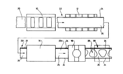
As seen in Figure 1, the facilities comprise a hot.
rolling mill indicated generally as 10 for hot rolling
beams, a storage location 12, far cooling beams, a heating .,;_:;'
chamber 14 'For reheating beams, and :~ motel forming press 16
for forming the web of the beams. Optional further grasses
(not shown) might ba added, for purposes to be described
below.
Referring now to Figures 1 and 2, the stags of the
process will be described with reference to the shape of the
beam rnembar at various stages in the process. A typical bar
or billet of metal is indicated as 20. It may be seen to ba
of generally flat rectangular section, or "dog bone" shape
in some cases. It is at an elevated temperature, 'For ~~xarnple
in the region of between 500cw and 120oc~', in the case of
ferrous metal.
However other metals and alloys of metal may be hot
f.; ;, i; ;: In., i I , , , , , , ,
rolled at varying temperatures.
As the bar 20 is passed along the hot rolling mill line
10 it is shaped into the desired beam shape, which is
illustrated hers as 22, in the form of a typical I-beam,
although this is merely an example and without limitation to
~. , ~n
any particular shape.
-10- ,. , ,.:'
,, .
. , . .,
.:..
.~ I
. x ,.
a ,
. ,
1 .. y ~.,...~....
a
.. t :....x. . . , ....
u. n
! ,:S I.
..d~r. V rJ'.;.. .. 9,.i..;... .
i n . I f
.,i.:..: .,...T. u.
S
..,w,
. ~'. a, ,1,.. i,..
a!..: ,~
I . . ,t
u.
, .d ~ .C. ~. t. , .. r .
f;.,
4 6 .'..:lf: '1...., / , ., rY ' 1
r ,.
, a.
., t., . :;i:,
s.:.
~~, . ,
,..,(.,: ,....
,i , ,:
.,
,; .1K'
..: ,L; ,, r
,,~..r. . .t..F,.. &
y .t,..
i ::
r r ..'yi n a . I . ...
y
. p
r!. . i . L. ..
:,.I f
n !,~:'n
,r~; .Jt,. ,..,,~..: .
. ,. ~ r :
.r - ~ "-,,.,..
,, ., , :-'.t .., . b
Y.. .,. ,.~ c ~:,. . r ~. ..- ,...
n,~7..,,
,. .t. ... , . , ?r
r,~ ~ , ',
il"'~:: n t n r7 :.,
11 r
~r
s,./~ .d. ..;f ..
.r .
,.r' .
. e, ..t., .. I::. .. . t . .
n..
.m"
r.. 1 ...
n -:~ . .,t Jr..:. ,-_n... .
r . .
J i Y
.,(.:.,Yf;....,
...~,:.,'1.. I. n I .. .nS.
,...r ~ 5.-,y
1. l.r 1. . ,x ::..
.,.
,. ,. 1....
~..'. .1 ..
1 '
L.
...1..
.. v t', ,
.~.n.. i.~.. ':.v . v~4
, ai. ~J
I , L
t"~.. ,..c .,
.,.. 7
...r...... 's.:.
r';. ,. ,
m i: ,.
.,Y
. :,
c .
.... ' , Y
.!t~~,: ., .,..
:.., 1 .. .1 r ,7. ,
o,.n, ;..i
.:.~~.., :f ,d,:..
t
,L
.: , .
,:;. ..., ,.::. ,
,..
:>~: , .r':
t . : 4 ....
... I
, '~; , . . .. r. '
, , o.-:.
4
V. r.~r~ d
,',.'
,,
..:, -~ ..,. :
,;: a . .
. ii:.,., I
t ,; .:.;.f . .t :,. ~ I -~~..~! , ~. ,
.,: r ..
. f. . .. ~7/
..2.,.. "~I7
..4~. ~! ..,
t.. ,
'I'
n.:l
!.. I .., a. ~~~~.r° t ~.. ..~.i~<, ( .
'. a 1 t~. .. n ~- .r.i'. J .I . ~ I
,..,. ...I. i~,.., I )'~'
, ~.~ 7 , J, f
,r .. 1. ,.t .4. ,." ( .. c." , ,
.I,t,1 . 1 ..)...i I-.~...,..
.;. I ..,.. ..,, r :'.I. ;;; ' . , ~ ~:~'
r :15' :. L.. ~ .:. ..I:a.~,.....f..'~ ..' p .. L..._
::<' ~ ,: , . u:: ; C . a., ..,... .J. ' 1
7 ,.~I, u. ,..rJ .. ~.1.:,.,,
.~".,
,I, . 1,.,
...,
,.
a ..
r
,
Ix :
,.
,.,.".
.I,J'.r; ...
, -.r r , ,
a,..:,
:7 : , . ~
, n
,r., ..,. - A , f '
,I: i . 7
f
.S_...' ...J ,-,o.
.f..~
.-, Y, :r. . I. ~1
. r7'. ~ 1' ~ ~ : , -.
F , . .a,b.
x. L.. . . 7 r. ,
f.
.m.t' ~s. ~,.,...
,f.. L.t.:~.;.
:.: T
...r..~,.
i~I .
r J:"'.
t ':
. I..,
d .J
S - ..7 :... . Jf ..
t r~: ,
.::J
.. 1 . . ...'~ .. . . - 1 . ., a , . .. .. . S , ,
.N.~ , , . .,.. .,........n,...,A,..,...Yr.,..r....,~. ..-:I . ..r, ;'.~.. ,
,."...... ........, ........-.,.,.:I:........ ., ..... .,. _. , .... ,....,n.
....". "e . : ..,. ..,... .. . . . , .... .
2~03~~2
In many cases the beam is passed first in one
direction, and then in the other, so that it passes several
times to and 'Fro along the line.
The finished beam is then allowed to cool at the
cooling station 12 described above.
It will be observed that the section of the I-Beam
(Figure 3) defines two flanges ?4-~4 of .~ predetermincad
first thickness, and a web 26 joining the two flanges of a ,
predetermined second thickness. The web thickness wil;1 be
' : ..'';,'r
seen to be substantially less than the flange thickness, and
the web may exhibit a certain degree of distortion, (not
shown ) . r
The I-beam 22 is then subjected to ra-heating, for
example in the heating chamber 14 (described below). As r:v
explained above the heating chamber 14 is preferably of such
a design that the heat is concentratod and Focused so as to
heat the web, while minimizing the temperature rise of the
flanges. This is a significant impors:.ant feature of r,.he
invention for reasons which will be apparent as r.his f':5.:
description proceeds,
~,; ,I i ,r ,
The web temperature will be raised to a "hot forming"
temperature. Typically this will be between about S00'c and
1200'c.
From the heating chamber, the heated I-beam indicated
as 22A In Figure 2 is then passed through one or more metal
forming presses 16, where for example openings 28 are
-11-
r . ,
I.
n .:::
i ,
f.,...
4
.f
. r .,'...
;..v
. i..:.
I
S
x ....
d. ..'..S
T f
~.. f
.tJ ...
..I
f.,.
.. .,.." . . ..':,~. . ~,' ~:. . . ...:.. ~ ', ..,.:'1 . ~.:.. f . . ..."' v'
n.. .:.. . . '.'.'.. . ~:'. ,, .'..... :.. .. .'. ~:.' ; ':..
r";
.:f-
x
f I:.,.,
S .~, y.
: :f i
i
k':
,r. .
.,-.u~ r.~ ,. I.,
,i
.r
... I ,'.
L...t .c
I .; , r: .
;. f. ..
:,-" .t.., ~ . i
,: ,
,.k
.f .
t
1
:.:~ y.n
t.
t
.1
.1
.. ! 7.
/. ..
f'i.r
,n.:.t
r r
..:.i.... . t.,. .
n. , t. ,
J: .; .'~ I
r
.,d. I,.
s, .t.
n.:
d.
.r...:
n ,:.:
~:,5 ,.
r.
L... .
r
..~f.: .,..h:
l ...
.. r '~' h w
.. J.
tah
xn
f Y ;.
a,':
. .t ...
v ..
x
.r ''
>,
1:'
n ..:v:.
:i;
G .: t
I
. .n, -: i, , .,
r,
t,
i . ....,5.. . .4
v
f
.,''i .
' ,
r-.,
.' . 5.
.. I . .
. .~ :-.
.,,;,
of ..
r.,
f.l. ~. t.
.:G'.:v. . .
y .
n ,
>M
..n .:.'.a' .
I,
w. t
.S a
S
,. i:.
.l ..
fY
:..!
',\ ,f r ; A
I
S ..
..Y..~
1
!.,~n
V
. I .:':'
y} . : ?:
z ,
< n
f ..
i: f.
r
I . :.
. .r.......
J
r. .
1
:.. f
f,, .' ::
~ ...... . ~.....: .. ~'.: ..':': ,: . " ,;:.. ,.... .. :.- .':.':... . .. .
:, .. .:-
.?. ., . . .... ..... ..~: . .. . .. : ... ... ~ ...,..a~.:... ...... ,.. .
.......... ,. ,...., .. ....,.. ,..... .v.. .. ......., ,.....,..:.:~.
5.:..::.,: ..,. .:v.. ...,:
2103~~2
forrned, with lips 30 (rigure 4) formed around the openinga
at an angle to the plane of the web, to provide the finished
beam 32.
In most eases the openings 28 pierced through the beam
will be surround<~d by lips 30, in order to provide maximum
strength to the web,
In some c:~ses however it is conceivable that the
openings may be pierced without such lips.
Figure 5a illustrates .in ;action a beam formed with
openings but without lips.
In rigure 5a the features corresponding to Figure 5 are
indicated with the same reference numerals, with the suffix
a.
The dies (Fig 9 & 10) in the press era so designed as
t:o form the wob, while leaving the flanges untouched. Such
a typical die set is described in more detail below. In
general however, the di6 sat in the illustrated embodiment
.is designed so 'that it will punch or pierce an opening (or
two openings) through the ~heatad web, and preferably
simultaneously form lips, around the openings. Preferably
., , I ;, i ' , , I , ,
alsn the dies will have flat planar forming surfaces around
'
y:,:;.::~: ,;w
!,
~;;::;;:
the punch formations, which planar forming surfaces will
engage and form the web around the opening so as to render
the web flat, and to correct any distortion that may have
occurred during rolling and cooling of the beam,
_12_
;;
e:
- a ,.
r
, . r.
'
r. P Y. .,
i.
,,
::.1.,=, ::
:i
"
9
r
"
,
r,
..l
.
,
t,
a
:"r.,ra.
.,.
r
.
...f.
.t
..
k
,
Z
r
':
x
..
,
1
0
,
,
,..,~..
r
,
7
.:,;
,.L..:..
.:'
(,.
q.:.
i
1.
.,
rl
,
f-
r
,
S
.t
N
v
;,t:
a
~:'
Y
,
d.
y
,..".r
n
,
r
,:~~
~.e
'
'
.'
:'-
~
J.
,
:ro..~.n.
I
n.
:
i
r
si
.
r..,
..
-
Z,
..
.3
.,.,.
~
,.Yt.
.
r
t
,;;.
A...
r
f
'
I
l
'
'
"
,
P,. .
, ..
r;
,
. fi
;t a
..,i"..., . I. v...
,. ,2, ,
iS C.: .,
~ . >~'. :. , r ,:.:.
r . - r . , v:::,
,,
,.~.:-.r:
r
p
.
''
f. ;
:: .,v.
'. :: t"
A ..:.t~: i,n . .
,1, ,
. ,,i..
r -r,...
, L .>~ r J
1 ,
l :'~
i.
a
,
-;: 1 ,;.
4 ; r~:-
::a
1
r
S
:~ ...
r ,
1t'u A...,
! -.
it
' a
:
i
t
, ...
,
..
5. ::
; r ::.
,I
f y
.y -: , ,
:;J: '.r.,.. .
. r. ::. . Y
- i,:, r. a, t: , .'1
4 r;..~:, . ;: .[;
.fn. .I , v..,
r' ,.! . ~ s .'
r. ~ w...
4 ~: ~ . ,
4 r .. j . :,.~. , 1, : . .I '- . n .
i,.. ::.i",..,
.f ,
a ~ : .~
. 1
.i
:r
~
~
f1 '
:
y
t
'I '
~
)
.
s .
,
..
k' . ...
. .
. .
........ . -~'.
:
,.....
.
., p,... .. ~.,,., , .
,o. .
..
r 1.: ...,,y ,..
.>
,
.
...,V,..
,-, 1:
7 :
i'..,:.9
,.
..
. A ::. ,
.
.
' )
-
:
~
~
T
. ..
' Y
2, -..
,
1 ,
l
P, .. .
t ~
7
v:~
~
r
, .
.,1 -. , ':
n,: l , .
1
ir
.
v. . , r .
.,, 4
),.._
I r, t G::r:
)_
s.. :'
S I . i
,. I.
:''1. ~ ~ln~.'.
2r' '~ A.
. _.Y
,1. A~ .
. .:
~~-rJ';
,. Y
.r
'
i
.
. .
1 ,
n , .
. ,r
K- .H. Ia
km.
t
P 1 .
.P
7
. 1
, If
v,JJ:a~
' :.
,
t
1 ,
:li
f,.,'~
t 1
~I,
r '
r
~
nl ~
.. ..
t .
. La
~
,
v . :r
,. , ~,1 1,
, a.
.,L,, v ~". , ,"1 :;
.I ": ~. .-
. .. 1 .
.Ir ~ , r
,,,
H . ..a,. ~ _I
t . t... .
r ,4
1.,.
.,:, ::
,. y . , .,
.,d
,r >. 1.
f
'
.
I ,
1 . ..I F.
W :
7 , ,,
1
t :1
VI ,
', ~, t ~'..t.,:
). 1... . .
I , ' '.'J: ~ L .:. J .,
..r
f
~.. 1'.:
v
:i
1 i i
t
:'
~'
t
, f
1 ..
I ..
, . , f.. :.'.
...
I .,
. .t
P S :..
., ,., f,..i
w. . T i
a f
W I 1 .....~..,,, 4
1, f' '
f'n. .l J . -.!
N. !
1
4.n.. t .."7
":.N .
7 I, t
". 6 r "D o
h-
tl: . . :i
', t 1
n
f
=
r
A
I, . ,.
.
.
.
-r
,n
S ,.,.r ,
" "'i
t. t
5 i
F
t.>~., , 5
F
~f ,t
:.1..'v"
,
P .- t t
m
r iY
,
,
n ,
i . _ t
t r ..
x7 .
m.. s
,7I ..,1., .
'.. of
.. k ',
i
f .rf
'. a
,
) .J.:'
A , .
~:~
I,f
5
.
.
..
r' . , .
. 1 .
'. 'y,...,.. ..:?
, r ..
su., .:,. .. . r .:i I
n,;':~3
. . . ,. A.. r. , ., . " ... n .. ...,.. ...,. < . ,. , , , . . ..,.
, ~..,. ... ".. _ r..7. ...- . ,. .... ,. . .. -. . , , , , . . a
. . , . . , ,. . . , , ,., ,
?1~~~~D2
While the openings may be of any desired shape such as
circular, or in this case generally triangular, with ro~~nded
corners, the planar forming surfaces will ba rectangular
so
as to engage and form a maximum area of the web, in each
operation of the die set, so that each time the die set r
1
+
c
.
.
closes, substantially the entire area of the web rernaining
around the opening, from one flange to the other, is
r < n~:;:;
flattened to correct distortions,
For t he triangular shaped openings shown .it would be
necessary to provide either two punch dies in one press,
or
two presses, each with a single punch die.
The punching out of a portion of the web reduces the
overall weight of the beam. The forming of lips around the
opening, and the forming and flattening of the remainder '~'
of m YI
:y ,,
~ l '
:;
the web both flattops and strengthens the web. '<r'-
r
After cooling, the flanges of the beam will usually be
subjer-tod to a straightening op~ration (1<nown per se) which
is not illustrated.
In the end result, the finished pierced web beam has
load bearing capabilities substantially equal to that of
a
; ,. ~ '
'
,
!
standard, solid web beam o~F equivalent flange dimensions
and
'' equivalent web depth, while being much more economical to
produc~. In most cases, the finished pierced wake beam will
fiave a web thickness which is substantially less than the
web thickness of a standard solid web beam. This is because
by the operation of the press, or presses, on the web, web
-13-
~1J~~~?
distortion, which would otherwise result from the reduced.
web thickness is eliminated by a hot stamping operation.
Thus not only is substantial web metal removed by the
piercing of the web to provide the openings, but in
addition, since the web thickness is reduced as compared
with a standard solid web beam. Thus the overall weight or
mass of the beam is substantially reduced as compared with a
solid web beam.
Major economi<~s result 'From both F~atura of the
invention.
It will ba observed that the openings 28 are of more or
less triangular shape, having rounded corners 34 with a
relatively long radius, and linear side edges 36.
The triangular shaped openings 28 will be seen to. be
directed alternately towards opposite sides of the web,
thereby defining more or less diagonal struts 3t3 of the web,
separating one triangular opening from the next.
The Flanges 30 formed around the openings 28 will thus
be seen to extend along either side edge of each strut 38.
2U Tf~is ar-rangernent of struts and flanges, forming essont.ia.lly
,..,, i ,~ , , ,
channel-like shapes in section, gives the web great
strength, notwithstanding the removal of substantial
portions of th~a web metal at the openings, and produces a
significant reduction in weight, in addition to the savings
in weight achieved by, in most cases, utilizing a web with
2~~3~~2
considerably reduced thickness as compared to webs of
standard solid web beams.
Furthermore, the finished pierced web beam has many of
the advantages of castellated beams. It has a much higher
strength to weight ratio than a solid web beam, and at the
sarne time it permits the passing of services through the
beam. Thus the advantages of a castellated beam era
obtained, in a beam of equivalent size to the size of a
tandard beam, without the additional depth of the
:,, ;, ;,;.:r :r;.,<
castellated beam and without the greatly increased cost of
the castellated beam. Such a piarc.~d web beam i:~ thus
directly competitive with a standard solid web beam, and
from many aspects has considerable advantages as compared to
a solid web beam.
In a typical case, the piercing of the web of the beam
to provide the spaced apart openings will provide openings
which extend across approxirnately 75°e of tile width of the
web, leaving approximately 12y of the web metal remaining
on each side of the opening.
,, The actual metal ra~noved from the web will usually be
I, ~
in the region of 500 of the web metal. This will give an
indication of the major economies that can result from the
invention'
As already outlined above, still further strength can
be added to the web, by the provision of generally
-15-
,.-..r.~,;. .rf ,.,
t... r ..1:'. .
r...
,. t
... r
,.t ,
~ I.
>!:: r ...
t. .
r':
. ::l : 't .
r r
J . .'
v . - r ..:.~5'
t
' ,.
J.,,
.$.
s
I , u'
1
4
. t u:
Y ,.
a ..
i .
A If
A
A
.K
I
7
p.:~~
ti ., y~
1 . .
.,:1
.:Y ,'.
~.+,. ....d
i ..
I .....
,f,
:i
.ri
1'.
s~
J . .F
t i .. -t, . ..... S
., Y:n .'.r
. t
,. -, Ii' " v
4
..Y
_..t' v~
:Y'
f. S
.i>';
1 .. .
a
.:~a
.r 1
.1., n L -
P.
7',: .i , I
N~ ,l :. . 1
5
t h =>,.9.-t. . I... n
77".- ~ j 7 .:,....
,S ?~~~~ , l..
I ~.~ Ir. ~: ..>
.,; y'r , . ~ ~ .. I Y
P r:l . ..,6..
~ .. n. ...
JY.r...~.w,....I, , f~,.,.>.
v~...
,: .,
4 ,.
a:
7. .
l
".,'r
a
.,
1 :.,
:..5
n i
>.:. ' n
a
tt. .:~i r ~ .
~:<.:r . , r
>~ r
r ,
v . ,x.. ,
,. n, ,t. ::.
r; .I ..
4
. f Y.
r i, ~
1 r ~ r,.. ,r
i
>r , >.., .,.
t ~ I,. .n ~.F~'.,
f, ,
J
:'? 1 . .. .l... . 4 f
JJ. r, . , .Sa L.
1 . 7
.4
':'.l. h. r.
ry r .
. 1,.
. t Y ,~,:, S " ,t'..'"
t
.t \A ~.n
. r,,~
, r
v -.~
'1 . f
.t. ,~. A. r2.
~r;.
r ,4 .~:,v . "S . .'J .
.1 : -~ a
P. r ~., ~ 5 ... 9 ,
4. ,
.. .d. ~~ I ~.
f ., m, .. ~ ., ,. .w ,s ..:: , j..,l . ?ib
:r,, r...... - J' x ... . a , ~ . . s t. . ,. t - sn
1.
r .
t, s:., a
~t 't . ,' , , n..f . ,
1,
:.., p
5.'.~ 4. ~.v.. .. h
.7.0
t ~ vtn°.. : 'f, V':ai
y ,.
.. ~ks ~, r , , snr,.. ..
f..: ,. .; rr4"~ ,..
I
.~ r 7.:: a x ,
n." 4 , ~ . I. n..U . .
5 :~:r
~A t 1.
,: s 1
"S ', u~- s, . ~ ..
1, , .:a, r , av.. . sx " , . (.... n
;.'a . , ,. s
: !'~,'.: T . ~: C
!.. U n ~.J ..
1':. : t. W ~., . . .1 ,JI..., f
,.
r.. ,. ~ a m -
r . t, ., ~ at:~... a>;~.~,...:
..l, , s. .
4 . ... / .: . T ~ ~.:- 4 .t -n"~
~Af... a '~~! I
I . f... 1 .
. ( ":: d~.i',~
!' h ..
.~j .f. 1 'e I
S . .4Y
y .. 7
1 .1 " 't a .1 :...'.
r o, n t
.S',, '~
t :..~
...' ~ :t .
'~. . :;.~ J
Y! . 6~:,f.
.'.rr, .at.:, 1 - n
I .f, . =., f~ :,Y :.
A
r,~. , .~, t' h. . ~ , r .. , . .
.~.r
r I
niC . :f : ~ . 1 , d ~:
,..'J.... f
..r
S:.,t. s...,~. .. .4.v
I
P : ! ~:
.. .~;. ~ I , ,.. ~t r,.
.,y..f r
a . , h:.
...:5 ,i. rn.,.
)
f .. :,~.~. i
.n
.::.,.r t,
S ., ' ,1,:'~.
l :'f
J,-.., ay' .,.7'.i~~..
.. r..., ~',':r fr..
a .. .A :,..,J p
., ~ , . .Y.n
[ .. .-,:l-~ ~.. .,W '..;
.\S, ~... I : ,'..a"
t. ,
4. '
.i .
..
\ .
. 1.
y I .::N .:':$ ::'A
1 f ,
1
h : ..
-i W
,.5~: , '- >, .,:.,y.,., t. - ..f,-:;.
1 ~ .I ., , s ( ~v
w .:.
J ..
~.a ~. ..
n
..4f 1 r
.,.>.,..
o W, a
,u ~ r" ,
.d. t ~
Y . :!
1 r
f..
f
i d .:.,
~. r::
! f ,. .
.., t
N
,~ y:
f
r :, , ._ r.
:,
, f
r .,. .,
t;
.r ,
r.
J
y ,.
1
h
., 1.:
Jit,
. wq ..
t
I .'~- ri,:.F: ~:.~ . _
4J'r,::.4.1.. ... .. .. .. .. ....;. 7,..r ._... a , ... .... ..... .. .. ..
... a .. .. a......n...... :.N....!~..~1..~........_ .i..,....,.... . n..., ~
n! . .:, _ , . . ,.. ..,
triangular indentation 40, at each end or "root" of each
strut 38.
Each of the generally triangular indentation 40 will
be seen to have two linear sides 42, and a third generally
cured side 44. One of the two linear sides is the base of
the triangle, and is generally parallel to the flanges 12 of
the beam.
The generally curved side 44 is adjacent to one of the
curved corners 34 of the generally triangular opening 28.
The radiusing of the curved side 44 is arranged to
complement the radiusing of the corner 34 of the opening.
The other linear side 42 is more or less parallel to
but spaced from, the other side of the indentation.
In this way, the generally traingular indentation 40
form two strut root portions namely a linear strut root
portion 46 and a curved or arcuate strut root portion 46.
This feature adde still further strength to the web.
In a particularly preferred embodiment of the
invention, the beam will be subjected to the action of two
or more presses end die sets, one after the other. These
die sets will perform a series of operations on the web as
illustrated in Figures 6a and 6b.
the objective of this series of operations is to form
an "added value" second component from the portion of the
web which will be removed and normally discarded. In the
-16-
z~o~~~2
simplest case, such an added value component may for example
be a washer, although this is merely one example of many
different second components which could be manufactured in
t his way .
Thus in order to form a washer as a second component, a
first die set might punch a central hole 50, and a circular
washer shaped portion 52. The second die pat would punch
out a scrap portion 54 to form the main opening 28 in the '
web surrounding the space from which the washer had been
removed and would Form lips 30 around 'the opening 28 and
flatten the remainder of the web 26.
These various steps are shown separately, but would be
performed in two die sets, or conceivably all in a single
die set .
Heating of the web, without heating the flanges is
E3fficiently performed, as showed in Fiuures 7 and 8, by
means of upper and lower electrical induction heater
elements 56 and 57, connect:~d to a suitable electrical power
source 58. '
Such induction heaters may be located for the sake of
;, ; , ,
convenience within a suitable enclosure or chamber indicated
in phantom as 14. (Figures 7 and 8)
However, it will be appreciated that in reference to
the "chamber 14" this can also be interpreted as referring
merely to the space between 'the two induction heaters, if
z~o~~~~
for any reason it is not desired, or required to enclose . .
them within a chamber as such.
Such induction heaters are known per se, and
accordingly the details are not specifically illustrated.
Ioducr_ion heaters of a suitable heating capacity will
rapidly heat up the reduced thickness web while the beam is
passed directly between them, so that they can be
effectively used in a continuous production line, just up
stream of the press, The induction heaters era of .auch a
design that they will focus the heating effect directl; on
the web, without substantially heating the flanges, so that
the web may be raheated to a "hot Forming" tcrnperature,
typically of between 500 to 1200~*c, with only a modest
temperature rise in the temperature of the flanges, due to
transmission of heat from the web to the flanges.
Induction heaters of this type can thus "focus" the FK'
heat directly on a desired portion of a bearn. However, other ., '''
wx~..9..C
.' r
v..
forms of heaters may serve equally wall in certain '
~
;., .,
:x,':
circumst~.i~nces, such as gas burners, and other forms of
l~f ;:;
,radiant heaters, all of which are well known in the art ancf ;.
,
,~ ~ n i ~ ~f ~
; Yft 'v
, ;:
require no sp8cial description.
By way of example, a typical die set for use in a
;.
stationary press is illustrated in Figures 9 and 10.
'.'.J.,
It has conventional upper and lower plates F,0 and 62 '
and guide rods 64. The lower die comprises an inner die
portion 66 and an outer die planar forming portion 68,
18
,I
,.... !. :1:
~. r
.~;.rr, , . f :'i
..:11,: f, ,
,:;.
.,.,.. .
I ,.1, . S !'..
J /..
:: a :.;"
, .r..
-:
. r. w.: . .
r v,. .
' 1
f I,
.. 1 ,.. ,
,.P',
s .
y
1.
n.. ..
.J.'.: .:.:
.... r,., t n, ~.r,
4 r .::7 .,t......i7
f .....
.I r'.
..,Y ,
::J. . u...
..n.
~f. . ~ I
~
.
. ,...
,
! ,
n. 4
l . u. i
f : .
I>:'' ~ ... r I. .
L. .
.,.
.
.
y :. .
w....r
.1
I I -'
f
.
7 ..
. .
J .1 ,' C ..
W.
A ., .:.i...... 1...
..rl. -1. .:.1. '. ' , ''
. ..1 ,.. ' ..y.
., L.. .1 .. ...''.
I!F . ..7.
..., t
,I., . i
x: fir.'.
, .. y ~..' . ', i ..
/..n ...7'..
4./. L..
.. ,..
.: . .
..:'. I : . ... . :~-
: I ' .
::::
n
~
~
.
.
, .. :
.::.....:..
. . . . :';.'!
.
.
.
.
.
L':
:
. 7 ~.:,
' J f..~~ .. ..::.-' ".. .,.:,.'. '::. .'.:: .....":.: ..e':i: :~
...;:,.... :,::.~..: y.' , .::: ."..:
J: A
hrr ::: tl , .I,.. ' :..., ..
,..r. fr
. r',.
. n
1
.
..
.
,.Ir
Y..
r ..
y
..1..1
,..:Ih'. 7
1 : ., 1
'~:.n . ! / . n 1 .., : ~;
,~::..
i
W . . L~.... .1 ~.
.t, (:.
. ~I ..: .,.., f..f. n..':.
L.
.I .,. .~".. . ~,.. -. .1... F
'y a ..
~y~,y .. "::~'L,.
1 .:
8 f' ~' .
.WI . ., . . !..,.:.... ... ' w.. ~.:~.. ~'~. I. .::.,.n.....,..
:'..t .,:.'. '::...,. .:, ."..... ..:' :,I .~:'.:. ~, , .... ..' :
,,'~, "
y~
..
1 .:
...
. : w,
.:.
' . .
.
~
~
1
'
'.'
'
:
~
'
'
,. , .
, , ,
., .
. ~.:
. .. ; '.:'..
1.,. :
.
,
,
.
...:
,,
S 1 :.
:.. ".
::. -~ ~'. '~ :. ..'..
,I, .'1.::
...:' .:.:':',.
611 ...~ . .'
. . .:.. . .': ',;:' .. .. ~...~, '..'' .~ _.;..:.1.: .:."".~~ ,.,:::
..:.:..: .. .i~...... ,,' ~".:. :,.:..,i, .
t rarl. :V. ::
1
~. :.A
~" 1
l
:
.
f
I .
:
.
1:
:..: f
~.
1 ..
IL~. '
f .I
w J.. 'y
u. 1 ..
7
I r
f . '.
t
.1 '
1
. 11 I".
t
. .11, i '. 1
!,
i
1
W
'
. ,
.,.
... .
l
f I
I f.
n .1. V ~.::1'
I 1 t. :
;;
role, ,.i
f, ,.
. ., . . . . . , .,
. '.. ... .. ;..
~ . . .
. : : . ... . ', .
i :
'
'
'
'
'
~
.
. ~.: . .....
.
. .. , .
.; . ..
., , ,,.
.;.; .: . .
: :. .. ::':.., - .. ,
I .,:.'.' ,., .,.1.,; ,
,:;: , ,.y :',
-.....::
1~
:. ...,..
(..1....,
'.. I;.L" ..:..;1 .:~: . :.:.::.:... ..~ .:: ...:..:.... ,."....
.... ' .:.;:;::, :..::::-. ..:'.,...,..: ..,... ....... . ,.::..
,..,.,. , .. .., ..~.... . . .,. .. . .. . .::.'.: . ::-..: .. :.
- ..... '." ..... ,r ..... .. .. . .. ' . ,~,.. ... , . .
;'
. . .
..
.
,..:.,.,. . .:: ' . : .
.
;
:
'
::
'
-
~
, ,
." ,
, ...,.,
. .. .., ., . . ,
, ."
. . , . .
.,. . , .........'.
,.. ;
., .. ..
. . .. . ..
. . :. .....:.:. .. ,.....:... ... ...,.... ...::.
..;: :.:". ........ :...... ' ......,::~.: .' :...:'. ."...........~,
......
~::~;!:II. ' '".:.el'.~:.
I. ..r.,v "..: ..... .. ,:I',. :.:...:............ :... ..:. ::,:
:.. .. .a...,.......,:......, :... . ".. ...... .... ,....... ...::........
.r ... .,,,. '::.r: '.~~ ..:n,.:,
'S 1 .", .. ,,:: . . '. '. . :' . ::! .. . . ~ ,...... ~. . ; ~..,.,
, ;:... . .. ::::: .:.... :: !:;:
.
.~.
.
'
::
:
v
;
.,
::'
:
'
,: ; ,
.:: , ,;: ; . .;
, ,. -., : . ,;... ,
..; ..; .. ,
: . ..
:
:..,.. ;:.: . '.:.'.'.
i:. ,. .. . ...
v. .
.
:.:
.. ... .,.. . , I. ,... .. .. . ...: .. . . ..,. . "
....:, . . ., : ; .... . .... ._,., : ,. ... .:: . .. ...' .. :
' .. . . . , ..,.
., ..; ........ .. .., . .:::. .. . .. .. .... " .
FI . . . _, ....1,~.~;;: ..; ,. ~.... :,. .; : -,:,. .. ~. ....
...... - .",.. .. ,..:. :. ,:~ ", -:
,...,
. ...,. ',
' ,;.. ..,:....
.
.:.
,':..: .~..:~
-:.~::
.:
.. '.~ ~.,.
. .!.':.:'
.. ,...
~~: ' ,..,'-.......~. .
'
~
. .: ..:
. '.
" ..
.
,
.
...,
.
.
...
.
.
..,:~: - ,. '.:. ~:~...~. .....,,.,.'.., .." .:. . . ,.;.. ...;.:
:. ,: .":
......,:,. . ' :':' ..:1:.". '. '.J. .......
1",.., ~ ., , .........,. . ...:...'..... . ,.',..._. .. . ... .....
.. .......... ..
21G~~~2
together supported on a platform 70. Lower die portion 68 i.s
moveable upwardly and downwardly between the positions shown
in Figures 9 and 10, and is normally urged upwardly by means
of springs 69. The inner die portion 66 has a inner cutting
edge 72, and a generally angled forming shoulder 74. The
outer die portion 68 has a flat forming surface ?6.
The upper die consists of a central punch portion 78,
having cutting edges 80, and spaced therefrom by a space 82,
there is an outer planar Forming r~i:~ portion X34, h.~s~ing a
rounded forming shoulder 86.
The space 82 is adapted to receive a portion of the
lower inner die 66, as shown in Figure 10.
An upper die pad 88 supports the inner upper die? 78 and
thQ outer forming die portion 84.
~uitable fastenings and bolts will hold the various
components together in accordance with well known practice
in the art, and accordingly are not illustrated.
Tt will be noted that when the die set closes (Figure
10) tho discard portion, which may be the shape of the
"added value" component 52 (Figure 6a), or may ba the shape
: ;:, : : , ~ I, ~ ,- ~, I , . ,' ' , 'a
' of the discard portion shown at 54 in Ffigure Sb, falls ky~'i~
downwardly through the inner lower die 66, the web having ''~r
.,
>s 3~;
been cut between the cutting edges 72 and 80. ,~t~:
.
t
ip , ~.~
r
As the die closes further, the upper outer forming die ~
,;~
s
.
,
~t;5~y~,
'H'r
r'~ ~7
portion 84 forces the remainder of the web downwardly ,
~;,"~r~~~~,
4
,;.
-19-
,~,..
t,.. .." ..,:.., ,
-: :"
) ,, 5 .
.:: >;:
,.,
.,. .,
L.., t., ;
1:
W 1. I
. ;.
I ...
f .::1, . Y :~.
. :
i F
~. ti -;
. 'f n
1f j
rt -
'
'
. .
.. .
fi .
. .
. ;4
, ,. :.;.'
..t....
9 ...J...::
.1..; .
. i ..t ,.
y ,:: 1 .
,. I .,... ...n...,
. 1. ::.' . . f . .1 .. 1, .
I. .
r
. ~
.., v., I .
1
,,
l
,
. .
. :, i
.h
n :. t ,:.. . . .Z ,
..
,1 : r
a.
f, ..1, :...
!' 1
., t ,
..
1
:
1..,
Y ;.
v :v
i a....,. ,...<- .
,...n . I :;
.:e..
z s..
,
a': .
i ,, p ,
.,
.:,.
.. r .. .
:,:
.
r. 4,
F
'r , r... r
i:..,.
Y
. .f,.
~ :
I I ' y .
~.sy-..,
.i e
i,.f
:r'
'
'
'
'
;
:
.
..
5s 4 ,
1.
.,f a:
.
~ ., t,
i..;'!:. i ,.
n. ,:.i
j..
.. f. . .,
1 . . 1. .
. ). ~.5: ~.u 1 . 1
, I . .b..i , .. .h ( ,.. :...1 .
. .l. ..1 ,: .),.. .b
3 n I ! '..
t ...3 i .. I. ..
... . .r . ,
. t.,.. . . ,
,,t.. .. v!. f; 1:'
7 ..:i.,.: :.. ~. . . . .. ,
I :.:.t . ...
. m . . i ..
- .
.:. ,..
'-' , ~ . ..
.
I .:
.. . .. .. . . " . . . ,, ,
t ,.:, , . . .. . . .r: . , ,.
,.., ,. , . : ., : a :: ,......;, ,... :. .:.
. . : . ., :;:. , , .: ..:: :. ..,.... .- ., ::.:. : .. ..,
~ _ .; ,,:, .. ... : : . .:.;:: .,.
1 w
:
'
~
. . . .: ,.
, .. ...: ,:... , ..~ . .. ....:, . ...; :.1 ...,
. .. t .. .,, . . ., . .: ., ,. . :'.:.:' ,.. ,
.:. . .:. . ... ... . ....:
I, , .' ..
,. .:...'.,. ., .,...:..: : :.,.,., :..:: . -. :.......
..1..:,... .... .~ ~. :...., , .
,... ..:.,.. ~ ;
.::. :.. ~
~
' ~
~
~ '
~ -
~
, :.. .,
.r.: ... .
....: .; . ;. ..::1,. ., ... : ...,::..: .. .
,.:. .. ,~ . :....
;:. .::...;..: . ~.~.' : :;.. . ~
n L.. :
.. .r ' .
a .
,.:
.v:-..: ~ .. .
. :...
..r.. ..
....I'(.
. i ,I
Y . ..:.., ,
J ..J., .-
...1. ..
a
. ~
::I
..:
.
.
i :
... nh. :. .1.. . .
..: :'
l..
5. ..:,
3
t
1
a
... ::;v ..
1 .
f
,.
.rl.
t,
1. ?. ,; ;
t. ' ; :'.
a
. 1., v::.,. : . . .
I ; : ..:w .
. ..: t ... . ' ' :. ..
.. . .... .,.
., ;
l ~ ~
,n.i . .
..~.., .
- . , .::. ... ...: :~:
. .. . ....,..: , ....,.
..:..I'...,., . ,. ,
v ::r
''... ,;:, .,:, ~::.. ; :..'... n.:..~
:.., ~: :...... ': '. ; :...;._s ::::
~
, .
n ..:,.:,,::;. . ..,
" :.. .;,,;:. .. . ..,,.... , .::,: ...!:.:. t.::,:.,,..;:..::'v.:<...;.~..
J..1 :~
. , :1 . ,t ,
~o ...;'~... .. ~:.::
; f....,...:.,.' "...,..'.:~.':",:... ,,'... :."."...~.:....:,::.'. .',~.
s .~:....:.. y, .......,.::. ":..~.: .',:....;..,.
d.,. f
r..
. ' ~
,. '
.
.
.
:.
:' .v n
.,,,.:, ::.:.',
. , .,....:.. ,. ;w.~
.::".;,.'..~:
Y'::. ':'~ ... .:,:.;. , . '.., ~
~ .t . ..;..:.. .....:.:.
rl.f.~.: '..,::..... ... .,,:.. o..~...~.':... . . . ....... ......~..
.,, ; ;:.:.: .. ......
..;. ,.,1... ...::. .~ '. ' :. ..~,.,...~:..:::...:.: , r ....... .:.. ..
~.' '.:n, ..,....:, : ~ :..
' . . ...: ..., ~...... :,...~:. ...:...: . .; :. ,, .: ,
. ..... .... ., .. . ........ , .. ....:..... .
.. , , : ..... ::.:.. ~
.. ~
..
.
~
~
'
r , . ;.,. .
. , . .: , .. . .:
'.f .. .... .. . ,..... .. . . , ,
'.::.i.. ,. .: ...., .., . ..
c7.:...........:::::'..,:Y ,. . : : .:
. ... ~:,::w...
....::::...,..
, , ..., _. . , . ..
:::" :,.. ..,,.v . ...,.... ~..;:.~ ,::;., ..... ... .,.......
.......,..,.........
. :, ... .:,.,... .:.. ::: ..: , ....,. .,,: .. . ..... . ,..
., . .... ..;:..:,. :.....,.............. :. ..:.....
. ..,......... ,._~._. ... ....... ..: ., -...:....
..,y... .,::. . ~:.. .:..... . ..,.. .:.
~103~'~2
against the lower outer forming die portion 68, and against
the shoulder 74.
The lower die portion 68 moves downwardly (Figure 10)
compressing springs 69. This flattens the web, and bends the
lips 30 upwardly as shown.
This therefore forms the lips 30 around the openings.
Throughout this operation, the 'two flanges of the beam
are left outside the die and are unaffected.
Spacers 90 may be placed on either side of the lowr~r
outer portion G8 in order to align the beam relative to the
die set.
While the invention has been described as being carried
out using a stationary press or presses, and a die set or
sets in such a press(s), it will be appreciated that in
order to speAd up the operation it may be desirable to
replace the stationary press or presses with one or more
rotary presses. One such a rotary press is disclosed in U.S.
Letters Patent Na, R~ 33,613 Granted .tune 28, 1991 Inventor:
Ernest R. Sodnar.
left at a lower temperature, that it is then possible to
pass the beam through a press, or through a series of
presses, either stationary or rotary, with dies forming the
web, without contacting the flanges. The flanges being
straight and rigid and substantially unheated, enable the
beam to be handled, while the web is formed hot, without the
need for any extra support for the beam, or other special
handling equipment, which would be required if the entire
be3rn, ie. both flanges and web, were heats-~d to the web
forming temperature. In addition, by confining the heating
only to the web there is a substantial reduction in
operating cost, as compared with reheating the entire beam.
As an example of the savings that can be achieved by
the invention, the Following figures may be compared.
standard 400mm I-beam ( typical )
Flange thickness 8.3mm
Web thickness 6.3mm ,'
Web- no openings.
Improved 400mm I-beam ( typical )
, ~ { ~.
t ~,
,y
Flange thickness 8.~mm
dr " ~ ,,
Web thickness . r ~'~!~
3-4mm
s' ~ ~:'
Web metal removed at openings, 50% of web by mass.
Standard 600mm I-Beam (typical) ' ,.
Flange thickness llmm
~~~3~~2
Improved 600mm I-Beam (typical)
Flange thickness llmm
Web thickness 4 to 5 mm.
Web metal removed at openings, .50°s of web, by mass.
Standard 800mm I-Beam ( t;°pical )
Flange thickness 38mm
Web thickness 2lmm
Web no openings.
Improved 800mm I-Beam (typical)
Flange thickness 38mm
Web thickness 5 to 6mm
Web metal removed at openings, 500 of web by mass.
Standard 1000mm Beam (typical)
Flanges thickness, 2lmm
Wpb thickness l6mm
Web - no openings.
2103~~2
It is not possible to give examples for all
specifications of standard beams and all specifications of
irnproved beams .
From a study of these figures however it will be seen
that major savings in weight are achieved in the ~OOmm beam,
and that savings are also obtainod in the 600, 800, and
1000mm beams. '
Thus for example in the 400mm beam, tha ratio of flange -:r
thickness to web thickness may be expressed as follow ;
Standard Beam:
Flange thickness to web thickness ,f?
1 . S : 1 ~sw:~'
re.K",,.
Improved Beam: ~'
~
,
;
y Ail
Flange thickness to web thickness
'::
by -it
5
x r; vx:'
n~
r
~ ':.
' y
J 1 . t
l,
S
..t~. .S~.i.;l
These ratios give some idea of the savings achieved by ~"~'
7~~Y "T
:
1
~
.
:
~
i
the method .in accordance with the invention. Tha savings are r
:
r Mr ~~
~
~~~,.~;
~~ ~ ';sr,
~~
achieved while maintaining substantially the same load ~
r~~'
f
! ~
,:.?',
carrying capacity as compared with standard solid web beams ~J. f >l
; ,
,
,;",
~0 having '.~ -~,
the
flanga
wi
dth and, thickness, and
e
havipg the
sam
,
,
;i
I,
,
.
,
, ;
srama web depth. It will be appraciatod however that the web
thickness in the improved beam is substantially less than
the web thickness for a corresponding standard solid web
beam, in most cases.
Clearly however if an engineer requires a web thickness
~, ;'w',
r
that is greater, for a beam having greater load bearing .....
-23_ yf
...,
''
.i
r
r
v:
f
a
~
:.:
:
.,.:
;:.
;;
,
;
.
.L.
.
l
..
.
.
:;
:
:
:
.~
'
~
'
H
. .
~i .
. . , ,
f ... ~ '.. .
ae .
".m... ,
. ,..
... ...
:~
n,.
. t.
,. .5..
:/:
f
'
'
,
'
:
~~~
:,,
t, 1:...
1 . I i:
i ~ .
-. '
~. . ."
~:' t-
r ,h:.
...,.s . ..i ..., .,.... ..':' .:. . ::,:, .
l . ' . '~ . .,.; . -' ~ ...... - :~. . ,.
~~ t '
t
. -
.. . 1. .',::'y
.1 t:
F 1 ':L,
;. f ,~
...:,i. ...
fi t .e;'. : t .
~. s
r ..,'~ ~": <
.
w'~Qii.i~.~. Y
~ 4 >.. .
.,..,~i~ ",: ... C' . .,
.7
I
y ..
rY't.i3.::.
..3
s
: v
:'
''
4. -
t
~~v
K
h
f
:a
~
s
-:~~ '
.
:
. .
7 . '
.
n .
i .
..
, .
.. . ,
, , ..
.
.. .< ...r.. ~..,
., 5~ .. ~.
x ,
. Y':, ... ..?. .'.,
'.
..'IYv'
v,y~.
..x..... ...~'.. .. 4 n
:)
y
...:u
9;t
,:
Y"
.I,
.
.
.
' .. . t .
r.
1 .
S. ,-' . .." .
. I .. .,.:
,! h
t 'J
, u. 7,1.
,-: 7 ,i:l
I , i,'
.....,. :. ......~ .. ::::e:.. :... ., .... ,. ....., , ..~''
. ~.,;:..!,' ::;..... :'~..... . . "1,
~ '
~ '
'
'
~
'
f , ;,.'. '
S'i..":...: ;.: ._ , : . ,,..., ,:::
.., ~
;:,. ' ..:.: .., :.~:: ;': .. :.:;:' ,..
'.:w;~.
.::-' . :v:' . :.~.:.~.'~: . '
.. , .:.,>~ :,.:.'.
.
. . ,
.
:
:
'
:
'
.
:
~
'
ur ,
~:..,.:, :: _...
r .. . ..
~ .
~: . .
~:;
.::: ;
::.
:
: .. .. ;:' ,:.
'
:'.
, :...: .
"
. ..:.~,." t-.~: ..:' ..;:.. ...,:..:'..,: . ';. ~ '.;::, ..,.;::.~..
..:".,:. ::.: '.:,::. :.,..,..;: .:,..~::.: ..:.';.'.... '.,...~.
..,...
'
. . ,
.
:....
.
.:..
:
?
: .: :'
r: -
~';: ~.: '
-'
.
:
'
:'
~
~
:
'
'
... .
~,: ,
, .. . :. .... ~
r ..
": . ., '
y .
.,
. ... .
.
"
..".,
.
.
: ............ :
,
. .
.:
..
. .
::. . . : .
.
,
:r
,
:
;:..
' :
' ~
"
'.
'
':
v
. .. ~.
t ': '
~,r ~~r :
.,....:
..,.,.. z: ..
r. :..:.... .,.~: . ,.. ,
.:.. '.::'.. .,...:
. ...:
~ '. ,.,
: . '.
t a.. "
~ r
t ! .'
.
7
:r::
. a ..
n .t
""s :: ,
,:n
I,.
'
:
I
'
;,
..
. ,
r.,l...u .:. ..
ate'..., :,. . , "., . : .. :: .. ": ::: ... : ' :':. ::. .... :.
.' . .,
a .. ..:.,..., :.::..' ::-...:: ....... -...... , ,... . : :',:
. . Y,...:: ....." ,.:......,~.'...:,.r ... :. ...:.-. -..:...
::
,:... .:: .r n. ,., ..,....:,., ..n. .:,'.: :..,.,.':
:'...:,...:..:.,;..::.......
: . ~...f., ....; . ::..., ',::. .~::,... .~,..,;.., .,.,,,.. , .
., :,.;...~.....:.....:"::.-.: :.. ..,::... ...:,:~ ~: :. ...,.
...,..' s.. .,..:.:'. ,. ,:. ..:../, . ,...., . ,:. .,...:,. ,... ........
. ..:::. .........: ...:... , . ..., -::w.,. ... .,.... .:..,....:".
, . .
.., , : .
. ...
..
.
.
"
.
>
.
.
': ~
;
::
'
-
.
. .
:
..
r
, .
; . ,
. . , . .. .
, ;. .
'...... ., -, ..-
. ....
.. . ..,..,...
1 . ..
.., , .': : '.
.. :. ::';
..:..... : .'
,:.:,, : ... . .:
~.:.. :,
, .::. , .... . ",
,.:
.
.:: . , .
.
.
: . .: :,':;' .
e. ~ '.:..: ,': ,.., ,. .... .....
f.' . . . ::,.r,: , ..~ . . .':.u .. , '; . . ':'. ......
'::.:; ~.. '. ...: .::;:. . :. ; . . :.-, :.
.. . . .-..,:,... ,...n.,:-...... ;...,...: .~..,~, '::..,:i.~
.: :..,..:._ .........,.........~ .:. .,.... ,:...:":.... ..
.:.... ...,
'::': :..,:.. . :. ~ .. ..,'. ", ,:.~.,. .~i .::.... . ,..'
::.~. ",. .:.:~~ ,;'.: ...::: . . ~:: .a ~ ....','
:v
)..
':..::..:~ , . .':. Y :,..;:.'. .. :.'.; . : : :
..... . ,.. '... .. .,~. n . ... ....,.. .. .. . .., .....:.'.,.,
. .. . ............, .... ... .. . . . ..1. ..:. . . ,.. :
,... .
21~~~~2
capacity then he may specify an improved pierced web beam.
with a greater web thickness. This however will provide the
improved pierced web beam with greatE~r load bearing
capacity.
Thus, the improved beams offer very substantial savings r'r''
in weight, and cost, as compared with solid web beams. One ,~';'
example of such savings may be expressed in the following
typical calculation.
The moment resistances of a standard beam and an
impr~avc:d beam specimen were cal~~ulatl~d by
Mr = Cpl n ( Fy )
whore Zpln is the net plastic .section modulus on the basis
of a 200 mm perforation depth and Fy is the yield strength
of the steel.
The moment resistance, Mr of the standard solid eb beam and
w
the test moment M for the improved beam specimen tested are
set out b~alow .
Assume Fy = 300MPa
Standard Beam 400mm ( nominal ) x 140mrn x '~Qmm
( m = 38 . 6 kg/rn ~ tw = 6 .3mm ), -
!
1 ; 1
!
215kN . rn
Mr/m = --______ _ 5.57
38.6 ; ;. ~.;::,';
Improved pierced web beam as tasted 400mm nominalx 140mm x
39mm
(m = 31 - 4.5~' = 26.5kg/m; tw = 3mm) -
Mass reduction of perforations
_ 24 _ y;:::
V , ::.'::~ ::.::' . . '.... .. , : : ;.::' '. . . . : ' " ".':- ' :
.:.: , .~ :.~ ., .'~~ .': :,,:,', . . ' ':. _' . ''.:'.:,.~.... .: ,;.
>' v .. .i...: . ...y "~, ,:,;.'. .. :,'. .::,.. , . ...~ . .. ..: '
'. : '.. . ~. ~ ...:;: n' ... .:: :-:', . ~ .: '.. , .,
.'. ,...: ....:.: "(.t., ;.,.,:; ~::~: .::..! "'.....,;.."....... . ,.:.
: ...:.:.': t.:..:......:,..' '..';...~. ~.~..: :''.'... ... .'.'
, .. .:'.'
.:'~.'f1. ~. .. .
.., : .
. , t ~ '
'
:
~
.,..:,,.;... .,
,.. ,. . .
~.1...:..,.,.,.,'. n ,..., ....., . .
. ..:.: . , ..
.. .,; ....:.... . ~.:: ::':.. .;;.:.. . :
. ,. ."., ...v
.. .. .... .! ., : .
. ; .: :: ". .
:, .., .
,.,....:l.,v,.r. ... ~ :~.. .. ,:,;:..t . ..... .~ ::. .'
, . .....: .."..:., .::.:.:,'. '.... .. ...,.~ .
:.,.. .
.. '
. ,
:.,~.. .'
'....
' . ,...., ..:. ..... . ... .
.,
...
..:.: ::
" .
..
1 :
:
1
:
:
:
'
, '
':'
:
'
. : ,
' :: . ,
' . ,
~. . . ,
.,. , , ,
.. , .
. .
, .....
. . '.:: ~ ...,: !,~
, ,:', :. " . : '' ',:.
.. '. :'. :" :,
.. ..... . .. ., . .
. .. .
. . , .:. . . .. .
. ,..
.. ;.
.. ,
.. ,
: '.
. '
. '
:..' . ; . ,,:, ,... .,'..:. . ,:'. ,~ . . ::'~'.
.. ~. : ,. : .,.:. .. ::.~:... .. -. ::.~.; .
, . ,: '., n .' ; ' . , .: ; ..
... ".,:.:. :..' ..... . ,...,..... ... ~ , '.,
.. . ,.. . ...
. , o". ..r...a" r:.... . . ..
'
~
'
'
"
~.~
. 1 ,~ ;
r. ;:' , : : ;.'::' :~.... ;: .
.'~~ ::' ,
....~..:, ;;
,.. "..;.. '.:.:..:, . .:.. : , ..: :. :. .,.'.
.:. ... ...',..,. ;~...::'.. .
. .. . .:.:,
...... .'. '.
. . .... ~.:.., ,.,'.
.. ,:w. ;' ~ .. . '.":, ... .'.~.: . '~:. ...... . 1 : ::
.,. .
w .
, . .
v
.
,
:...
'
~
'-
,
'
"
. .. , ,
, _.
,. .. . . , .
.. .. ..
, . .
n.. ..,. ......... . ,.,.:.
.:'. .. ... .....:. .:......
.. , ..... .:
. . ~ ~:...,; '.. ..!.
s r. ...,.. . ....... .,. .:.,. . . ': .,.. .. . .,y
.. ., ..;:..... ,::: .,.:.
, ~ , ~. .''. , .. .,,..,..
,
: :F,:;::'.
..
... .~.:'. .: .:....... .'..... : . ,. .. ......,.,"I .'
,:... ..,,,. ...,. .
n .,..,. ,..:.. .,:. ., ..... ..". . , ;. ; ..: . . , -.:,'; :- .
::!;:,
r' ' ": ' . , .: : , ... ....., . ~..... .. ~ : .,I.~:..f'
.~. , :.::'. ..'..... -..'." .. ;:' ......"I:;; : . :
.. .,..,' ~ .. ;.. '...:;: ,.~..:: .~ :...: . '
.,:
!. .'.. .'.ir. '
. t. ,
I'.
.. t . ;. r,
.t.. i ..t:,:,
r:':'
,, N:'.. .J..,:
t .. .l,.,.-... ~
.'. :: ...;,:.. ,~': :..:
:a.
.. ,... ........ '
.:.
::.
,:...
.:.
':~:'
.,
,
:
:
'
:
'
, ,
.......... , .
.v . ,.,.......... ....:
, , . ..;. , . ..., . :...
::v . . ,. .,
. , . . ..:. ! . :',: ..'
. '..:. ..
. .:.
... ...
. . , :
.
.
.. :: :.,.., ..., (,.....,........,.,.:..... .,....~..
... . ....:.~::. :..'.:..:~., . .:'..~, -:'.
:.
..:, .,~
: ::..::..
...'.
.,.;
:: ~ ~~ :: :.
~
"
~''. :
':'::
' ~
:
'
. , ,
.,....,. , ,
1:~:.....:.,. ,
:- . .
mt: . ..:...:..:'. '.
..:'.,:.,..:::
~:. . . .
... :. .:... .,~.',., ..
... :'; , .",.,'.
..
....
.
.. ,.
..
: . :,.. ...:,.': .~...::: ..::,:' ,:':.'::~.'
:':'.'~ '..:: '..:'..~. ,:::.-'. ;~:..:.~ . :.
. :.:.a
.,,..,. ,.;... ;.,. :.:'! ,.:;;, :::;:. ~'o :
:,~:.. ..:.:. '~.~::,:.., . ,..:'.. .:
,....
.''
,'
: ~
'
'
'
"
:.;
n.. ,. . :,':'. .. '
..,........
:. .: ..;.. ..." ;.
:; : ~. .:..:. . ,.. .
.,....,..::
' :: ' :.. .,..,.,."..
~ .: ;: . _: ..
~ . :':.
1.. . , . : . . ''..'.:'..:.
::..:,
~. : ..'. ...:. . .: .. -..,:" '. ~ ' , .
., ..:'. !v,_'. ' .,. i :...::~..:. . .~:.. .:,'. ',
', . . . :..;~ '. ": '.:.. ........:. :....'::.
,.. .':.:1 . ".: ..' :
I .. .. ~..:,.:. ..; . . ,. :.... .. :: . ". .....v.u.:~
. ..:. .., .:... :. ~:r .. .:. ... . , ... I.. ~
' ....:.. ..:,
' 7.'.P.v,::
,...,, ~ :"'. t :v :..:."~ ..:.:.' ...""; '.
':.,.1 ., , :::. ." v' :': . ...... . :::.'',
I :..n . .:
.:
u
':
~
.
'~
.... ..: ' ,..;.,.... .
. .. .,~ .... ....;.~...
t:....,. ~
1... ..:":'..;,. ~~
7. "., "'.
n.'1.', . y,::,y.. ..:..5.' ...-:. 'I. y... .. ' : ..
.i..7,,1 ::.'.. ,.' : ' : r
II ...~.,.:: . .. :... ~:... -.'..,
' I' : .! :, ,:'. '. : .. ;'....'
: t~~'1.. .. , :'.~,..
.. .' .~.~..'. ' . .,... "' ..,..:,.' '.::..' .~:.V:
.. ....":'..n. , .-;.,. .:. . . ' : :' ' ::t:, : ..
~:;':'.. .
.. . .,;. .!; .:: n :. :.. : :
~ '~ ,..,. ..i ..... , .:: , ., :.., .1'. '
"..~t~ ::'
,.. ,.
r:
:
: :
i: '
'
:
a"
, . .
".. , .
m .:::.., .
'..~ . .... .
, . . ...
rl ... : ' .::: . . ,,..,...,.,
; . . . .. ...
:' . , ::.:': .:. ~.:'..
,. ... ~ . '.... ' .. . .
: . . '
. . :. ........:....
.:':,'...
. . :.., . ~'. t.l.., 11 , ~ .... ~.....,;. . :.::'i.. ~..:. ... ...'
,.,. . :,.~.'..:....:. :'...: : , ':..':. .~...:, .,:.~ .: . .- ...
... ,;.:. .,.:' . ; .... .. .~::. .. .
~I,.. .: ... .., ;.,:. .:.. ,~.,' -... .: ... .:':..... . .~.. .. . ,. .
, -:, :.:.:~ ....':: r ".. ' ~, ~ ' .......' ....- ,.'
~ .. . .,...., . ~..:...: ::.~...,
,.: ;. .,.,, ... :.'.: . I:.. ..~ ~ ...,... ' :...'...., :.:.'.,
....:..I .. :..;... ..' .y'. " . ~ .::..~ . ,.. ~ ,.::.
. ~ : ~'. .. :...:.... > :.
.,.'. . ~ '. .:. .' ' ~.. . . . :.:: : .. , .:......
. .':...: , ., .. . ,.' '1. . . .... .
...... '.::~ ~.., :t' 1 :....~. ,.~..~.-...:... :
J.'~..(,..,.. -;:.: ~! :,.~'.:. .:.,..:.. ,~.... : :-
..:. : :
...,.., ..
. ' -
.
...
..
.
.
.
. .
;
~
~
..
::
:
... ,'.
: "
. , .
:; ::
r,...., .
, . .
..... :. .
.: ,. ..,
,.I:.;,,.:. .
, .. ,
...; . .
: .... . .. . . . , .: '. . n
. ... . .. . . .. .
;.. .. . . , .
.:, ...:..::...;'. ~:.::':.
.... . :..,...'.
.. .~ ....,. .... ,............-
.
. ............,. ...
.. .. .; ... , .
.::, .. ... .:.;. , . _.,.......
:!. . . ~... ':. . ; . , . . ~.. ... . ., . . ,..,. . .. .. . ...
. .. . ..:..~.: ' . , . ... .
:..:.,.,.. ... :.,~n, ..... ::;.....:n. .:...::, .
::.~:~.'.. . ......,...... .. ....,... .:.'.~.: .
~.. ,
. . .. .. .:. ;..' ... . . ;, .. : .:,.,.. ,: .
...... , ... ... ...,:....., ............: ....
:.,. ...., ..:.,,.....
.; : ..... ,..,;.. . .,. .... ... ...... ::......
.. ,..;:. ,..:,..... .... ... . , ..;:.:. ..-:...
:
..
.
...
.
,.
. :
.
.
~
.
~
'
: :
1",'..:., .
:.::. ;.. .
1 ,....,;, .::r . . ,_..:
, .., ., ~'.;
:~.~......'......
- , ........... .... .
'......:. .. . . ,.1 '., .... . .
;.. . , ... .,. .... ,
:. ..:.,." '.:
. .~. .... .:.::.,. , ....,, ,.. ..,. ....,...-
:::. ,. .: .. ... ~~.
, .. :..,.
.
..... .:..~.-. .::..:::; .:.:~. ::' ':::.. ' :.......
-.....;.:.~' . .:.''~.' ~., ~:.~ .:.,..
;.:, .,, . ::.: .... :... , ,.- . .. . 1,. : .
..... .. : . .....
.. '. ., .... .. ...~.,.. ....... ..... .
....:..........,..:..:.r..,:..':......
.. ,. ,. ,.... .. .. .;....
21~3~~2
188 kN , m
Mr/m _ ________ _ 7.09 ~
2b.5
This clearly illustrates the structural bznefits of the
improved pierced web beam in comparison to a standard I-
section solid web beam.
From the Foregoing comparison figures it will be seen
that improved pierced web beams made according to the
invention are substantially lighter than conventional solid
web bearns, without substantial loss of performance. The
invention therefore produces significant savings in metal,
reducing material and manufacturing costs. The production of
an "addad value" component provides an extra sourc,3 of
revenue. The reduction in weight enables the construction of
buildings to he carried out using more economical
specifications. Shipping costs are reducecf.
Various servicos can be passed through the openings in <~'
the bearns, where required, without the raquirement for
24 employing expensive and deeper castellated beams:
In accordance with a further feature of the invention,
' ' the 1'ip~ around llth~ operii'ngs can' be' subjected to a host ~ ~~
forging operation, substantially simultaneously with the
piercing of the openings and the bending of the lips:
Such further embodiment is illustrated in the modifiad '
die set shown in Figuras 11, 12, 13 and 14. These
illustrations correspond in many ways to the illustrations
of the die sets shown in Figures 9 and 10. Thus the modified
'25_ '~, .
'. ik ..,
I.:.
...r. : .
., s '.
1
...
:i. .
.Y.;r.. ..
A. :~t. ~I ,
K. ,.
'~Y . '
..'.,o
r ,.
7 .t
.~:i'~ :.;~ .......;: ,~. , ..::. '~1 .......,:"~ . . :... ..; '..,~: .:. .
.m:'~.'. ~....r~:.... .'~~ .,....~'~' :,,~..~ , .... .v.~., .
...... ..:....,.. .n.....".:,:v .- ..:':. .. :; . :..:~ ..... .. ::,.
..:,..'',. ..~ ~ ;.:;..;....., .,, . ~ .~.. , , ::'. ..
r.r...., s.,. ~~.:r
'.. ,.;' ,.,
rr.:,.....
,I~ .
...; :
~.L
s.L'..
...~.-..
7. n.~:'~:' . :~. -.~.:':. ..:..... a ~,' '....:~.....!.. .. ':.~ .,: ' ...f-
.'' '.::. ...-.:~:~ . .'...... " ':'.~ ..
4 , .,
. ta::.
... t .~ W
,. ,.'~~.~.n ' ~f'v
.:'~.1 1
I ~.~
1~.1 f:
.i:.:.: L:~~ v . ;:'
l :~'.:: r ..c.r.,..
.~ . ..:: >: ' ..,1 ..
.a;. ..,:f . ~'.Y.,. i~
.. t. : '
A
~.'.I .,
1......
4
..1..'::4
..,l..i
r .:
1 . ...I:..' . .,\
4.
'~1'I..
f.:
:..1 f: , 1....
. r ~.. .
,t. .
I .:
.:, :'.~
~..,.. , ,
r,:
. .: , ..
.I
..
, ~.I
~. f
~'.
... r
W . ,. ';..,.'
r . .
u..
v ..
n .
c
7.f:
....,
..l ~ -
I
n t
p i.i
4. vl
... 5: ..
.. t " : i S' ~'.~.
.,:~/'
,.:4.,c,i.
,.n
o .;
r, ~, .
.:' 1:
iv
/r,
I.
I .,
I
1;::,
4 ,
.:.1 :.,
n ;.', x
f:.7
,..
m ' n '.. t
r f
'.....,I ~...n..
,.I ..
.h ..
1 ~. ,
I ~ ...7..,
1:~r . .!.
t ! . .
: ! .
I L'.
J., . t L....'
.'f
I. ., ,
z ,.:r.,.~~
1
t ~"
p .
...I. .. .:.r.......,
n.. .w..:~(
i~,A:..:
k ..,
"I. : ; ,:. .r' ,
4 ..,..
i. . 1~.: ~....
t 1..
It ..
4...
.. 4. . , n
r
. Y
Ilr . .. ..~ 1 ).. . . ) t,
,,r...;
7 . 64. r ~ '1
'h . v .
,,.~ i . .
'.r, ....t...
.C... ..,
1 1i ,. :v.;in
IR~4..
w,..J'.
...../ to ~ v
I' t
.. J: : , I . f.
I.1.... I: l,.,' 1
~ sy
';:..rr. ". , r
d . :,~ . .~ r ": )
n .7 ... ~ r . o
i,. . _.
9'..... -..5..,.,.
't.. .
a d ,.,_
r: ..
. /. '~ .,.~ .;,~i
:a~.~: .:.i .""1. ..
.5. :..
'.7~.
.l,
3 '.. 'Z.,: .Y 1 ..~t
1. W
,..f.... ..v 1:. ,. , y..: ~r .. "..,
,):r
. . ... ., , , .. . . v, . .. u1 .. .. " , , :~:y,
~,u....-,. ... ...... .. .. .. .... ...i.4:,... . ......... .. :nl.. ..r!.,~,,
,. ....,n...r..., .. ... . , , r. -.~, ...t :.~'... . ......,.. ...,..,.... ,.
_.>......., ,.. . , . . ... .
die set comprises an upper male die 100 and a lower female
die 102. The upper male die 100 comprises a top plate 104,
mounted on upper die pins 106. A central pad plate 108
supports an inner male die 100.
An outer lip-bending die 112 is also supported on pad
plate. Between the inner cutting die 110 and the outer
bendibg die 112, these is an intermediate forging die
portion 114. Forging die portion 114 defines a forging head
116.
The outer planar forming die portion 112 is slidably
mounted by shoulder 117 on forging die 114. A cam follower
118 is mounted on outer bending die 112. Cam follower 118
has an angle upper end received in a cam slot 120 in cam
bar 122.
The outer end of cam bar 122 is angled at 124. and
rides on a fixed abutment member 126. Abutment member 126 is
mounted on the upper end of post 128, and is adapted to be
received in a groove 130 in plate 104. Post 128 mounted
on the lowed die 102. described below.
In this way outer planar forming die portion 112 is
moveable upwardly and downwardly under the control of cam
bar 122. Die portion 112 is normally urged into a lower
position by springs (not show).
A buffer portion 132 is secured to the underside of
plate 104, and bears against the outer surface of abutment
126 on the post 128.
-26-
21c~~~~2
The lower die 102 comprises a plate 134, on which is
mounted an inner cutting die member 136, and an outer planar
forming die member 138. Outer forming die 138 is slidable
upwardly and downwardly, and is normally urged upwardly by
springs (not shown) similar to those shown in connection
with the die set in Figures 9 and 10,
The lower cutting die member 136 has an inner cutting
edge 140, and an outer die surface 142 having a curved
' shoulder 143. Dire surface 142 defines a predetermined.
spacing between itself and the inner surface 144 of upper
forming die portion 112. Inner surface 144 defines a radius
around which the lip of 'the web will be bent and shaped. The
spacing between the outer surface 142 of lower cutting die
136, and the surface 144 of the upper forming die 112 is
greater than the thickness of the web metal.
In operation, when the dies 100 and 102 close to their
cutting and bending position (Figure.li and 13), the web is
cut, and the lip is bent substantially as shown in Figures
11, and 13.
its the upper die continues to close however the upper
~I i I . a I , :
outer die portion 112 has already bottomed out, and cannot
move further . Tn the bending position ( Figure 11 ) the outer
forming die 112 is held downwardly by means of post 128
engaging cam bar 122.
However, at the point indicated in Figure 11, where the
upper forming dis 112 has bottomed out, cam surface 124 of
-27- ,. v
.1 ;:..
1,.:.
~r'1:
r....
L r:
. .,.
:r Y
!
i ::.
x ..:.. ..r ..
1
I . ..
',
.I1. ,.,
rr
, ,..:
. t:. .
1 .,..
.. r ::
I.. .,r...
I
~..14... ..:.f: ~ n
,.1 ;
.4 ..s
t l :~~ 1 7 . v
f. .
:,.,. .. ,
: I.:
I
"i' ~~.. .: :i'n 1. . t .r. '
I ~ .. ~a
rf
I,
~~,.
:.:n
.ar. : : s ':,-
. 5 : T. f
, :5: . .:, i.':
L. .
! .1..~,:.1: :.
.Y.
.I'
7
.l.r
f
,... r,':'..
/..'::'. :: p
.I..':,
? M
..(.
,i
,...\
s .
.;;r
'1
... ,.
"r
L,..
IL::;,
Y;:'..
,...7.: 'd. '.~,::.
i ..L.
:.1 I I ..
I .I,:..:
i:.::'
..1, . :..
::\.
It. .
.:.1 ..
i.lS..l.
lY i:
,.t..:
,~,k
.,.s1 .t. :...:
. I"..: .:i:.
&,.L , 1F:.6., . L';
: 1 ,v
L.
sr . .~I '(,:;~' . ..;I. , 1 ,
...1... n., . .L" "i ..
..F
a .: ,......
c. r .
I' ,~s.~ ~r ~...
...1.... .I .... e: . f.
_. r
:'.
,::.a
~ ..:.
.. I .
r. ..
r. . ,
,v
.. t:
a
v
I
r
::i'.
.f. , r-:..' , l.r.~:~:
v..
..:i :.~ ..t....:.,
a .Y.: ~~. f
1..:.:,
IJ'.. ...
....!,'' ~ ! ..
,1
f. :'.
4
.I..:
k .
n': L
.1 '. ~ -:1
1
!'.::,.
' r :
..I. ..
1 . :~..~
y
1. .
!. ::
"..I:. ~..t :
I
4' ~..~ ~' ..! .
I .:
.:;.vl .:
.:J. . t Z 1. ..
1 7' : . I....
.-1
S .. . .W Y. :.
I..
i .1.
.~ r
1 f ;::,; .
I
1.
1
r .'
.L.. . ..::;"" ,.
91 1 N
,a I ,
' 1.. . ..a
t
I 'I: ~
I
t
f n.
I 7.v .
~S~
:: 1
..~1 y
v~~ 4
1' I~
. ~~1~. n
:r.
t. 1.,.
'x ;
1.. ~ .t,.::
,, .:,
.. r.
r .h..-~ 1 (:
F
n,..~
.., r ::
. s ..-
I
. F
'; 1
.. !
n
,.lo. .,~ a I,,..
.1.
7 a
a"-:'- .s~~:
..' .:..:.. ~.:.:~o:, : . ::,; .' : ...~... .,r: ~:::-.:, . ,..:,~ .
..,.....,. ...: ,...,~:; . . v. ;.. ,<'''
. ,:...'.... I ......:..:.. ~,....:..~... ..r. , . :..,~.. .., ,... .,..
,..... s;- .... ..... .4.: ...:, .. ...:.... . .: . ~....., .- .....:..,: .,..
::...:.' ... ....:.. . ......: .. ... . . ".... .: . ... ....
cam bar 122 is adapted to ride on abutment 126, so that cam
bar 122 can slide slightly to the left hand side (Figure
12), as post 128 rises up into cam slot 120. This movement
will then allow die plate 104 and pad 108 and the remaining
members connected thereto to descend somewhat further into
the closed forged position as shown in Figure 12 and 14
without the outer forming die 112 moving any further.
This will then cause the forging head 116 to descend
into the space between surfaces 142 and 144. This will then
engage the upwardly angled edge of the lip, and will force
it down into the space between surfaces 142 and 144.
This will thus forge the edge of the lip, and both
increase the angle of the lip relative to the web and at the
same time increase the thickness of the lip beyond the
thickness of the web, and also somewhat reduce the depth of
the lip.
A web formed with openings and with forged lips around
the openings thicker than the web, in this manner, will have
greatly increased strength. The increased angle of bend
achieved by the lip will also provide still further strength
to the web.
All of these factors can be achieved in a single die,
in a highly advantageous and efficient manner.
While the aforesaid forging die has been described in
association with the forging of a heated workpiece, being
part of a beam, it will be appreciated that the forging die
-28-
zzo3~~2 .
is not resr_ricted exclusively to working hot metal. The
working die may equally well be used on r_old forging of
metal, in thinner sections. This may have particularly
useful applications in connection with cold rolled sheet v
_'
jy
metal structural members and studs such as are disclosed in ,:'
U.S, Letters Patent Nos. 4,793,113, Inventor Ernest Bodnar.
Referring now to Figure 15, a beam formed in the
modified forging die described above is illustrated in
sect ion . , '';:
The modified beam is indicated generally as 150, and
comprises upper and lower flanges i52, of a 'First
.,...:::'':
predetermined thickness less than the first, and a web 154
of a second predetermined thickness. An opening 15h i.~
shown formed through the web 154, and lips 158 are shown
formed around the opening.
It will be seen that the lips 158 are bent at an angle
of substantially about 90 dogrees to the plane of the web
154., In addition it will be seen that the lips 158 have a
thickness Lt greater than the thickness of Wt of the web
154.
i ;, ~ : ,
;~
This increase in thickness of the lips 158, results 1
'From the hot forging of the lips in the manner- described
above.
The 90 degree angle of the lips, as well as the
increased thickness of the lips, provides great additional
strength to the web 154', ..,
In addition, it increases the open area defined by the
opening 156. This still further improves the ability of the
beam to pass services through the beam.
While the beam illustrated is in the form of an I beam
with a pierced web, it will be appreciated than many other
beam sections may be greatly improved in accordance with the
invention, in essentially the same way as described namely
by reducing the thickness of the web, and by hot forming the
web to pierce openings through it, and by forming lips
around the web openings, and, additionally by hot forging
the lips. Accordingly the illustrated I beam is not
intended to limit in any way the scope of the invention.
The invention is applicable to beams of a wide variety of
different sections and shapes.
The foregoing is a description of a preferred
embodiment of the invention which is given here by way of
example only. The invention is not to be taken as limited
to any of the specific features as described, but
comprehends all such variations thereof as come within the
scope of the appended claims.
-30-