Language selection

Search

Patent 2103285 Summary

Third-party information liability

Some of the information on this Web page has been provided by external sources. The Government of Canada is not responsible for the accuracy, reliability or currency of the information supplied by external sources. Users wishing to rely upon this information should consult directly with the source of the information. Content provided by external sources is not subject to official languages, privacy and accessibility requirements.

Claims and Abstract availability

Any discrepancies in the text and image of the Claims and Abstract are due to differing posting times. Text of the Claims and Abstract are posted:

  • At the time the application is open to public inspection;
  • At the time of issue of the patent (grant).
(12) Patent: (11) CA 2103285
(54) English Title: HEAVY DUTY HANGER ASSEMBLY WITH LABEL WINGS AND ORIENTING HOOKS
(54) French Title: DISPOSITIF DE SUSPENSION MUNI D'AILES PORTE-ETIQUETTES ET DE CROCHETS ORIENTABLES
Status: Term Expired - Post Grant Beyond Limit
Bibliographic Data
(51) International Patent Classification (IPC):
  • A47F 7/00 (2006.01)
  • A47F 5/00 (2006.01)
(72) Inventors :
  • VALIULIS, STANLEY C. (United States of America)
(73) Owners :
  • SOUTHERN IMPERIAL, INC.
(71) Applicants :
  • SOUTHERN IMPERIAL, INC. (United States of America)
(74) Agent: MACRAE & CO.
(74) Associate agent:
(45) Issued: 2004-08-03
(22) Filed Date: 1993-11-17
(41) Open to Public Inspection: 1995-02-24
Examination requested: 1999-11-12
Availability of licence: N/A
Dedicated to the Public: N/A
(25) Language of filing: English

Patent Cooperation Treaty (PCT): No

(30) Application Priority Data:
Application No. Country/Territory Date
08/109,964 (United States of America) 1993-08-23

Abstracts

English Abstract

A hanger assembly, used for displaying merchandise in front of a perforated horizontal shelf, includes an elongated plate having a mounting anchor for attaching to the shelf, two depending wings for holding labels, and two hooks struck out of the wings for suspending display merchandisers. the hooks and the wings are oriented so that both the merchandisers and the labels are clearly visible from a line of sight parallel to the shelf, thereby increasing the potential sales of the merchandise supported from the hanger.


French Abstract

Ensemble de suspension, utilisé pour présenter des marchandises devant une étagère horizontale perforée, incluant une plaque allongée ayant un ancrage de montage pour une fixation à l'étagère, deux ailes pendantes destinées à maintenir des étiquettes, et deux crochets descendant des ailes pour suspendre des présentoirs. Les crochets et les ailes sont orientés de sorte qu'à la fois les présentoirs et les étiquettes soient clairement visibles d'une ligne de vision parallèle à l'étagère, renforçant ainsi les ventes potentielles des marchandises supportées par la suspension.

Claims

Note: Claims are shown in the official language in which they were submitted.

The embodiments of the invention in which an exclu-
sive property or privilege is claimed are defined as
follows:
1. A display hanger for suspending merchandise for-
wardly of a generally horizontal display shelf having a
plurality of vertically extending hole means formed
therein, said hanger comprising a generally horizontal
metal support plate, said plate having first and second
end portions, said first end portion having integral
support means for retaining said hanger in said hole
means, two substantially flat integral wings projecting
downwardly from opposite lateral margins of said plate
adjacent said second end portion for holding indicia
labels, a support hook struck from each of said wings and
projecting inwardly therefrom, each of said hooks having
a first segment extending inwardly from the respective
wing and a second segment formed integrally with said
first segment and projecting upwardly therefrom, each of
said second segments having an upper free end spaced
inwardly from the respective wing to enable merchandise
to be placed on and supported from said hook.
2. A display hanger as described in claim 1, where
said first end portion of said plate includes a ver-
tically extending locking hole, said locking hole being
positioned such that it is axially aligned with one of
said hole means in said shelf when said support means is
retained in other ones of said hole means, and a push pin
projecting through said locking hole and unto said one
hole means to help retain said hanger on said shelf.
3. A display hanger as described in claim 1, where
said support means comprises two parallel prongs formed
integrally with and extending from said plate, said
prongs being parallel to each other such that they align
with two of said hole means, each of said prongs having a
6

downwardly extending step so that a top of each prong
engages a bottom of said shelf and a bottom of said
plate rests on a top of said shelf when said hanger is
installed on said shelf.
4. A display hanger as described in claim 1,
further including two elongated and generally vertical
plastic strips each having an upper end portion and each
having vertically spaced integral means located below
said upper end portion for supporting said merchandise,
and holes formed through the upper end portions of said
strips to enable said strips to be placed on said hooks
and oriented such that both of said strips face in
opposite lateral directions.
5. The combination of (A) two strip merchandisers
and (B) a hanger for suspending said merchandisers for-
wardly of a generally horizontal display shelf having a
plurality of vertically extending hole means formed
therein, each of said strip merchandisers comprising an
elongated and generally vertical plastic strip having an
upper end portion and having vertically spaced integral
means located below said upper end portion for supporting
said merchandise, and holes formed through the upper end
portions of said strips, said hanger comprising a
generally horizontal metal support plate, said plate
having first and second end portions, said first end
portion having integral support means for retaining said
hanger in said hole means, two substantially flat inte-
gral wings projecting downwardly from opposite lateral
margins of said plate adjacent said second end portion
for holding indicia labels, a support hook struck from
each of said wings and projecting inwardly therefrom,
each of said hooks having a first segment extending
inwardly from the respective wing and a second segment
formed integrally with said first segment and projecting
upwardly therefrom, each of said second segments having
7

an upper free end spaced inwardly from the respective
wing to enable said strips to be placed on said hooks and
oriented such that bath of said strips face in opposite
lateral directions.
8~~

Description

Note: Descriptions are shown in the official language in which they were submitted.


sJ -. a,y ,s;~ r, ~-
~u ~ ~ ' s".
ca' ~(,i ~'J sJ
Backc~.round of_the Invention
This invention relates to a display hanger and, more
particularly, to a hanger used to suspend merchandise
from a horizontal shelf for viewing by store customers.
Still more particularly, the hanger is adapted to hold
plastic strip merchandisers of the general type disclosed
in Fast United States Patent 4,546,943.
Most conventional methods of supporting plastic
strip merchandisers orient the strip, merchandise
attached thereto, and a corresponding label such that
they face into the customer aisle provided between
columns of shelves. As a result, the vi.sibili~ty of the
merchandise is diminished because the flow of customer
'traffic is perpendicular to the direction in which the
strap merchandisers are facing,
Summary of the Invention
The general aim of the present invention is to pro-
vide a new and improved display hanger which vertically
supports plastic strip merchandisers so that both the
merchandise and indicia labels face the flow of customers
as they pass through store aisles.
A more detailed objective of the invention is to
achieve the foregoing by providing a display hanger com-
prising an elongated plate which mounts to a shelf, and
two depending wings each formed with a hook on its
inbaard side, Each hook terminates in an open end spaced
laterally inwardly from the wing, thereby enabling mer-
ehandise to be placed on and suspended from the hanger
such that it may be easily viecaed from a direction
parallel to the shelf. The depending wings face
laterally so that an indicia label affixed to the out-
board side of each wing may be easily viewed.
These and other objects and advantages of the inven-
tion will become more apparent from the following
1

~r~ ~~~~~z3
detailed description when taken in conjunction with the
accompanying drawings.
Brief Description of the Drawings
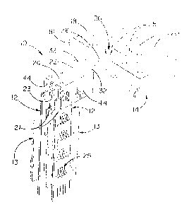
FIGURE 2 is a fragmentary perspective view of a
typical shelf equipped with a new and improved display
hanger incorporating the features of the present inven-
tion.
FIG. 2 is a fragmentary side view of the shelf, the
display hanger and the merchandisers, part of the shelf
being broken away and shown in section.
FIG. 3 is a fragmentary front view of 'the shelf, the
display hanger and the merchandisers, part of the hanger
and one suspended merchandiser being shown in section.
FIG. 4 is a fragmentary cross-section taken substan~
tially along the line 4-4 of FIG. 3.
Detailed Description of the Preferred Embodiments
For purposes of illustration, the invention has been
shown in the drawings as incorporated in a display hanger
10 for supporting strip merchandisers 12 which are par°~
ticularly suited for displaying merchandise 13 in front
of a horizontal shelf 14 having a front edge 16 and
having a horizontal top surface 18 which is formed with
several transversely extending rows of transversely
spaced and vertically extending holes 20. The distance
between transversely spaced holes is typically one inch,
with the holes of adjacent rows being typically offset by
one~half inch.
Each merchandiser 12 is an elongated plastic strip
21 comprising an upper end portion formed with a hole 23
for suspending the merchandiser from the hanger 10 and
formed with a plurality of integral means 25 spaced along
the strip below the hole to releasably grip the merchan-
dise 13 so that customers can easily remove 'the merchan-
2

~~ HA s~ SY
disc for purchase. Reference may be made to the afore-
mentioned Fast patent for a more detailed disclosure of
merchandise holding means generally similar to the means
25.
The display hanger 1U comprises an elongated metal
plate defining a support arm 22 having first and second
end portions 24 and 2fi, respectively, the end portion 26
having integral means for mounting the arm in two of the
vertically extending holes 20 in 'the shelf 14. The
mounting means comprises two parallel prongs 28 formed
integrally with and extending from the arm and, option-
ally, a vertically extending locking hole 30 (best seen
in FIG. 4) located between and spaced forwardly from the
prongs. The arm 22 is formed with embossed ribs 32
extending along the lateral margins of the arm from the
first end portion 24 to the second end portion 26. Each
rib projects upwardly so as to reinforce the arm and
reduce vertical flexing thereof when heavy merchandise is
displayed.
To attach the display hanger 10 to the shelf 14
(FIG. 2), the ends of the prongs 28 are inserted down-
wardly through two adjacent vertically extending holes 20
located inwardly from the edge 16 of the shelf. The
hanger is then maneuvered such that the top of the prongs
are seated against the bottom side 34 of the shelf while
a short section of the arm 22 extending forwardly from
the holes rests on the top surface 18 of the shelf. The
vertically extending hole 30 formed in the arm 22 is
aligned with a hole 20 in the row located forwardly of
the first holes, such 'that an optional locking push pin
3~ can be inserted through the aligned holes. The push
pin is preferably made of plastic and comprises a shank
38 (F'IG. 4) having a head 42 at one end, with axially
spaced and radially extending annular rings 40 pro-
grassing along the shank from the head 'toward the other
end thereof. The annular rings both reduce in diameter
and taper upon progressing away from the head so as to
3

CA 02103285 2003-10-02
reduce the force needed to install the pin. The push pin
is installed by inserting the pin in the aligned holes
such that the annular rings pass through the holes and
the head is seated against the arm 22. The annular ring
in proximity to the head, being of larger diameter than
the holes, engage the bottom 34 of the shelf 14. Thus,
the hanger is securely connected to the shelf.
In accordance with the present invention, the
support arm 22 extends forwardly from the shelf 14 and is
formed with two wings 44 which depend from the lateral
margins of the first end portion 24. Each wing is formed
with an inwardly struck hook 46 (FIG. 3) oriented so as
to suspend the strip merchandiser 12 parallel to the arm,
thereby facing the flow of customers. Moreover, to pro-
vide customers and employees with a quick reference to
merchandise information, the outboard sides of the wings
are substantially flat so that labels (not shown) can be
affixed thereto and viewed from the same direction as the
merchandisers. Each wing preferably is rectangular in
shape.
As shown most clearly in FIG. 3, each support hook
46 is formed with a first segment 48 extending laterally
from the respective wing. A second segment 50 is inte-
grally formed with the first segment of each hook and
extends upwardly and inwardly from the first segment and
toward the arm 22. Each second segment has an upper free
end 52 spaced laterally from the adjacent wing to enable
a merchandiser 12 to be placed on and suspended from the
hook 46. A merchandiser may be suspended from each hook,
such that the two merchandisers face in opposite lateral
directions. An indicia label (not shown) is affixed to
the outboard side of each wing such that it is visible
from a direction parallel to the shelf. The label may be
positioned to cover the opening 54 left in the wing as a
result of striking the hook inwardly therefrom.
From the foregoing, it will be apparent that the
present invention brings to the art a heavy duty display
4

hanger capable of supporting two oppositely facing strip
merchandisers 12 which may be loaded with relatively
heavy merchandise. ~y virtue of the hooks ~6 being
located on the inboard sides of the wings ~4, the out-
s board sides of the wings are left flat and unobstructed
so that indicia labels may be easily placed on'and dis-
played from the wings. The wings and hooks are oriented
such that both the merchandise and the labels are within
the direct sight of customers as they progress down
shopping aisles.

Representative Drawing
A single figure which represents the drawing illustrating the invention.
Administrative Status

2024-08-01:As part of the Next Generation Patents (NGP) transition, the Canadian Patents Database (CPD) now contains a more detailed Event History, which replicates the Event Log of our new back-office solution.

Please note that "Inactive:" events refers to events no longer in use in our new back-office solution.

For a clearer understanding of the status of the application/patent presented on this page, the site Disclaimer , as well as the definitions for Patent , Event History , Maintenance Fee  and Payment History  should be consulted.

Event History

Description Date
Inactive: Expired (new Act pat) 2013-11-17
Inactive: IPC from MCD 2006-03-11
Grant by Issuance 2004-08-03
Inactive: Cover page published 2004-08-02
Inactive: Final fee received 2004-05-19
Pre-grant 2004-05-19
Notice of Allowance is Issued 2003-12-19
Letter Sent 2003-12-19
Notice of Allowance is Issued 2003-12-19
Inactive: Approved for allowance (AFA) 2003-12-01
Amendment Received - Voluntary Amendment 2003-10-02
Inactive: S.30(2) Rules - Examiner requisition 2003-05-02
Amendment Received - Voluntary Amendment 2000-02-03
Inactive: Application prosecuted on TS as of Log entry date 2000-01-11
Letter Sent 2000-01-11
Inactive: Status info is complete as of Log entry date 2000-01-11
All Requirements for Examination Determined Compliant 1999-11-12
Request for Examination Requirements Determined Compliant 1999-11-12
Application Published (Open to Public Inspection) 1995-02-24

Abandonment History

There is no abandonment history.

Maintenance Fee

The last payment was received on 2003-10-20

Note : If the full payment has not been received on or before the date indicated, a further fee may be required which may be one of the following

  • the reinstatement fee;
  • the late payment fee; or
  • additional fee to reverse deemed expiry.

Please refer to the CIPO Patent Fees web page to see all current fee amounts.

Owners on Record

Note: Records showing the ownership history in alphabetical order.

Current Owners on Record
SOUTHERN IMPERIAL, INC.
Past Owners on Record
STANLEY C. VALIULIS
Past Owners that do not appear in the "Owners on Record" listing will appear in other documentation within the application.
Documents

To view selected files, please enter reCAPTCHA code :


To view images, click a link in the Document Description column. To download the documents, select one or more checkboxes in the first column and then click the "Download Selected in PDF format (Zip Archive)" or the "Download Selected as Single PDF" button.

List of published and non-published patent-specific documents on the CPD .

If you have any difficulty accessing content, you can call the Client Service Centre at 1-866-997-1936 or send them an e-mail at CIPO Client Service Centre.


Document
Description 
Date
(yyyy-mm-dd) 
Number of pages   Size of Image (KB) 
Representative drawing 1998-05-11 1 11
Representative drawing 2003-12-02 1 11
Description 2003-10-02 5 198
Claims 2003-10-02 3 103
Abstract 1995-04-08 1 17
Drawings 1995-04-08 1 24
Cover Page 1995-04-08 1 36
Claims 1995-04-08 3 130
Description 1995-04-08 5 229
Cover Page 2004-06-30 2 41
Acknowledgement of Request for Examination 2000-01-11 1 180
Commissioner's Notice - Application Found Allowable 2003-12-19 1 160
Correspondence 2004-05-19 1 30
Fees 1996-10-22 1 72
Fees 1995-10-25 1 69