Sélection de la langue

Search

Sommaire du brevet 2103285 

Énoncé de désistement de responsabilité concernant l'information provenant de tiers

Une partie des informations de ce site Web a été fournie par des sources externes. Le gouvernement du Canada n'assume aucune responsabilité concernant la précision, l'actualité ou la fiabilité des informations fournies par les sources externes. Les utilisateurs qui désirent employer cette information devraient consulter directement la source des informations. Le contenu fourni par les sources externes n'est pas assujetti aux exigences sur les langues officielles, la protection des renseignements personnels et l'accessibilité.

Disponibilité de l'Abrégé et des Revendications

L'apparition de différences dans le texte et l'image des Revendications et de l'Abrégé dépend du moment auquel le document est publié. Les textes des Revendications et de l'Abrégé sont affichés :

  • lorsque la demande peut être examinée par le public;
  • lorsque le brevet est émis (délivrance).
(12) Brevet: (11) CA 2103285
(54) Titre français: DISPOSITIF DE SUSPENSION MUNI D'AILES PORTE-ETIQUETTES ET DE CROCHETS ORIENTABLES
(54) Titre anglais: HEAVY DUTY HANGER ASSEMBLY WITH LABEL WINGS AND ORIENTING HOOKS
Statut: Durée expirée - au-delà du délai suivant l'octroi
Données bibliographiques
(51) Classification internationale des brevets (CIB):
  • A47F 07/00 (2006.01)
  • A47F 05/00 (2006.01)
(72) Inventeurs :
  • VALIULIS, STANLEY C. (Etats-Unis d'Amérique)
(73) Titulaires :
  • SOUTHERN IMPERIAL, INC.
(71) Demandeurs :
  • SOUTHERN IMPERIAL, INC. (Etats-Unis d'Amérique)
(74) Agent: MACRAE & CO.
(74) Co-agent:
(45) Délivré: 2004-08-03
(22) Date de dépôt: 1993-11-17
(41) Mise à la disponibilité du public: 1995-02-24
Requête d'examen: 1999-11-12
Licence disponible: S.O.
Cédé au domaine public: S.O.
(25) Langue des documents déposés: Anglais

Traité de coopération en matière de brevets (PCT): Non

(30) Données de priorité de la demande:
Numéro de la demande Pays / territoire Date
08/109,964 (Etats-Unis d'Amérique) 1993-08-23

Abrégés

Abrégé français

Ensemble de suspension, utilisé pour présenter des marchandises devant une étagère horizontale perforée, incluant une plaque allongée ayant un ancrage de montage pour une fixation à l'étagère, deux ailes pendantes destinées à maintenir des étiquettes, et deux crochets descendant des ailes pour suspendre des présentoirs. Les crochets et les ailes sont orientés de sorte qu'à la fois les présentoirs et les étiquettes soient clairement visibles d'une ligne de vision parallèle à l'étagère, renforçant ainsi les ventes potentielles des marchandises supportées par la suspension.


Abrégé anglais

A hanger assembly, used for displaying merchandise in front of a perforated horizontal shelf, includes an elongated plate having a mounting anchor for attaching to the shelf, two depending wings for holding labels, and two hooks struck out of the wings for suspending display merchandisers. the hooks and the wings are oriented so that both the merchandisers and the labels are clearly visible from a line of sight parallel to the shelf, thereby increasing the potential sales of the merchandise supported from the hanger.

Revendications

Note : Les revendications sont présentées dans la langue officielle dans laquelle elles ont été soumises.


The embodiments of the invention in which an exclu-
sive property or privilege is claimed are defined as
follows:
1. A display hanger for suspending merchandise for-
wardly of a generally horizontal display shelf having a
plurality of vertically extending hole means formed
therein, said hanger comprising a generally horizontal
metal support plate, said plate having first and second
end portions, said first end portion having integral
support means for retaining said hanger in said hole
means, two substantially flat integral wings projecting
downwardly from opposite lateral margins of said plate
adjacent said second end portion for holding indicia
labels, a support hook struck from each of said wings and
projecting inwardly therefrom, each of said hooks having
a first segment extending inwardly from the respective
wing and a second segment formed integrally with said
first segment and projecting upwardly therefrom, each of
said second segments having an upper free end spaced
inwardly from the respective wing to enable merchandise
to be placed on and supported from said hook.
2. A display hanger as described in claim 1, where
said first end portion of said plate includes a ver-
tically extending locking hole, said locking hole being
positioned such that it is axially aligned with one of
said hole means in said shelf when said support means is
retained in other ones of said hole means, and a push pin
projecting through said locking hole and unto said one
hole means to help retain said hanger on said shelf.
3. A display hanger as described in claim 1, where
said support means comprises two parallel prongs formed
integrally with and extending from said plate, said
prongs being parallel to each other such that they align
with two of said hole means, each of said prongs having a
6

downwardly extending step so that a top of each prong
engages a bottom of said shelf and a bottom of said
plate rests on a top of said shelf when said hanger is
installed on said shelf.
4. A display hanger as described in claim 1,
further including two elongated and generally vertical
plastic strips each having an upper end portion and each
having vertically spaced integral means located below
said upper end portion for supporting said merchandise,
and holes formed through the upper end portions of said
strips to enable said strips to be placed on said hooks
and oriented such that both of said strips face in
opposite lateral directions.
5. The combination of (A) two strip merchandisers
and (B) a hanger for suspending said merchandisers for-
wardly of a generally horizontal display shelf having a
plurality of vertically extending hole means formed
therein, each of said strip merchandisers comprising an
elongated and generally vertical plastic strip having an
upper end portion and having vertically spaced integral
means located below said upper end portion for supporting
said merchandise, and holes formed through the upper end
portions of said strips, said hanger comprising a
generally horizontal metal support plate, said plate
having first and second end portions, said first end
portion having integral support means for retaining said
hanger in said hole means, two substantially flat inte-
gral wings projecting downwardly from opposite lateral
margins of said plate adjacent said second end portion
for holding indicia labels, a support hook struck from
each of said wings and projecting inwardly therefrom,
each of said hooks having a first segment extending
inwardly from the respective wing and a second segment
formed integrally with said first segment and projecting
upwardly therefrom, each of said second segments having
7

an upper free end spaced inwardly from the respective
wing to enable said strips to be placed on said hooks and
oriented such that bath of said strips face in opposite
lateral directions.
8~~

Description

Note : Les descriptions sont présentées dans la langue officielle dans laquelle elles ont été soumises.

sJ -. a,y ,s;~ r, ~-
~u ~ ~ ' s".
ca' ~(,i ~'J sJ
Backc~.round of_the Invention
This invention relates to a display hanger and, more
particularly, to a hanger used to suspend merchandise
from a horizontal shelf for viewing by store customers.
Still more particularly, the hanger is adapted to hold
plastic strip merchandisers of the general type disclosed
in Fast United States Patent 4,546,943.
Most conventional methods of supporting plastic
strip merchandisers orient the strip, merchandise
attached thereto, and a corresponding label such that
they face into the customer aisle provided between
columns of shelves. As a result, the vi.sibili~ty of the
merchandise is diminished because the flow of customer
'traffic is perpendicular to the direction in which the
strap merchandisers are facing,
Summary of the Invention
The general aim of the present invention is to pro-
vide a new and improved display hanger which vertically
supports plastic strip merchandisers so that both the
merchandise and indicia labels face the flow of customers
as they pass through store aisles.
A more detailed objective of the invention is to
achieve the foregoing by providing a display hanger com-
prising an elongated plate which mounts to a shelf, and
two depending wings each formed with a hook on its
inbaard side, Each hook terminates in an open end spaced
laterally inwardly from the wing, thereby enabling mer-
ehandise to be placed on and suspended from the hanger
such that it may be easily viecaed from a direction
parallel to the shelf. The depending wings face
laterally so that an indicia label affixed to the out-
board side of each wing may be easily viewed.
These and other objects and advantages of the inven-
tion will become more apparent from the following
1

~r~ ~~~~~z3
detailed description when taken in conjunction with the
accompanying drawings.
Brief Description of the Drawings
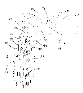
FIGURE 2 is a fragmentary perspective view of a
typical shelf equipped with a new and improved display
hanger incorporating the features of the present inven-
tion.
FIG. 2 is a fragmentary side view of the shelf, the
display hanger and the merchandisers, part of the shelf
being broken away and shown in section.
FIG. 3 is a fragmentary front view of 'the shelf, the
display hanger and the merchandisers, part of the hanger
and one suspended merchandiser being shown in section.
FIG. 4 is a fragmentary cross-section taken substan~
tially along the line 4-4 of FIG. 3.
Detailed Description of the Preferred Embodiments
For purposes of illustration, the invention has been
shown in the drawings as incorporated in a display hanger
10 for supporting strip merchandisers 12 which are par°~
ticularly suited for displaying merchandise 13 in front
of a horizontal shelf 14 having a front edge 16 and
having a horizontal top surface 18 which is formed with
several transversely extending rows of transversely
spaced and vertically extending holes 20. The distance
between transversely spaced holes is typically one inch,
with the holes of adjacent rows being typically offset by
one~half inch.
Each merchandiser 12 is an elongated plastic strip
21 comprising an upper end portion formed with a hole 23
for suspending the merchandiser from the hanger 10 and
formed with a plurality of integral means 25 spaced along
the strip below the hole to releasably grip the merchan-
dise 13 so that customers can easily remove 'the merchan-
2

~~ HA s~ SY
disc for purchase. Reference may be made to the afore-
mentioned Fast patent for a more detailed disclosure of
merchandise holding means generally similar to the means
25.
The display hanger 1U comprises an elongated metal
plate defining a support arm 22 having first and second
end portions 24 and 2fi, respectively, the end portion 26
having integral means for mounting the arm in two of the
vertically extending holes 20 in 'the shelf 14. The
mounting means comprises two parallel prongs 28 formed
integrally with and extending from the arm and, option-
ally, a vertically extending locking hole 30 (best seen
in FIG. 4) located between and spaced forwardly from the
prongs. The arm 22 is formed with embossed ribs 32
extending along the lateral margins of the arm from the
first end portion 24 to the second end portion 26. Each
rib projects upwardly so as to reinforce the arm and
reduce vertical flexing thereof when heavy merchandise is
displayed.
To attach the display hanger 10 to the shelf 14
(FIG. 2), the ends of the prongs 28 are inserted down-
wardly through two adjacent vertically extending holes 20
located inwardly from the edge 16 of the shelf. The
hanger is then maneuvered such that the top of the prongs
are seated against the bottom side 34 of the shelf while
a short section of the arm 22 extending forwardly from
the holes rests on the top surface 18 of the shelf. The
vertically extending hole 30 formed in the arm 22 is
aligned with a hole 20 in the row located forwardly of
the first holes, such 'that an optional locking push pin
3~ can be inserted through the aligned holes. The push
pin is preferably made of plastic and comprises a shank
38 (F'IG. 4) having a head 42 at one end, with axially
spaced and radially extending annular rings 40 pro-
grassing along the shank from the head 'toward the other
end thereof. The annular rings both reduce in diameter
and taper upon progressing away from the head so as to
3

CA 02103285 2003-10-02
reduce the force needed to install the pin. The push pin
is installed by inserting the pin in the aligned holes
such that the annular rings pass through the holes and
the head is seated against the arm 22. The annular ring
in proximity to the head, being of larger diameter than
the holes, engage the bottom 34 of the shelf 14. Thus,
the hanger is securely connected to the shelf.
In accordance with the present invention, the
support arm 22 extends forwardly from the shelf 14 and is
formed with two wings 44 which depend from the lateral
margins of the first end portion 24. Each wing is formed
with an inwardly struck hook 46 (FIG. 3) oriented so as
to suspend the strip merchandiser 12 parallel to the arm,
thereby facing the flow of customers. Moreover, to pro-
vide customers and employees with a quick reference to
merchandise information, the outboard sides of the wings
are substantially flat so that labels (not shown) can be
affixed thereto and viewed from the same direction as the
merchandisers. Each wing preferably is rectangular in
shape.
As shown most clearly in FIG. 3, each support hook
46 is formed with a first segment 48 extending laterally
from the respective wing. A second segment 50 is inte-
grally formed with the first segment of each hook and
extends upwardly and inwardly from the first segment and
toward the arm 22. Each second segment has an upper free
end 52 spaced laterally from the adjacent wing to enable
a merchandiser 12 to be placed on and suspended from the
hook 46. A merchandiser may be suspended from each hook,
such that the two merchandisers face in opposite lateral
directions. An indicia label (not shown) is affixed to
the outboard side of each wing such that it is visible
from a direction parallel to the shelf. The label may be
positioned to cover the opening 54 left in the wing as a
result of striking the hook inwardly therefrom.
From the foregoing, it will be apparent that the
present invention brings to the art a heavy duty display
4

hanger capable of supporting two oppositely facing strip
merchandisers 12 which may be loaded with relatively
heavy merchandise. ~y virtue of the hooks ~6 being
located on the inboard sides of the wings ~4, the out-
s board sides of the wings are left flat and unobstructed
so that indicia labels may be easily placed on'and dis-
played from the wings. The wings and hooks are oriented
such that both the merchandise and the labels are within
the direct sight of customers as they progress down
shopping aisles.

Dessin représentatif
Une figure unique qui représente un dessin illustrant l'invention.
États administratifs

2024-08-01 : Dans le cadre de la transition vers les Brevets de nouvelle génération (BNG), la base de données sur les brevets canadiens (BDBC) contient désormais un Historique d'événement plus détaillé, qui reproduit le Journal des événements de notre nouvelle solution interne.

Veuillez noter que les événements débutant par « Inactive : » se réfèrent à des événements qui ne sont plus utilisés dans notre nouvelle solution interne.

Pour une meilleure compréhension de l'état de la demande ou brevet qui figure sur cette page, la rubrique Mise en garde , et les descriptions de Brevet , Historique d'événement , Taxes périodiques et Historique des paiements devraient être consultées.

Historique d'événement

Description Date
Inactive : Périmé (brevet - nouvelle loi) 2013-11-17
Inactive : CIB de MCD 2006-03-11
Accordé par délivrance 2004-08-03
Inactive : Page couverture publiée 2004-08-02
Inactive : Taxe finale reçue 2004-05-19
Préoctroi 2004-05-19
Un avis d'acceptation est envoyé 2003-12-19
Lettre envoyée 2003-12-19
Un avis d'acceptation est envoyé 2003-12-19
Inactive : Approuvée aux fins d'acceptation (AFA) 2003-12-01
Modification reçue - modification volontaire 2003-10-02
Inactive : Dem. de l'examinateur par.30(2) Règles 2003-05-02
Modification reçue - modification volontaire 2000-02-03
Inactive : Dem. traitée sur TS dès date d'ent. journal 2000-01-11
Lettre envoyée 2000-01-11
Inactive : Renseign. sur l'état - Complets dès date d'ent. journ. 2000-01-11
Toutes les exigences pour l'examen - jugée conforme 1999-11-12
Exigences pour une requête d'examen - jugée conforme 1999-11-12
Demande publiée (accessible au public) 1995-02-24

Historique d'abandonnement

Il n'y a pas d'historique d'abandonnement

Taxes périodiques

Le dernier paiement a été reçu le 2003-10-20

Avis : Si le paiement en totalité n'a pas été reçu au plus tard à la date indiquée, une taxe supplémentaire peut être imposée, soit une des taxes suivantes :

  • taxe de rétablissement ;
  • taxe pour paiement en souffrance ; ou
  • taxe additionnelle pour le renversement d'une péremption réputée.

Les taxes sur les brevets sont ajustées au 1er janvier de chaque année. Les montants ci-dessus sont les montants actuels s'ils sont reçus au plus tard le 31 décembre de l'année en cours.
Veuillez vous référer à la page web des taxes sur les brevets de l'OPIC pour voir tous les montants actuels des taxes.

Historique des taxes

Type de taxes Anniversaire Échéance Date payée
TM (demande, 4e anniv.) - générale 04 1997-11-17 1997-10-22
TM (demande, 5e anniv.) - générale 05 1998-11-17 1998-10-21
TM (demande, 6e anniv.) - générale 06 1999-11-17 1999-10-20
Requête d'examen - générale 1999-11-12
TM (demande, 7e anniv.) - générale 07 2000-11-17 2000-10-20
TM (demande, 8e anniv.) - générale 08 2001-11-19 2001-10-19
TM (demande, 9e anniv.) - générale 09 2002-11-18 2002-10-22
TM (demande, 10e anniv.) - générale 10 2003-11-17 2003-10-20
Taxe finale - générale 2004-05-19
TM (brevet, 11e anniv.) - générale 2004-11-17 2004-10-19
TM (brevet, 12e anniv.) - générale 2005-11-17 2005-10-05
TM (brevet, 13e anniv.) - générale 2006-11-17 2006-10-30
TM (brevet, 14e anniv.) - générale 2007-11-19 2007-10-30
TM (brevet, 15e anniv.) - générale 2008-11-17 2008-10-30
TM (brevet, 16e anniv.) - générale 2009-11-17 2009-10-30
TM (brevet, 17e anniv.) - générale 2010-11-17 2010-11-01
TM (brevet, 18e anniv.) - générale 2011-11-17 2011-10-31
TM (brevet, 19e anniv.) - générale 2012-11-19 2012-10-29
Titulaires au dossier

Les titulaires actuels et antérieures au dossier sont affichés en ordre alphabétique.

Titulaires actuels au dossier
SOUTHERN IMPERIAL, INC.
Titulaires antérieures au dossier
STANLEY C. VALIULIS
Les propriétaires antérieurs qui ne figurent pas dans la liste des « Propriétaires au dossier » apparaîtront dans d'autres documents au dossier.
Documents

Pour visionner les fichiers sélectionnés, entrer le code reCAPTCHA :


Pour visualiser une image, cliquer sur un lien dans la colonne description du document. Pour télécharger l'image (les images), cliquer l'une ou plusieurs cases à cocher dans la première colonne et ensuite cliquer sur le bouton "Télécharger sélection en format PDF (archive Zip)" ou le bouton "Télécharger sélection (en un fichier PDF fusionné)".

Liste des documents de brevet publiés et non publiés sur la BDBC .

Si vous avez des difficultés à accéder au contenu, veuillez communiquer avec le Centre de services à la clientèle au 1-866-997-1936, ou envoyer un courriel au Centre de service à la clientèle de l'OPIC.


Description du
Document 
Date
(aaaa-mm-jj) 
Nombre de pages   Taille de l'image (Ko) 
Dessin représentatif 1998-05-10 1 11
Dessin représentatif 2003-12-01 1 11
Description 2003-10-01 5 198
Revendications 2003-10-01 3 103
Abrégé 1995-04-07 1 17
Dessins 1995-04-07 1 24
Revendications 1995-04-07 3 130
Description 1995-04-07 5 229
Accusé de réception de la requête d'examen 2000-01-10 1 180
Avis du commissaire - Demande jugée acceptable 2003-12-18 1 160
Correspondance 2004-05-18 1 30
Taxes 1996-10-21 1 72
Taxes 1995-10-24 1 69