Note: Descriptions are shown in the official language in which they were submitted.
21 03290
SNAP ON MOWER TRAIL SHIELD
Field of the Invention
This invention relates to a way of mounting
a trail shield to a lawn and garden mower and, more
particularly, to rear discharge walk behind lawn
mowers.
Background of the Invention
Lawn and garden mowers typically have trail
shield along the rear sections of a mowing deck for
usage therewith. Methods of mounting these trail
shields to the mower deck include trapping the upper
edge of the trail shield between a fixed steel bar and
the mower deck for fixed connection thereto, the use
of trailing brackets bolted to the mower deck
capturing the upper edge of the trailing shield,
molding a wire rod into the upper edge of the trail
shield and then pivotally mounting the wire rod to the
mower deck (normally through an auxiliary flange), and
using a number of "O" shaped pieces passed around the
rear axle, such pieces having a lower end which is
bolted to a separate trail shield. Typically in these
units, the upper edge of the trail shield is fixedly
attached to an intermediate part, which intermediate
part is then connected to the rear edge of the mower
deck. U.S. Pat. No. 5,181,371 is representative of a
trail shield.
Objects and summarY of the Invention
It is an object of the present invention to
provide for a stronger trail shield.
It is another object of the present
invention to simplify the construction of a lawn mower
including a trail shield.
2 1 032 90
It is yet another object of the present
invention to strengthen the interconnection between
the trail shield and the mower deck.
It is still another object of the present
invention to utilize the rear axle of the lawn mower
to interconnect a trail shield to a mower deck.
It is a further object of this present
invention to utilize a full length pivoting connection
between the trail shield and the mower deck.
It is still a further object of this present
to strengthen the interconnection between the upper
edge of the trail shield and the mower deck.
Other objects and a more complete
understanding of the present invention may be had by
referring to the drawings.
Brief Description of the Drawinqs
The structure, operation, and advantages of
the presently preferred embodiment of the invention
will become further apparent upon consideration of the
following description taken in conjunction with the
accompanying drawings wherein:
Fig. 1 is a side view, in cross section, of
the trail shield of Fig. 3 taken substantially along
lines 1-1 therein;
Fig. 2 is a modified version of the trail
shield of Fig. 1; and,
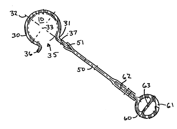
Fig 3 is a rear view of a trail shield for a
walk behind lawn mower incorporating the invention of
the application.
Detailed DescriPtion of the Invention
The trail shield of this invention is
designed for use with a lawn mower having a rod, axle,
or tube 10 somehow connected near the rear of a mower
deck 11. A typical lawn mower is a rear drive lawn
,' X
3 21 03290
mower such as the MTD Model 480. This model is a
single rotary blade, gas engine powered, walk behind
lawn mower having a power driven rear axle. The rear
axle itself extends full length across the width of
the mower deck mounted thereto through two pivoting
swing members 13, 14. The swing members 13, 14 are
steel links approximately four inches in length having
their front sections pivotally mounted to the mower
deck 11 about a swing point with the axle 10
rotatively connected to their trailing ends via
bearing means. A selectable locking height adjustment
arm (not shown) controls the angular pivoting of the
swing members 13 and 14 in respect to the mower deck
11 thus moving the rotating axle 10 upwards and
downwards to adjust the height of cut for the lawn
mower. This particular lawn mower is utilized by way
of example and one skilled in the art would readily
realize that the invention could be adapted for use
with other units including those having fixed
non-rotating rear axles, non-driven rear axles,
differing height rear axles, separated tubular pivot
rods, or otherwise as appropriate for this particular
application.
The invention of this application relates to
an improved trail shield 20. This improved trail
shield includes an attachment section 30, an
intermediate flex section 50, and a trailing portion
60.
The attachment section 30 is designed for
snap over interconnection with a rod, axle, or tube
member, with the added provision that any forces on
the trail shield is passed to approximately the middle
point the attachment section 30. This latter is
accomplished by having the intersection 31 between the
head section 37 (for connection to the intermediate
flex section 50) and the attachment section 30
4 21 03290
occurring substantially congruent with a line 32 drawn
through the contact point of the intermediate flex
section 50 and the use through the axial center 33 of
the attachment section 30. With this design, any
pulling separation force on the trail shield 20 will
be passed to the attachment section 30 directly in
line with the central axis of the attachment section
30. This optimizes the retention strength for the
attachment section 30 in respect to the axle rod or
tube, in this instance the axle 10. Note that the rod
or tube 10 could have a non-circular cross section.
The snap over feature of the trail shield 20
is provided by having an opening 35 in the attachment
section 30. The width of the opening 35 is designed
to be less than the diameter of the rod, axle, or tube
so as to provide a snap over interconnection with the
rod or tubing to be utilized therewith. Preferably,
this opening 35 is located immediately adjacent to the
intersection 31 so as to optimize the amount of force
that the attachment section 30 can withstand before
ultimate separation from the rod, axle, or tube.
Preferably, also, the inside diameter of the
attachment section 30 is sized so as to allow this
section, once installed, to pivot freely about the
tube or rod 10. No screws, bolts, fittings, or clamps
are necessary to install the shield. Once installed,
however, tools such as a screwdriver or knife are
necessary to effect removal. The reason for this is
the comparatively smaller area for the application of
a removal force versus the area for the application of
an installation force.
In the preferred embodiment disclosed, the
axle 10 has a diameter of approximately 0.875". For
this dimension, the width of the opening in the
preferred embodiment is substantially 0.500".
21 03290
A small outwardly extending flange 36
immediately adjacent to the opening 35 is preferable
included. This flange 36 facilitates the installation
of the shield 20 by providing for an inclined lead in
edge for the opening 35 (in combination with other
inclined lead in edge on the other side of the
opening, in this instance the flex section 50). The
angle of this flange 36 in respect to the opening 35
is preferably the same as the angle at the other side
of the opening between the head section 37 and the
attachment section 30. This symmetry would provide
for an equalization of the forces on each side of the
opening 35, thus facilitating installation. In the
preferred embodiment disclosed this angle is
substantially 45. The particular flange 36 disclosed
extends substantially 0.21" outwardly from the main
body of the attachment section 30. The head section
37 extends further.
The particular attachment section 30
disclosed is formed of rigid PVC having a Geon
8700A-296A, Durometer 82 Shore D Min. The attachment
section itself is approximately 0.94" inner diameter
having a wall thickness of 0.075" except at the head
section 37 wherein the thickness increases 0.100".
This thickened head section insures there will be a
minimum of flexing at the intersection 31. This
facilitates the passing of force between the head
section 37 and the rest of the attachment section 30.
The intermediate flex section 50
interconnects the attachment section 30 with the
trailing section 60. The particular intermediate
section 50 disclosed is flexible. This flexing helps
to reduce the non-linear sideward forces which may be
placed on the trailing section 60 due, for example, to
uneven ground terrain.
2t 03290
The particular intermediate section S0
disclosed has a top end Sl which is bonded to the head
section 37 of the attachment section 30 and a bottom
end 52 which is bonded to the later described trailing
section 60. This bonding preferably occurs through
the use of simultaneous extrusion in a die having
three adjacent plastic streams. This facilitates the
manufacture of the trail shield 20 as well as
strengthening the joints relative to other bonding
methods.
The overall length of the preferred
intermediate section S0 between the lower most point
of the attachment section 30 and the upper most point
of the trailing section 60 is approximately 1.74".
This section is approximately 0.09" in width. It is
constructed of vinylex compound Geon 83718 flexible
PVC or equivalent.
The trailing section 60 is designed to
contact the ground at the trailing section of the
mower deck. The particular trailing section 60
disclosed is a circular member 61 having an upwardly
extending flange 62 and a reinforcing intermediate
member 63. As previously discussed, the circular body
member 61 is designed to trail along the ground at the
aft section of the lawn mower. For this reason, a
circular cross section is preferred. The upwardly
extending flange 62 is designed for interconnection
with the intermediate flex section 50. Due to the
fact that ground stresses will be slightly higher at
the lower end of the trail shield, and due to the
desirability of having the lower end continually meet
the ground at an acute angle, the upwardly extending
flange 62 extends for a significant distance from the
round body member 61. In the particular embodiment
disclosed, this extension is substantially 1.14" from
the center line of the body member 61. This extension
;. X
2 1 3290
allows for an extended bond between the intermediate
section 50 and the trailing section 60. This
strengthens this critical connection. The internal
member 63 is designed to strengthen the body member 61
against collapsing forces. This flange is thus
preferably located at approximately 45 angle in
respect to the plane of the ground (see for example
Fig. 1 for an in use position).
In the particular embodiment disclosed, the
trailing section 60 is made of the same rigid PVC as
the attachment section 30. The body member 61 has a
diameter of approximately 0.700" and a wall thickness
of approximately 0.009". The internal member 63 has a
wall section of approximately 0.06".
The trail shield 20 may be modified in
lateral or other cross section so as to meet a
particular application. For example, the particular
trail shield 20 disclosed is designed to be utilized
on a lawn mower having a chain real wheel drive chain
case 17 and a central transmission support 18. For
this reason, cutouts are provided in the trail shield
20 to allow for these additional members. The
combination of cutouts for the pivots, 13, 14 the
height adjustment lever 16, the drive chain case 17,
and the support 18 produces a unique lateral cross
section having particular cutouts for the given
disclosed application (see Fig. 3). These cutouts are
stamped in aggregate in the extrusion of the trail
shield 20 during the process of cutting section of
trail shield off of a multiple length trail shield
extrusion coming from the dies. This process allows
one to utilize given dies for a multiplicity of
applications merely by changing the subsequent
stamping operation. Separately stamping operations
could also be utilized. This post extrusion lateral
cross section modifications allows one to accommodate
21 032~0
a multiplicity of mowers having particular unique
parameters and acceptable trail shield widths in an
expeditious manner via a single extrusion die.
No matter what the embodiment, after
manufacture of the individual trail shield, it is
snapped over the tubing of the lawn mower by hand;
this operation facilitated by the angles of the flange
36 and the head section 37 to the opening 35 plus the
fact that the installer has access to the large
circular diameter section of the attachment section 30
(i.e. a significant easily accessible area for the
application of installation forces). Once installed,
due to the fact that the attachment section 30 can
swivel around the axle 10 in combination with the
flexible properties of the intermediate section 50,
the forces on the attachment section 30 are minimized,
with any forces from the trailing section 60 passed to
the center of the attachment section 30 where they can
be efficiently absorbed. The trail shield 20 is thus
strong and adaptable. The trail shield 20 is also
difficult to remove without tools (i.e. only a minimum
area is accessible for the application of removal
forces).
Although the invention has been described in
its preferred form in particular detail, it is to be
understood that numerous changes can be made without
deviating from the invention as hereinafter claimed.
As an example of this, the applicant shows a modified
trail shield adapted to be used on an axle smaller in
diameter and without either pivoting or drive features
(see Fig. 2). Further, the interconnection between
the various sections 30', 50', and 60' is accomplished
through a bead approximately 0.19" in diameter on
either end of the sections 30 and 60 with
corresponding diameter bead on the ends of the
intermediate section 50'. This device is installed
.
2 1 0 3 2 90
and operates in a manner similar to the first
embodiment.
Therefore, while the invention has been
described in combination with embodiments thereof, it
is evident that many alternatives, modifications, and
variations will be apparent to those skilled in the
art in light of the foregoing description.
Accordingly, it is intended to embrace all such
alternatives, modifications, and variations which fall
within the spirit and scope of the appended claims.