Note: Descriptions are shown in the official language in which they were submitted.
W<> 92/140(W PC'l/(,B~ 3~1
.~ I ~ ) '' (. 1
.) ''L
BUILI)ING ME'rHOD AND AP:PAE~TUS
DE:SC~ rION
Technical Field
This invention concerns methods of buildlng structures, and
arrangements for use in such methods, which are
particularly advantageous when the suhstrate upon which the
structure is to be built is liable to expansion and/or
contraction.
Ba~lvu~ld Art
Ground heave is a well known phenomenon, arising
particularly but not exclusively in clay ~oils, in which
the substrate expands (e.g. in the event of prolonged ra.in
following a long period without rain, or after removal of
a tree from adjacent a structure which upsets the substrate
water balance) exertinq large pressures on any structure
built onto or into the substrate leading to cracking of the
structure foundations and walls and - in the extreme - to
the complete failure of t~e structure.
Clearly it would be possible to avoid this problem by
ansuring that a void is provided beneath the lowermost part
of the structure as it is built into which void the
substrate may move if subject to heave - without
affecting the building thereabove. 5uch a solution is
possible only if the lowermost part of t~e building is pre-
formed since if it is being built '~on-site" it needs to be
supported - at least until it is sufficiently stable to
stand on its own above the substrate.
,,, - ~: : .
-, . ., . , ,. ~. . .
. .
.
.
. .
. . . ~ . .
:. : :.: . .
WO 92/l~ln()~ C-r/~,13~ )023 ~
~ _ " '1,
~ 2 -
To overcome thls problem and permit structures to be built
on substrates in which heave is likely to occur it has heen
proposed to provide a compressible volum~ between the parts
of the structure in contact with the substrate and the
substrate itself (notably the ground ~eams and ground slabs
used in the structure).
One such known pr~posal is to provide a compressible foamed
plastics material (e.g. expanded polystyrene) layers
between the substrate upon which the structure i5 being
built and the ground beams and ground slabs of the
structure. Such a solution adds greatly to the safety of a
structure, when the substrate on whlch it is built heaves,
by reducing by partial absorption the stress transmitted to
1~ the structure. However, the compressibility of the
plastics foams known to us is limited and the material
always transmits a certain amount of loading to the
structure. As a result the thickness of the foamed
plastics layers required are much greater than would be
needed iP a complete void were provided beneath the
structure (up to 2.5 times the thickness). This
exacerbates another disadvantage - ~hat of the foamed
plastics layer compressing under the weight of concrete as
it is poured.
Another known proposal provides a sandwich support
arrangement having wood or fibre boarding mounted on either
side of a central, fibrous paper-like honeycomb. When dry
the central honeycomb section of ~he support arrangement
will support the weight of wet concrete as it is poured,
but when wet its ability so to do is considerably reduced.
Such an arrangement offers advantages over the foamed
plastics layers proposal and the support need be only 10-
15mm deeper than would have been a complete void.
A disadvantage of this proposal, however, is the need to
keep the cerltral ho~eycomb section of the arrangement dry
' ~ , , '
.
,
.
J~ ~ 2 / ~ ~ 2 3 ~
~ ~IJN~ 3
SL~IZ~JP~O~/93 _ 3 _
for i.t to r~tain its strength whilst ;t is supportinc3, for
example, concrete being pourecl to form a ground beam or a
rein~orced concrete ground slab. Thus when using
arrange~ents embodying thi~s propvsal it is now becoming a
common requirement completely -to cover the support
arrangement with a water impermeable sheet - e.g. polythene
- to prevent the central honeycomb section of the
arrangement collapsing under the weiyht of the concrete
being poured (or even, prior to the concrete being poured,
~0 by the weight of hars placed on it to reinforce the
concrete) following a shower of rain - or even from the
effects of moisture in the concrete itself.
Further disadvantages of such a sandwich support
arrangement are that, under certain condi.tions, it can
(like other wood and certain cellulose products) biodegrade
to form methane gas, which i5 dangerous (see 'New Civil
Engineer' of 11th April 1991), and that it can harbour and
promote infsstation and/or dry rot.
Objects of the invention include the provision of methods
o~ building structures and of apparatus and arrangements
for use in such methods which overcome or at least
allev.iate the above-mentioned and/or other problems or
disadvantages of- the prior art.
B~i~f ~ ~y o~ ts o~ th~ Invention
According to a first aspect o~ the invention there is
provid~d a method o~ building a structure on a substrate,
said method including the steps of providin~ on the
substrate a support arrangement capable of adopting a
first, substantially rigid state whil~t the ~tructure i5
being built thereabove, and a subsequen~, second state
per~itting the acc~ ~tion of movement of, and/or forces
35 , in, the subst:rate beneath the structure, said method being
charas~terisll3tl~
- - . :
. ,
: ~ , ........ .
.. . .
,
i~ .'J 2 / ~ ~ ~ 3i~
g Jli~E 19
5~ ~ 20PC~6/1~
by the use of a support arrangem~nt which includes a
rigld surface part and a plurality of container means that
can confine fluid,
by positioning the said container means in mutually
spaced apart relation on the substrate and the said rigid
surface part on the plurality o~ mutually spaced apart
container means so as to be supported thereby,
by confining fluid in said container means such as to
cause the support arrangement to adopt its said
substantially rigicl state and space the rigid sur~ace part
above the substrate to provide a void therebetween,
by forming the structure whilst it is at least in part
supported by the said support arrangement in said
substantially rigid state,
and by providing for the support arrangement to adopt
its said second state by passage of ~luid from the
container means to permit accomodation of movement o~
and/or forces in the substrate beneath.
According to a second aspect o~ this invention there is
provided a support arrangement for temporarily supporting
at least part of a structure on a suhstrat~, the support
arrangement being capable of adopting a ~irst,
substantially rigid state whilst the structurs is being
built thereabove; and a subsequent, second state in which
it does not contribute to support of the s~ructure but
permit~ the accomodation of movement of, and/or forces in,
the substrate,
charact~ris~d in that
the support arrangement comprises a rigid surface part
and a plurality o~ container means to be mutually spi~ced
apart and to support the rigid surface part in ~paced
relation above the substrate below it,
and in hat each of the mutually spaced apart
container means, in the arrangement's first ~tate, is to
confine a fluid therein to a Eirst space and contribute
(via said fluid and the rigid surfac~ part) to the support
of at least part of the structure in spaced relation above
,
'
'. ' '
~ 9 2 / O ~ ~ 3 ~
J~J-, ~ 9 JIJNE 1~93
S~oYAlZO~C~6/9~ _ 5 ~
the substrate and, in the arrangement's second state, is
not to confine the ~luid but be either in a reduced space
or be readily compressible to a reduced space by said
movement and/or forces.
It will be appreciated that if th~ defining wall or walls
o~ the fluid container means is/are of resilient material,
the ~luid container mean~ will collapse resiliently to
occupy a reduced space in the arrangement's second state.
Where the defining wall or walls of the fluid container
means can flex but nevertheless form the ~luid container
means as a self-supporting container, the latter - wh~n no
longer confining the ~luid therein - will be readily
compressible to a reduced space by said movement and/or
lS forces.
Advantageously the container, in the arrangement's second
state, is deformable by said movement and/or forces.
Preferably the said container means are separate from the
said rigid surface part and are provided on the substrate
at discrete locations prior to said rigid surface part
being placed thereon.
In preferred emb~diments of the invention, the discretely
located, ~luid container me~ns space the ~tructure (e.g. a
concrete slab) above the substrat~ such that the entire
area beneath the structure - except ~or the aggrega~e of
the areas occupied by the discrete fluid container means -
is automatically provided at the outset as a void which is
able to accomodate heave of th~ substrate. Any heave
forces tending to be transmitted to the structure via said
discrete ~luid container means, e.g. whilst the latter are
still in their said subs~2ntially rigid condition, can thus
be of a con~iderably reduced ef~ect and can be reduced
still further towards 2ero ~hen the said condition is no
longer maintained, l.e, when the arrangement is in its
~econd stat~.
' - , ' ' -
-
.
g ~ jla ~ItJ~ J ~ I U U ~ ~ ~
E l~g~
sL~12~Pc~6,~, ~ 6 -
Each fluid container means pref~r~bLy comprises, in the
arrangement's said ~'irst st~te, a fluicl tight, fluid filled
container which is sealed su~h as to mainkain a
pressurised, substantially rigid condition but which is
thereafter, in the arrangemerlt's second state, unsealed
enabling it to collapse and/or defor~ should the substrate
therebeneath move.
Preferably, passage of fluid from the container ~eans is by
leakage therefrom.
Advantageously, the fluid is confirled in said con-tainer
means at above atmospheric pressure.
The said at least part of the structure may comprise a
ground beam or a ground slab ~or the structure. It will be
appreciated that, by providing a said support arrangement
between the said at least part of the structure and the
substrate thereunder only whilst the structure is being
built, expansion o~ the substrate (particularly i~ a clay
substrate) may thereafter take place without deleteriously
affecting the structure.
In on~ embodiment, each oP the said container means
comprise~ expansible means, the method being further
characterised in that, to initiate the arrangement's first
state, ~ach said expansible means is expanded to lift the
s~id rigid surface part with respect to the substrate
beneath it, each said expansible means is maintained in
this expanded condition whilst said structure is built and
at least in part supported upon the rigid surface part, and
thereafter ~ach said expansible means is allowed to
contract to render the arrangement into its said second
state and such that a void is formed between the substrate
and the sai.~ at least part o~ the structure built
thereover.
. ~ a 1~ r~, ~ " ;~ t
~7 !nternat~
. . ~ , , ." ~,
.,1 ~ ~j~' ' 1 ~ ~IUII~ 199
s,r~l20r~06/9, - 6cl -
Desirably, in another embod:imen-t, ea~h ~luid container
means may eomprise a cont,ainer that is at least partially
of a degradable material, the method being further
characterised in that each container is sealed such as to
maintain a pressurised, substantially rigid condition in
the arrangement's first state, and the said material is
allowed to degrade such that the container, after time,
becomes unsealed, releasing the fluid therein, whereby the
support arrangement can adopt its second state, and the
container can collapse and/or deform should the substrate
therebelow move.
By collapsing in this ~pecific predictahle and/or
predetermined way, the ~upport arrangement in ef~eck
provides a void between tha substrate and the structure, or
at least part of a structure, built thereover.
According to a third aspect of this invention there is
provided a container for a support arrangement according to
said second aspect of the invention, the container being at
least partially of a degradable material.
Preferably the container compxises a flexible-walled main
body and a ~losure member for the ~ody, said closure member
comprising, as at-least part thereof, a barrier element Por
contact by the intended ~luid contents of the container and
degradable after a generally predictable time o~ contact
with said contents.
According to a ~ourth aspe~t of this inv~ntion there is
provided a closure member for a container according to said
third aspect of the invention, sa1d closure ~ '-or
comprising, a~3 at least part thereo~, a barrier elament for
contact by the intended fluid contents of the container and
deyradable after a generally predictabl~ time o~ contact
with said con-tents.
.
9 2/ 0~ 34
:i 3 ;3 ~ 9 Jl)NE 19~3
5~(~U12~PC05/~3 - 6b
Advantageously the degradabl.e element comprises a
biodegradable or an electrolytically or chemicall~
degradable cap, plug or seal.
In a particularly preferred arrangement the degrada~le
element comprises a magnesium alloy to degrade in a
predictable manner by the effect of, and after a generally
predictable time of contact with, water or a saline
solution wlthin the container.
'
.' ,', ' ''
~,vo 92/l~ I P~ r/G1~9~/fH)~3~1
W 1 (J
A fifth aspect of the invention provides a building method
for at least part of a building, the building method
including the steps of locating a number of planar parts
which together are operable t:o form shuttering for said at
least part of a building in a trench in a substrate with
fluid tight, fluid filled, flexible walled containers
interposed between the said planar parts and the bottom and
side walls of the trench, the containers being maintained
rigid and substantially non-de~ormable whilst the said at
least part of a building is being built and thereafter
being enabled to be collapsed and/or deformed (e.g. thereby
to pro~ide a void that permits movement of the substrate
without deleteriously affecting ~he sai~ at least part o~
a building which has been built).
At least part of the fluid tight, fluid f.illed, flexible
walled containers is degradable and will degrade a~ter
passage of time (falling within a generally predictable
and/or predetermined short time span, e.g. 1 to 3 months)
and after the building has been built. In this way the
fluid within the previously pressurised container is
allowed to escape and the container will collapse under the
upward heave forces (and/or under the weight of the planar
part thereabove) to provide a void that permits the
substrate to heave without deleteriously affecting the said
least part of the building w~ich has been built.
Another aspect of the invention provides a shuttering
arrangement for use in this last-mentioned method and which
comprises a number of linked planar parts which are
locatable in a trench in a substrate to form a framework in
which said at least part of a building may be built, said
planar parts being located in said trench with fluid
filled, f1U;Ld tight, ~lexible-walled containers interposed
between them and the walls of the trench, the containers
being maintained rigid and substantially non~deformable
whilst the said at least part of a building is being made
, ., , ,: : ., - . . : .
: ' ' ' ~ . .' '~ ' ' ' ,
,., ., , , , ,
.. . ...... . . .. . . . ..
:: . : ,
. ,. ~ , .
~0()2/l~ rcr/(~n~2/~l)23
t
~ - 8 -
and thereafter being enabled to be collapsed and/or
deformed to provide a void that permi-ts movement of the
substrate without causing damage to said at least part of
the building which has been built.
Said planar parts may be link~ed by webbing interconnecting
said contalners.
one preferred arrangement embodying the last-mentioned
aspect of the invention comprises a plurality of containers
linked by flexible pockets into which said planar parts may
be passed to form said shuttering.
In all the above aspects of the invention the said fluid
confinable means may be sealed (in the support
arranyement's first state) by a chemically or
electrolytically or biologically degradable closure member
(e.g. a cap, seal or plug); tha latter being such that once
the structure has been built it is possible for the closure
memeber ( cap, seal or plug) to degrade, thereby unsealing
the fluid confinable means whereby the latter no longer
"confines" the fluid but allows the fluid therein to
escape. As a result the fluid confining means can collapse
and/or deform if the substrate begins to heave towards the
structure.
It is envisaged that the fluid used to fill the or each
container may comprise a gas (such as air) or a liquid
(such as water), although it will be appreciated that other
fluids may be used - for example salt water (preferably
carbonated - or otherwise having a gas dissolved therein -
to pressurise the container~.
Brief De~cr:iption of the Dr~win~s
By way of example, embodiments of the invention will now be
described with reference to the accompanying drawings in
which~-
. .
,, . ~. .
':
.. . . ..
WO ')2/1 I~U)~I PC r/(,~3~)2/~ 23~1
a
. 9
Figure 1 schema-tically shows a side view of a ~irst
compressible support arrangement used in a method
of the invention.
Figure 2 is a schematic perspective ~ie~l, to an enlarged
scale, of a deformable container forming part of
the support arrange:ment of Figure 1,
Figure 3 i5 ~ schematic cross sectional view of parts of
one particular form of ~he contalner of Fig 2,
Figure 4 is a scheJnatic cross-~ectional view of another
particular form of the container of Fig 2,
Figure 5 shows schematically at A and B ~ide an plan views
of another support a.rrangement e~bodying the
invention,
Figure 6 is a schematic sectional end view of shuttering
in use and employing elements embodying the
invention, and
Figure 7 shows a modified form of the shuttering shown in
Figure 6 as supplied (at A) and as used (at B).
Description of ~he r ~ s
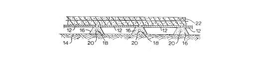
Figure 1 shows a support arrangement, embodying the
invention, to comprise a number of planar parts 12 disposed
alongside one another. In this embodiment, the parts 12
comprise cem~nt bonded particle boards - formed by
compressing and curing a mixture of cement and wood chip
particles - such as are sold by CP Boards Ltd of Manor
Yard, Great Shefford, Berks, RG16 7DZ. The planar parts 12
are supported above a substrate 14 - above which at least
part of a structure is to be built - by a number of sealed,
flexible walled, containers 16 of plastics material which
underlie and support edges of the planar parts 12 as shown.
End walls of each container 16 are provided with apertures
1~. A~ter the container has been filled with water
(preferably salt water) or other fluid, the apertures 18
are closed by a closure member, e.g. a cap, plug or seal
20. A slab 22 of concrete is formed on the planar elements
.. . .
,
.
, . -': ': ' ' .' : ' ~ '
.~ . , . . ., :
.
.
': . '. .... ~. :
WO 92/ l UJ()~l PCI'/(; B'12/0(J23~1
12 - the slab being supported above the substrate by inter
al ia the fluid of the support arrangement.
Each fluid filled container 16 shown in Figure 1 has
generally the form shown in Figure 2, that is to say it
comprises a flexible walled container of plastics material
with an upper wall 24 and a lower wall 26 which run
generally parallel one to lhe other. In use the upper
walls 24 support the planar elements 12 of the support
arrangement and the lower walls 26 rest on the substrate
lq. The distance between the walls 24 and 26 may be any
desired distance, but will normally be in the range of 50
to 150mm. The side walls 28 of the containers 16 can be
parallel or can converge as they extend from the lower
wall 26 to the upper wall 24 as shown. Each contalner may
be provided of indefinite length (say 300mm to 3 metres)
and may have a number of cross walls 30 - each of which is
pierced by an apPrture 18 - prefera~ly spaced 300mm apart.
On site, the or each planar part 12 is supported on a
predetermined array of a number of containers 16, each of
predetermined length, either directly thereon or upon a
narrow bridge plate (of inverted U-shaped cross section)
that extends between and rests upon a pair of containers
16. Alternatively a single, variable length container
having a plurality of cross walls 30 may be cut to length
on site such that two outermo~t cross walls 30 form end
walls 32 for the container. After ~illing the container
with water (or a chemical, e.g. salt, in water solution) or
other fluid, the apertures 18 in the end walls 32 of the
variable length or the ~ixed length containers 16 are then
closed by a closure member tsuch as a cap, plug or seal
member~ as indicated at 20. Each such closure member 20 has
a wall portion that is of, or incorporates, a material
having a substantially predetermined degradation rate such
that it will, with passage of time, and within a generally
predetermined or predictable short period (e.g. having a
:. :
,, , ' . . .
.
.
. ~
wos2/~ t ~ ~J.~ f~C~ )2~)1)23~
specific value in the range of L week to 3 months), degrade
and thereby allow the fluid in the container to escape.
For a container of fixed length only one such cap is
required.
After the concrete of the slab 2~ has cured, say 4-6 weeks
after it is made, the predictably-degrading plugs 20
degrade to an extent removing their sealing effect on the
containers and allowing the fluid within the container l6
to escape. Thereafter container 16 provides or acts as a
void and can collapse due to the weight of the planar
elements 12 (such that a ~urther void is formed immediately
beneath the slab 22 which has been built) and/or due to the
upwards forces thereon from heave of the substrate l4 -
that is to say from the upwards rise of the substrate 14
towards the slab 2~. In other words the support arrangement
ensures that, if there is a movement, it will be contained
within the void(s) and no damage will be done to the slab
22.
Thus the containers 16 act as substantially incompressible
supports for the structure as it is being built but
thereafter collapse providing a void permitting clayheave
or substrata movement towards the slab 22 without any
deleterious effect on the slab itself or the structure
thereabove.
The cap, plug or seal 20 can be of various forms but, in
all the a~oresaid arrangements co~operates with the body of
the container to seal it such that the sealed container is
substantially incompressible, the material of the container
body being such that the container is by comparison readily
~ompressible when it is unsealed.
In 2 preferred arrangement, ea~h container 16 is a bottle
blow-mouldec1 of polyethylene teraphthalate (PET) plastics
material to have a substantially parallelepiped form of
, ' .
.
.
,
WO9~ r/C~ )23
approximate dimensions in the range 150mm x 200-300mm x 50-
150mm and an externally-threaded neck 43 (~igs 3 and 4)
leading to an open mouth, e.g. of about 50mm diameter.
Such bottles can be produced with highly flexible walls of
a thickness less than lmm yet, when filled with water and
sealed by an internally-threaded closure member screwed
onto the bottle's neck and mouth, are substantially rigid
and can withstand an external.ly appl.ied pressure of about
75 lbs/inZ without bursting Ol- being excessively deformed.
In one simple construction (see Fig 3) the closure member
20 comprises a plastics material screw cap which has a
small diameter bore or hole 41 in its bight wall 42 and has
a disc 4~ of a water soluble material, e.g. sodium stearate
(soap), sandwiched between that bight wall ~2 and the mouth
46 of the container 16 to cover - and seal - the hole 41.
Alternatively, as shown in Fig 4, a cylindrical.slug of the
water soluble material, e.g. sodium stearate (soap), can be
wedged into the tubular bore or hole 41 (or a tubular
nozzle or spout protruding axially and outwardly of the
c~p's bight wall 42) so as to seal it. With either
construction the water soluble material is initially
sufficiently impervious as to effect sealing of the
container but in a predictable or predetermined period of
time, e.g. approximately 2 months, will dissolve
sufficiently in the fluid within the bo~tle so as ~o unseal
from the cap and permit subsequent collapse of the
container under h~ave forces.
In another construction, tha cap's tubular bore or hole 41
(or the tubular nozzle or spout protruding axially and
outwardly of the cap's bight wall 42) is fitted with a
metallic in~;ert 45 which, when exposed to fluid within t~e
bottle or container 1&, effects a chemical reaction causing
decomposition of the insert 45. Such devices are
considered very predictable as to the decomposition rate
and it is thought can be produced to degrade predictably
.
, --. , '
- , ,
WO~ PC~'/CT~ )23~1
(into an unsealiny condition) within a day or two of a pre-
specified, short time period (e.g. 7 days, 21 days, 2
months or 3 months).
The metallic insert 45 may comprise a cylindrical slug of
a magnesium alloy - e.g. MABl obtainable from Castex
Products Ltd - that is inserted as a close and tight
sealing fit within the cap's tubular nozzle or spout 48.
After filling the container 16 with water, the cap 20 is
screwed on tightly and the sealed container then placed,
with other similarly sealed containers 16, on the substrate
14 before being covered by one or more planar parts 12. If
desired, salt or another chemical compound, e.g. in a
pervious sachet,,may be inserted into the or each container
16 (prior to or subsequent to its being filled with water)
to promote or assist in the degr~dation process. The
chemical de~radation of the magnesium due to the salt water
(saline solukion) is thought to be as follows:
Mg + 2NaCl = MgClz ~ 2Na
2Na ~ 2H2O = 2NaOH + H2
2NaOH + MgCl2 = Mg(OH~ 2 + 2NaCl
In experiments it has been ~ound that with a metal insert
45 consisting of a 5mm diameter cylindrical slug of said
magnesium alloy, a slug length of approximately 5mm will
chemically de~rade to a cap-open state in about ZO days,
and that a slug length of approximately 3.5mm will
chemically degrade to a cap~open state in about 10 days.
It will be appreclated that due firstly to the limited
quantity of magnesium alloy requixed for each slug 45 -
which provides for the effective collapse of each container
16 by degradation of an element ~ar smaller than the
entirety o~ the container - and due secondly to the
relatively large distances between the discrete containers
16, the very small quantities of hydrogen gas liberated by
the degradation process will be widely dissipated so that
~ .
WO92/l~ cr/~()2/l)~)23~!
~ - 14 -
the risk of any hydrogen-induced fire or exploslon is
minimal -if not zero.
In a particularly pre~erred arrangement, each container 16
is a bottle blow-moulded of polyethylene teraphthalate
(PET) plastics material to have a substantially cylindrical
form of approximately 150mm diameter and a length in the
range 100-300mm, its externally-threaded neck, like the
neck 43 leading to an open mouth, e.g. o~ about 50mm
diameter. As illustrated in F:ig ~, the separately-provided
cap ~or this bottl~ 16 is "over-sized" in that it has an
outer diameter similar to that of the bottle and has an
axial length corresponding su~stantially to the axial
length of the bottle's neck 43 whereby, when the cap is
fully screwed onto the bo~tle, ~he bot~le-plus-cap provides
a generally cylindrical formation o~ subs~antially uniform
diameter throughout its length.
The "over-sized" cap of this particularly preferred
arrangemant can usefully serve as a support for the bottle
- either to contact the substrate or to contact the planar
part 12 thereabove.
The cap 20 may be provided separately. If re~uired, it can
be shrink-wrapped to prevent pre-use attask by atmospheric
moisture. In that case, the wrapping may be arranged such
as to be automatically pierced when the cap 20 is ssrewed
on to the container 16.
~lso, with any o~ the aforesaid arrangements o~ the cap and
bottle, a gas-producing water-soluble chemical compound or
mixture, e.g. in a pervious sachet (optionally the same
sachet containing the salt or a differen~ one), may be
inserted into the or each container 16 - prior to or
subse~uent to its being ~illed with water - to increase the
internal pressure within the container 16 (e.g. to the
order of 15psij so that the container is bet~er able ~o
.
- .
,: ,
~ '
WO')~/l.tl~ r'C'1/(~1~')2/l)lJ23
support the loads thereon, e.g. due to the concr~te and its
associated reinforcements. For example, the gas-produaing
water-soluble chemical compound or mixture may be a mixture
of sodlum bicarbonate and t:artaric acid in powder or
granular form.
In yet another alternative arrangement, the degradation
process may be effected by ground moisture alone and the
containers 16 may be only air--filled.
It is envisaged that other chemically, biologically or
electrolytically degradable devices may be provided in the
closure member 20 including (but not limited to)
constructions employing a molecular sleve or a sol-glass.
It will be appreciated t~lat other variations may be made to
the arrangements described. For example the containers
need not be of the particular form shown and/or described
above, but may be of any desired form for example they
may be cuboid in shape (a plurality of containers being
provided at spaced locations along the length or breadth af
the planar elements as desired). Again, if the containers
are to support part of a structure being built on a piled
foundation then they may be apertured - that is to say
provided as a toroidal s~ructure ~hrough which the pile
support may extend.
For example, as shown in Figs 5a and 5b, the support
arrangement 110 comprises rigid upper and lower planar
parts 112 and 11~ of, for example, cement bonded particle
board. The rigid upper and lower planar parts 112 and 114
are joined ~y a plurality of flexible (e.y. string) ties
116 each of which is ~irmly attached to those planar parts
and is of a desired lengt~ (e.g. between 50 and 100 mm).
Sandwiched between the upper and lower planar parts 112 and
114 are ~our flexible air tight elaments 118 of natural or
synthetic rubber individually and separately connected (or,
-
:' :
wo ')2/1~ 'Cl'/(,l~
as shown, also interconnected) by ~ir supply tubes or lines
120 coupling the support arrangement 110 to an air supply
source (for example a compressor) shown dia~ramaticall~ at
122. The elements 118 may simply be positioned between the
planar parts as shown or be fixed in the positions shown in
any suitable way (e.g. by an appropriate adhesive).
It will be appreciated that when air under pressure is
supplied to the tubes or lines 120 from the source 122, th~
elements 118 will expand and push apart the pla~ar parts
112 and 114 up to an amount dete.rmined by the length of the
flexible ties 116.
The elements 118 which are provided between the planar
parts 112 and 114 may comprise single bag formations or,
preferably and as indicated in Figure 5b, be provided as
toroidal or ring structures.
The upper and lower planar parts 112,114 may alternatively
be of any suitable wood, fibre or plastics material and in
any event, may be sized to fit standardised building
elements - for example ground beams -- in which case the
plana~ parts will ~e provided as single element sheets
approximately 2000 x 40mm.
~5
The support arrangement 110 may be of any desired size
and may readily be adapted ~o different site requirements
by cutting the cement bonded particle boards as required -
making use of more or fewer elements 118 as needed. With
cement bonded particle boards $ft by 4ft (2500mm x 1250mm)
in length and breadth, each element 118 contacting the
planar parts 112 and 114 has an area of contact, when fully
inflated, of approximately lft2 (O.lm2' The thickness of
th~ cement bonded particle ~oards may be selected - to suit
site requirements - from the range of thicknesses available
(e.g. from 6mm - 40mm).
., ' ~ . : -
'
WOs~ PCI/(,~2/0~)23
- 17 -
The air lines 120 coupling the elements 118 to the air
supply 122 may include suitable valving (e.g. Schroder
valves) enabling the air supply source 12~ to be decoupled
from the lines as desired.
As illustrated in Fig 5a the air supply lines 122 fe~d to
each of the elements 118 by passing in through the side of
the support arrangement 110 - that is to say between the
two planar parts 112 and 114. It is envisaged that the
lo arrangement descri~ed may be modified b~ providing that the
air supply lines pass to the elements 11~ directly through
the planar parts to which they are attached (for example
through planar part 112 or planar part 114).
In an alternative support arrangement (not shown), the two
planar parts 112,114 are significantly smaller than as
shown in Figure 5, e.g. being now each approximately lft2
(O.lm2), a single flexible element between them being
substantially the same as the element 118 described with
reference to Fiyure 5. In this modification the air supply
line 120 to the flexible element 118 (tha~ is located
between and adhesively attached to the planar par~s 112 and
114) extends through the uppermost planar part 112. As
before, ties 116 are provided to limit separation of the
parts 112 and 114.
In building a structure with the support arran~ements 110,
the latter are provided along the ~round (or substrate) and
the elements 118 are then inflated by compressor 122 to
enable the upper planar part 112 to provide a
susbstantially rigid support, raised from the ground, for
the conrrete that is poured thereon (e.g. to form a ground
beam or ground slab).
The su~port given by the inflated support arrangements 110
beneath the concrete ground slab or beam is sufficient to
.': ' ' ; "
?
WO ')~ Pcr/~ )2/~)~t~34
q ~
support the lat-ter whilst the concrete cur~s and the
structure becomes self supporting.
It will be appreciated that whilst the support arrangements
110 are maintained in their inflated state, the structure
is held clear of the ground by an amount equal to the
thickness (or height) of the inflated support arrangements
110 .
Once the concrete of the structure has cured sufficiently
for it to be self support1ny, the compressor is
disconnected Erom the air supply lines - or the valve(s) in
those lines are opened - such that the air in the
expansible means of the support arrangements 110 is
released. With the reduction in air pressure the planar
parts of the arrangements can move ~owards one another and
voids can be established beneath the ground slab or beam
and into which the substrate may expand without bearing
upon and damaging the fabric of the structure built
thereon.
In still another modification, the compressor 122 is
omitted but the lines 120 are retained to serve as flexi~le
fluid conduits to the elements 118. Prior to superimposing
any concrete or other load upon the planar part 112, the
containers 118 are filled with wat.er or other liquid
(optionally under pressure, e.g. by a soluble gas
carbonated water being most suitable) and the tubes or
lines 120 then sealed - optionally by a degradable plug,
cap or seal. The container is thus ~ubstantially
inco~pressible and, via the liquid therein, will support
the weignt of the planar part 112 and the concrete to be
poured thereon.
once the CGnCrete of the structure has cured, the sealed
ends of the tu~es may be ruptured - for example cut through
where they project through at ground level. Alternatively
. ,. . - :
' '~ ' '' ' ,
. : . ~ ,
.
. . .
.
~V(3')'/l.~ t,, ,~ 'Cr/C~')2/~)~)23
-- 19 --
the degradable seal can be allowed to degrade until the
fluid can emanate from the co,ntainers 118.
It will be seen that should the substrate thereafter heave
the containers 118 will be compressed and their walls will
deform - there being no fluid pressure in the eontainers to
maintain them in their original form - and any residual
fluid remaining in the contai;ners 118 will be expelled.
Thus the containers 118 act as substantially incompressible
supports for the st.ructure as it is being built but
thereaf~er absorb or accomodate clayheave or substrate
movement towards the structure and prevent such movement
having a deleterious effect on the structure thereabove.
It will be appreciated that the lo~er rigid planar part 114
may be omitted in certain cases, e.g. where the substrate
contains no sharp protru5ions and/or where the lower
surface o~ the or each container 118 is protected and/or is
of a thicker material.
Figure 6 shows an embodiment of the invention in use for
the formation of a ground beam 50, including reinforcing
rods 52, in a tr2nch 54. In accordance with this
embodiment of the invention, planar parts 56 are provided
beneath and -to each side of the ground beam 50 which is
being built, and these planar parts are space~ from the
sides of the trench by fluid tight containers 5~ and from
the bottom of the trench by fluid tight containers 60.
Each container 58 and 60 may be, if desired, in substance
the same as that shown in Figure 2, 3, 4 or 5 and be
provided with a similar biodegradable or a similar
chemically or el2ctrolytically degradable cap, seal or
plugO It wi:Ll be appreciated that the containers 60 serve
to permit the acco ~dation of movement of, and/or forces
in, the sub~trate's region below the finished beam, whereas
'
. .
W~ 92/1~100~ C~r/(,l~9~ ()23~l
- 20 -
the containers 58 at the sides of the beam serve to permit
the accomodation of movement of, and/or forces in, the
regions of the substrate beside the finished beam.
In the arrangement of Figure 6 the side planar parts 56 may
be freely supported in the trench - resting against the
containers 58 at the side of the trench - or be fixed to
those containers in any suitable way, such as for example,
by means of a suitable adhesive such as Evostick.
AJ1 alternative shuttering arrangement which is shown in
Figure 7 may however be used. This alternative shuttering
arrangement comprises three flexihle plastics pocket
members 80, 82 and 8~ interconnec~ed by flexible plastics
webbing parts 86. One surface of each of ~he pocket members
80, 82 and 84 carries thereon ~ has formed integrally
therewith - a series of containers 8~, 90 and 92 as shown.
The containers 88, 90 and 92 which are shown in Figure 7
simply comprise fLexible walled plastics containers each in
substance the same as that shown in Figure 2, 3, 4 or 5 and
provided with a similar biodegradable or a similar
chemically or electrolytically degradable cap, seal or
plug. It will be appreciated that the containers 90 serve
to permit the accomodation of movement of, and/or forces
in, the substrate's region below the finish~d beam, whereas
the containers ~8 and 92 at the sides of the beam ~erve to
permit the accomodation of movement of, and~or forces in,
the regions of the substrate beside the finished beam.
In order to use the shuttering arrangement which is shown
in Figure 7 a planar part or member ~6 is placed in each of
the pockets 80, 82 and 84. I'he shuttering arrangement is
then placed in a pre-dug trench with the containers 90 on
the base of the trench and the containers 88 and g2 aligned
with the sides of the trench. The containers ~8 and 92 are
fluid filled under pressure and then sealed.
.
: .. . - :
- .:
.. . . .
': ~ . ' . :
': ~
w092/~ ! f~c-r/~ )23~
The concrete for forming -the ground beam or o-ther
structural element to be formed by the shuttering is then
poured and once it has rured the biode~radable or-
~hemically or electrolytically d~gradable caps, seals or
plugs degrade unsealing the containers and allowing the
fluid in the containers ko lescape and the containers to
collapse.
It is thought the shuttering arrangment shown in Figure 7,
provides a ready and ef~icacious way of speedily allowing
shuttering to be provided in a trench in which a ground
beam is to be formed.
In an alternative arran~ement, the containers 88, 90 and 92
need not be formed integrally with the pocket members 80,
82 and 84, but can be separate, individual containers (e.g.
as in Fig 2) located in their place.
With the arrangement shown in each of the above Figures the
fluid used to fill the containers and keep them in a rigid
condition ~hilst a structure is built thereabove may be any
suitable fluid - for example gas (e.g. air) or liquid (e.g.
water) or a gas-pr~ssurised li~uid (e.g. carbonated water).
It is possible for the fluid which is in the containers
which acts to make them rigid and the support arrangements
capable of ~upporting the building (or part thereof)
thereover to be provided at atmospheric pressure or at an
overpressure if desired.
Although, as described, the planar parts which are used in
the various arrangements embodying the inven~ion are of
cement bonded particle board, it will be appreciated that
any other suitably rigid boarding may be used fo.r example
plyboard and/or chipboard.
~ppli~abilitv o~ ts of ~he Invention
~ ', ' ' .
WO ')~/14(~/)'1 P(-r/~;l3s~ )23Ll
. ~3'~ 22 -
It will be apparent that each of the abo~e~described
embodiments of the invention provides a support arrangement
disposed between a substrate and at least part of a
structure whilst the latter is being built, the support
arrangement comprising at least one container which, whilst
said at least part of the structure is being built, is
filled with a fluid (either a liquid - e.g. water, or a gas
- e.g. air, or a gas-pressurised liquid - e.g. carbonated
water) and sealed or otherwise closed such as to be
substantially rigid and/or relatively non-compressible when
pressurised - by the downward load of the strueture - but
which, after the concrete has set, is unsealed or opened
such that the interior and exterior of the container are in
communication with one another to provide the conditions
whereby the container i5 comparatively deformable and/or
compressible - e.g. by the upward forces due to heave.
It will be appreciated that each of the above~described
and/or illustrated embodiments of the invention provides a
method of building a structure on a substrate and which
comprises the steps of providing on the substrate a support
arrangement which, whilst the structure is being built, is
~aintained in a rigid condition operable to support the
structure or at least parts thereof above the substrate and
which thereafter is not so maintained.
It is believed that the methods and arrangements above
described are particularly effective in meeting the
clayheave problem encountered in the building industry and
in practical terms provide a void beneath a structure built
on substrate likely to be ef~ective to prevent any heave
which might occur from adversely affecting the ~ructure
built thereon.
Other modifi.cations and embodiments of the invention will
he readily apparent to those skilled in this art. A11 such
modificatio~s and embodiments are to be deemed within the
. . - - - - - . - - , .
" , ' ' '
'.' : .' . . ' ~ ~ '
WO92/14004 ~1 ~ 3 ~ 6 ~ P(T/GB92/002
ambit and scope of the invention, and the invention is not
to be deemed limited to the particular embodiment(s)
hereinbefore described which may be varied in construction
and detail without departing from the scope of the patent
monopoly hereby sought.
- .... . i . " ,, ~ : , , " ,
. .. .. . . _ . . = .. .. ~ . . . . .. .. . . . . ... .
, ~
.,.
.
: . c
",
,
. . . ,
;,
: ' ,.~ ,, ,,.......... . ' :
'
"~..,