Note: Descriptions are shown in the official language in which they were submitted.
~ t~ ~ fi,~
SPECIFI~ATION
~I~LE OF INVE~InN
5A coupling and ~,ethod ~or folding back a pipe end
using for it and its apparatus
10The present invention relates to a coupling ~ade
of synthetîc resin used for piping system transferrin~
poisonous fluid of hi~h temperature and high pressure
in a Pield of so-called high technology such as mainly
semiconductor production, and ~ethod for manufacturing
a pipe used ~or this coupling and its manufac-turing
apparatus.
As a coupling's mechanis~ of plastic pipe, various
tight sealing structures using of a tight sealing taper
screw and ferule and others are known.
20However, for instance, in fluoric resins such as
TFE(polytetra~luoroethylene), PFA(copolymer of
polytetrafluoroethylene and perfluoroalkylvinylether),
FEP~copolymer of polytetrafluoropropylene) and the
like, in accordance with their characteristlcs,
poisonous materials and the like of high temperature
and high pressure are manr in fluid used for that~ and
a leahage of fluid are produced which occurs ~y causes
'.
. , ~
, . , , . . , - .
'' ' ''
. , : . . . :
.. .. . .
: . ' ' '' ' ~ '. '' ~ : .
' .' ' . ' '. - ' ~ ' . ' :'
of repeating of expansion and contraction due to heat
cycle and generation of creeping and the like.
This is because ~ainly fine gaps are produced
ca~lsing fron~ above factors to a joinirlg portion, And a
prevention fox this is verY difficult. ~herefore, in
conv~ntional couplings and in those k:inds, a using in
condition at belo~ about temperature of 120 degrees in
Centigrade and pressure of 2K~/c of fluid is inevitably
done.
In accordance with the coupling of the present
invention, front end portion of resin pipe folded bac~s
and ormed in U-shape is coupled to an inner annular
portion of tightenin~ means, a folded portion of -the
resin pipe positioned at concave portion of inner
annular portion, îts U-shaped botto~ is closely
contacted and fixed by an end edge of the inner annular
portion and a curved groove of stopper portion
according to the screw-coupling of the tightening ~eans
and a coupling's main body, and a protruded strip band
~0 strengthens a close contaGt of couplin~'s maill ~odY
inner sur~ace and a concave outer circu~Eerential
surface of resin pipe folded back portion and at the
sa~e ti~le, a lip seal ~akes a close contacting degree
oE inner surface of the coupling ~ain bGdy and an inner
circu~ferential surface of the inner annular portion to
be fir~ and secure, so that a coupling for a pipe of
resin of very high in reliability esp~cially flu~rine
-- 2
'''
resin can be realized without producing any proble~ of
leakage and the like even in allowable li~it range
further above the te~perature condition and pressure
condition of fluid in conventional coupling.
And yet, one which ~ay be citecl as a requisite
condition for above described couplin~ is a structure
which folded back a pipe opening end to outer side.
However~ to ~ake a front end of fluorine resin pipe and
the like to be si~ply, exactly and rapidly folded back
~ith ~eeting to joining condition is very difficult.
Hereto~ore) although it ~ight have been thought
that to fold back a front end of resin pipe toward
outside at nor~al te~perature at-ld the like was
i~possibleJ a technique Eor folding back an end portion
lS of resin pipe was almost nothing.
Therefore, an inventor of this application has
researched and developed a method for foldin~ back an
end of opening of resin pipe and apparatus used for
this folding back ~ethod co~prising a process or
making an annular body to outer circu~ference of a pipe
having a core ~aterial at inner hollow in compliance
with require~ent, and a process for continuing to press
the pipe opening end to axial direction of the pipe
with expanding to out~ard, and with outwardly expandin~
~5 the front end by skillfully utilizin~ a characteristic~
particularly elasticity of the resin and simultaneously
folding back the pipe opening end naturally at certain
-- 3 --
.
- : ' , '.
. ~
. . : . ' . -
J ~
ti~e point, and inserting the pipe openin~ end folded
back to outer circu~ference o aforesaid annular body,
in a process of peripheral technigLle development of
afore~entioned joining str~cture.
~UM~ARY OF THE XNVE~TIQN
The coupling in accordance with the present
invention comprises a nut shaped tightening means
having an outer annular portion and an inner annular
portion, and a coupling's nain body which has a stopper
portion at inner circumferential surface and
si~ultaneously sorew-coupled ~etween said ou-ter annular
portion of the tightening means and the inner annular
portion, and holding by pressing a folded back portion
of a resin pipe between the stopper portion and an end
edge of said inner annular portion; and said tightening
means for~ing a threaded portion at inner
circumferential surface of the outer annular portion
and at the same time providing a lip seal closely
oontactin~ to inner surface of the coupling's nain bod~
around this concave portion end, and said coupling's
main body forming a threaded portion sorew-coupling to
the threadcd portion of said outer annular portion a-t
the outer circumferential surface and on the other
hand9. for~ing a taper portion gradually decreasing a
diameter from the openin~ portion and a straight
- 4
, ~ .
~,3t~ 3
portion continuing to this at inner circu~fe~ential
sur~ace and simultaneously for~ing a groove portion at
a portion abutting with ~olded back apex portion of the
resill pipe in said stopper portion, and urther a
protruded strip band for coupling ~ore fir~ly ~ith this
by abutting to the folded back portion of the resin
pipe is provided around the circu~ferential surface of
said concave portion in the inner annular portion of
nut.
The ~ethod ~or ~olding back a pipe openin~ end
disclosed in this invention comprises:
~ a~ a process for ~ixing an annular body to outer
circumference of pipe having a core material at inner
hollow in ccmpliance with the requirement,
~b) a process ~or outwardly expanding the pipe
opening end and simultaneously pressing to axial
direction of the pipe, and
(c) a process for folding back a pipe opening end
~ade oP material having an elasticit~ by c~ntinuing
said pressing, and inserting the folded ~ack pipe
opening end to the outer circuloference of sa:id annular
body.
And, the apparatus used ~or aforementioned folding
back ~ethod co~prises:
a clamping ~eans of pipe, a bending means, and a
driving ~eans o~ these; and said cla~ping means
includlng a oore materi~1 to be inserted into interior
. : . , ' ~ . : ,
of the pipe in co~pliance with the requirement and a
tightening ~echanis~ for pressing the pipe to radial
direction, and said bending means for pressing the
opening end of the pipe to axial direction of the pipe
by the driving means including a ~ain body portion, and
a guiding portion for folding back the pipe opening end
with outwardly expandi.ng to axial direction
accompanying with a pressing action toward the pipe
axis direction of the ~ain body portion with contacting
to entire circumference of the pipe opening end. And~
in this apparatus, said guidin~ portion includes a
conically protruded portion and a curved surface groove
formed around this, and -further it is characteriæed by
co~prising a position determining means ~or deter~ining
each correlative position of folded portion in the core
material and the annular body and the pipe.
Moreover, in this invention, ~ollowing method for
folding back a pipe opening end is also disclosed.
A method ~or folding back an opening end of resin
pipe co~prising processes of :
(A) a process for inserting the conically
protruded portion of the guiding portion provided with
the conically protruded portion and a curved surface
groove for~ed around this and simultaneously advancing
with rotating the ~uiding portion, and
(B) a process for folding back the pipe opening
end by continuing the advancement and rotation of sald
J 3 ~
guiding portion, and
a ~ethod for foldin~ back an openin~ end of resin
pipe comprising: :
~ C) a pro~ess Por fixing an annular body to a
circu~ference of the pipe,
(D) a process for inserting said conically
protruded portion of a guiding portion provided ~ith
the conically protruded portion and a curved surface
groove formed with this and si~ultaneously advanoing
with rotating the guiding portion, and
(E~ a process Eor folding back the pipe opening
end by cont.inuing the advancing with rotating o~ said
guiding portion, and inserting the pipe opening end
folded back to a circu~erence o~ said annular body.
And, the apparatus used for this folding back
~ethod co~prises a cla~ping ~eans ~or supporting the
pipe and a bending means~ and saià cla~ping ~eans
includes a tightening mechanis~ for pressing the pipe
to radial direction, and said bending means includes a
guiding portion ~or advancing with rotating by abutting
to the pipe opening end, a rotational driving mechanism
for rotating the guiding portion, and a reciprocating
~ecbanis~ for advancing and retreating the guiding
portion to a pipe axis direction, and it is
~5 characterized in -that it is made to fold ~ack the pipe
opening end to axial direction with outwardly expandlng
i-. And in this apparatus, said guidin~ portlon l~ay
.
~e provided with a conically protruded portion alld
curved surfaGe groove for~ed around this.
~.IEE D~SCRIPTIQN OF T~E DRAWIN~S
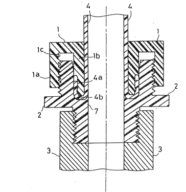
FIG.1 i5 a cro~s sectional view showing a ~'irst
embodi~ent in,accordance with clai~ 1 and claim 2 o~
the invention,
FIG.2 is a ~agnified vi.ew of an end surface of cut . '
lO portion o~ a tightening ~eans in FIG.1, ,''
FIG.3 is a ~agni~ied view o~ an end sur~a~e o~ cut
portion of a coupling's ~ain body'in FIG.1~
FIG.4 is cross sectional view showing a second
e~bodlment of the invention in accordance with clailn 1
to 2,
FIG.S is a side view showing an e~bodi~ent in
accordance ~ith clai~ 5,
FIG.6 is a cross sectional view showing a relation
of position o~ annular bocly and the pipe in clai~ 3,
FIG.7 is a cross sectional view showing an action
of position deter~ining ~eans(inserting means) in clai~
7,
FIG.8 is a cross sectional view showing an
operation of a'bending means in claim 5,
: ,25 FIG.9 is a cross sectional view showing an
operat,ion of a bendin~ ~eans in clai~ 5,
FIG.lQ is a cross sectional view showing an
-- ~ _
.. . . .
. .: . , : . , :
.:
~ c3
operation Oe a bending means in clai~ 5,
FIG.11 is a cross sectional view showing another
embodi~ent o~ annular body in clai~ 5,
FIG.12 and FIG.13 are a cross sectional views
respectively showing a case folded bacls the opening end
of the pipe. without annular body,
FIG.14 is a cross sectional view showing another
embodi~enk of the bending means,
FIG.15 is a side cross sectional view showing a
~irst e~bodiment of claim 10,
FIG.16 is a side cross sectional view showing a
second embodiment o~` claim 10,
FIG.17 and FIG.18(A),(B) are diagra~s showing
exa~ples o~ ~olding back process of the pipe opening
end in accordance with claim 8 or clai~ 9.
5~ b~RIe~ T~ Y~E~m ~
The enbodiments o~ the present invention will be
described in more detail with reference to the
acco~panying drawings. FIG.l to FIG.3 are diagrams
showing a ~irst e~bodilrlent of the invention in
accordance ~ith clai~ 1 to clai~ 2.
In the drawings, a re~erence nu~eral symbol 1 is a
~5 cap-like nut or bag-like nut as a tightening means made
of ~luoric resin ~or~ing a cylindrical shape having an
outer annular portion la and an inner annular portion
.: '
- .
.. . .
.
.. . .. . . . . . .
.
~ ' ' " "' " ' ~" " ' ' '
.
~ ~J~3$-~
lb, and a threaded portion lc is for~ed to an inner
circu~ferential surface of the outer annular portion.
A reference numeral symbol 2 is a coupling's ~ain body
m~d~ of ~luoric resin for~ing a cylindrical shape
coupling in screwing ~anner to the tightening ~eans,
and which has a t.aper portion 2a gradually deereasing
in diameter from the openin~ portion and a straight
portion 2b continuing to this in the inner surface, and
formed with a stopper portion 7 at adjacent of ter~inal
end o~ this straight portion 2b and on the other hand,
a thrèaded portion 2c to be screw-coupled with said
threaded portion lc is for~ed at the outer surface. A
re~erence nu~eral sy~bol 4 is a fluoric resin pipe, and
a U-shaped folded hack portion 4a is formed at its
~ront endJ and an apex portion 4b of the folded back
portion 4a is inserted tc a hereinafter described
curved surface groove 7a in the coupling's main body ~.
Further, a reference numeral sy~bol 3 is a pu~p fixed
by screw-coupling the coupling's ~ain bodY 2.
20FIG.3 is a magnified view of an end surface of cut
portion of the coupling's Inain ~ody 2, and as sho~n in
the drawings, a curved surface groove 7a is ~ormed at
bottom of the stopper portion 7 and which is made to be
coupled with said apex portion 4~.
25Next, asse~bling sequence o~ the coupling in
accordanGe with this em~odi~ent will be described
hereinafter. Firstly, the fluoric resin pipe 4 folded
- lU -
.
~.'' i J ~
back in U-shape with front end is passed to the
tightening ~eans 1, and the apex portion 4~ of the
~olded back portion ~la of the 2iPe 4 is insçrted to the
curved surface groove 7a in the coupling s main body 2.
Successively, a nut 1 is scre~-coupled to the
coupling's main body 2. The nut 1 descends down in
response to the advance~ent of the screw-col}pling, but
since a lip seal 5 protruded a little to sideward is
Eortned with a taper portion 2a, and it descends
gradually without being caught to the inner surface o~
the coupling's ~ain body.
On the other hand, as the descending of the
tightening ~eans 1, the inner annular portion lb
advances to a gap o~ the U-shaped folded back portion
o~ the pipe 4, and completely cuts off a leakage of
~luid fro~ interior of the pipe 4.
The folded back portion 4a o~ the pipe 4 is
positioned at a concave portion 8 o~ the inner annular
portion lb, and the ~olded back portion 4a is fir~ly
2~ contacted to wall surface of the concave portion 8 and
the inner sur~ace o~ the coupling's ~a~n bodY 2. And,
said lip seal 5 is also ~ir~l~ contacted to the inncr
circu~ferential sur~ace o~ the coupling's ~ain body 2J
and ~.he leakage to an outside o~ this coupling becomes
co~pletely prevented even iE supposing that there would
be any leakage between the apex portion 4h and the
curved sur~ace groova 7a.
-- 11 --
, . :. . .
. . .
.
Moreover, the ~olding back of fron-t end of the
fluoric resin pipe 4 is done by using an exclusive
usin~ tool, but in case that thiclsness of the pipe is
large, c>r i~ Gil:ie that the folding ba~}. i5 cli-E:Ficul~ a:~:
in ~ultiple layer pipe which is ~or~ed ~ith PFA in the
inner side and PE in the outer side or a suspended
bridge polyethylene in the inner sicle and a eo~mon
polyethylene in the outer side~ the ~olding back is
readily possible when ~or~ing two layers or a plurality
layer3 by making deep Cll~ notches(not sho~n~ o:f
circu~erenti~l shape to ~ront end surface.
FIG.4 is a diagra~ showin~ a second embodi~ent o~
this invention in accordance with clai~ 1 to 2
In this embodiment, the front end portion of the
pipe 4 is folded back in a state to roll up to outside
as shown in the ~ra~ing. ~ndJ this circularly shaped
Po'lded ba~k portion is made to be held by pressin~ b~
an end portion o~ the inner annular porti~n lb and the
apex portion ~b. '~he other structures are sam~ ~5
a~orementioned embodi~ent.
The present invention, by the construction and
op~ration as de~cribed ~boveJ can completely prevent a
leakage by a creeping pheno~enon which is a great
shortco~ing included uith conventional resin couplin~
~S and further a connection o~ the ~'luoric resin pipe
which has not been found out in si~ple and effective
joining means hereto~'ore can be ver~ si~ply exec~l-ted.
- 12 -
.' ~ ' ' :
1~ ~ S~ LA?L ~
FIG.5 is a cliagram shc,wing a struct.ure c,P the
folding back apparatus in accordance ~i.th claim 5 and
~. In the drawin~, a reference nunJera.l symbol 21 is a
hending means, and a reference numeral s~bol 22 is a
driving source for pressing the bencling means 21 to
axial direction of the resin pipe ~6 through a
reciprocating piston rod 2~a. The bendin~ neans 21
consists of a cylindrically shaped ~ain body 21a and a
guiclin~ portion provided at bottom side q~ this as
shown in FIG.8, and this guiding portion consists of a
conically protrucled portion 21h formed at cel1ter of
s~id hottom surface ancl a curved sur:eace groove ~lc
aro~nd this cir~umference. A diameter of circular
apex portion of the conically protr-lded portion Zlb is
nade slightlY smaller than a diameter o~ the pipe 2G,
and a side surface of the conically protruded portion
21b and t.he curved sorface groove 21c Eorm a continuous
surface, and an openlng end of the pipe ~6 is outwardly
expanded as being ~uided to aforementioned continuous
surface as described hereinaPter and simultaneously, at
a time point that an angle for an axial direction of
the pipe of a portion becoming outwardly expanding has
'c)eGome biggerJ a phenomenon bec:omes produced in which
it is left from surface of the curved surface groove
2~ 21c by an elasticity of pipe ~ formin~ resin and just
as a contraction i.s started to radial direction and
naturally folded back. Further, a connection o~ main
- 13 -
- . : : ~ , - ,
. ., , ~ , - : . : :: : .
. ~ . . . ..
3 ~
body portion 21a of the bending ~eans 21 and the piston
rod 22a is done by a sorew-coupling ~eans. Moreover,
the resin pipe 26 made of materials of large in
elasticity memory such as polytetrafluoroethylene)
copolymer with perfluoroalkylvinylether(PFA)J for
exa~ple, polyethylene(P~ polyprop~rene(PE?,
polybuten~PB)J polyamide(PA) and the like, is most
suitable for applying this invention.
The driving source 22 is a solenoid, an air
cYlinder and other well known article. A re~`erence
numeral sy~hol 23 is a core material inserted to a
predeter~ined Position within the pipe 26, and a
reference numeral symbol 24 is a ti~htenin~ mechanis
for fixing the pipe 26 to a predeter~ined position, and
a clamping means is made by these core material ~3 and
the tightening mechanis~ 24.
And, a reference numeral sy~bol 25 is an annular
body to be inserted to circu~ferential surface of the
pipe 26.
~0 Mext, the foldin~ back method of the op~ning end
of the resin pipe 26 together with an operation of the
apparatus based on the above-described construction
will be described with reference to FIG.6 and 7. As
shown in FIG.6, ~irstly the annular body 15 is inserted
to front end of the pipe 26. Since a settle~ent of
this depth a needs a time. an insertin~ means 27 shown
in FIG.7 was used. This inserting ~eans 27 having a
' ' ' ' :- '
2 ~ Y~, 3 .~ ~ 3
function as a position de-termining means consists of a
cylindrical portion 27a having an inner diameter sa~e
as an outer dia~eter of the pipe 2~ a connecting
portion 27b standin~ within this cylind~ical porti~n
27a, and ~ rotating bar 27c. Further, materials such
as sa~e material as the pipe, or ~etal or h~rd plastic
may be used for the annular body ~5.
The height of side wall of the cylindrical portion
27a is ~ade to be same as afore3nentioned depth ~, and
the connectin~ portion 27b and the. eore material 23 are
serew-coupled. Accordingly, after inserti.ng the
annular bodY 25 to the pipe 26, when the cylindrical
portion 27a i5 pushed Up until the front end oE the
pipe 26 abuts to bottom of the cylindrical portion 27a
with rotating the rotating bar 27c by inserting the
core material 23 screw-coupled to the ccnnecting
portion 27b to the opening portion of the pipe 26, the
core material 23 and the annular body 25 are
respeetively set up to a predeternined position, and
simultaneously a foldin~ baok amount ~ becomes to be
set at the front end of the pipe 26 as well. After
these work, when the rotating bar 27c is reversely
rotatecl) t.he screw-coupling of the core ~aterial 23
with the connecting body ~7b i5 released and the
inserting ~eans 27 becomes left away from the pipe ~6.
FIG.8 to FIG.10 are diagrams showing the folding
baek process of the front end of the piPe.
- lS -
. : . - - , . :
. ..
- , .
.~
.
~ 3~
As shown in FIG.8, the pipe 26 is Eirmly held by
the t.ightening mechanism 24. At this moment, since
the core ~aterial 23 is inserted illtO the pipe 26, a
de~or~ation and the like of the pipe 26 will not he
occurred. And, the bendin~ ~eans 21 is abutted to the
opening end o~ the pipe 26 by operatin~ the driving
source 22 and at the same ti~e pushed to axial
direction. Further, since the use of core ~aterial
is for preventing its defor~ation at a ~oment of
holding the pipe 26, it is used in a case of thin in
thickness of the pipe and the like, and the core
material is not necessaril~ required in case when the
thickness of the pipe is relatively thick, or in case
when engraved notches are formed to the holding portion
of the pipe ~hereby a gripping ability is raised.
The conically protruded portion 21b advances also
by outwardly expanding the opening end of the pipe 26
along with the advance~ent of the bending ~echanism ~1.
To this end~ the opening end of the pipe 26 ~loves
alongside the side surace of the conically protruded
portion 21b. And, the opening encl o~ the pipe 26
reaches the curved surface groove 21c by a fur-ther
advancement oE the main body portion 21a of the bending
means 21. SinGe this curved surfaGe groove ~1c is
~ormed with approxl~atel~ U-shape in cross section, the
front end portion oE the pipe ~6 passes a botto~
: portion of U~shape by acco~panying with the further
- 16 -
.
'
aclvance~le.nt ,~ t.he main bcldy 21a, ancl becc,mes tc be
folded back with char-lging the direction. (re~er to
FIG.9)
And, when the opelling end of the pip~ 26 i~
co~pletely folded back alon~side the annular body ~5~
the advancemellt o~ the bendill~ means ~ stopped, and
successively moved back to reverse direction different
from the direction up to now. (re~er to FIG.10) And,
after screw-coupling the core ~naterial 23 within the
ln pipe 26 by using the a~ore~lerltionecl inserting meallci 27J
it is pulled out to outside of the pipe 26, and the
work is finished. Further, the height o~ the ~olded
back portion is macle to be lower in compliance with the
re~uirement, and it ~ay he used so as not.~ to cover the
annular body 25.
FI~.11 is a diagram showing another e~lbodiment o~A
the a~orementioned annular ~ody. In this e~bodi~nent,
the annular ~od~ 51 and the nut N are inte~rally
~ormed.
FIG.12 and FIG.13 show a case that the opening end
is ~olded back without ~ixing the anrlular body 25 to
the pipe, and a Elange portion is ~'ormecl to the pipe
end.
FIG.14 is a dia~ram sho~ing a oase o ~'orn~ing a
; 25 ~lange portion to the~pipe end. In this embodi~nent,
the bending .~eans 21 includes an annular convex strip
portion 21d other than the main body portion ~1aJ the
- 17 -
. .
- ' . ;' : ~ . '
.
,, ; ' ' ' '. ". ' . . ' :. '
,
.
conically protruded portion 21b, an~ the curved sur~ace
groove 21c. An inner dia~eter of this convex strip
portion 21d is ~ad~ to be slightly bigger than an outer
diamcter 01 tll~ rolded back portion o~ 1;he pipe 2~;
closely contacted to the curved surface groove 21c
To this end, when a folding work of the pipe 26 is
~inished and the bending ~eans Z1 is retreated, a small
sxpanded portion produced at the ~olded back portion of
the pipe 26 receives a pressure of the convex strip
portion 21d and then co~pensated J and the folded b~ck
portion is closely contacted -to an out~r
circu~ferential sur~ace of the annular body 25 in a
s~ooth state
The embodiment of the invention in accorclance with
the above-described clai~ 3 to 7 can exactly and
rapidl~ manufacture a resin pipe ~olcled back the ~ront
opening end to outer circu~ferential surface side.
MoreoverJ in case o~ connectlng the conventional
pipe by a coupling and the likè, a troubleso~e process
to cut so as to nake the end sur~ace of the pipe to be
a right angle in axial direction ~as required, but in
accordance with the technique by this applicationJ
since an end surface of the opening portion of the
folded back pipe ~orms a exact right angle a~ainst the
axial direction, a conventional troubleso~e process as
afore~entioned is not necessary.
FIG.15 is a diagra~ sho~ing a str~cture of the
- 18 -
.
. 3
folding back apparatus in accordance with an em~odilllentof this clai~ ln. In accordance with this drawi.n~,
it will be described by going abreast of the
embodila~nts o~ the ~olding back ~rlethod 01 claim ~3 and
the foldin~ back apparatus o~ clai~ 10.
In the drawings, a re~erence numeral sy~bol 31 i~
a ti.ghtening ~echanism for holding by pressing the
resin pipe P in radial direction, and a reference
nu~eral sy~bol 32 is a bending means, and which are
~ade of a guiding portion 33 for rotating by contacting
to the opening end of the resin pipe P, a rotational
driving mechanis~ A for rotating this guiding portion
33, a reciprocating ~echanis~ B for advanoing and
retreating the afore~entioned guidin~ porti.on 33 to
axial direction o~ the pipe P, and an enclosure body C
including these.
And, said guiding portion 33 includes a conically
protruded portion 33b to be inserted to an opening
portion of the pipe P and a curued surface groove 33a
20' whiGh is ~or~ed around this and its cross section is
approximately U-shape.
And, the rotational drivin~ ~echanis~ A co~prises
a rotary shaft 34 rotatably supporte,d to the enclosure
body Cl a wide teeth gear 35 fixed to this rotary shaft
.
25 4, a thin teeth gear 36 ~ixed to a ~otor so as to be "'
~eshed to thls wide teeth eear 35, and a ~otor 37 for
rotating this gear 36 freely to right and left.
19 -
.
.. . . : . . : .
In addition, the reciprocating mechanis~ Bcomprises an advancing/retreating shaft 38 in which a
housing 39 rotatably coupling a flange portion ~or~ed
a-t rear end Or ~aid rota~y ~ha~`t 3 is ~ d at. on~ end
and having a rotating handle 311 at another end~ and a
bearing portion 310 fixed ~et~een said ~lange portion
.and bottom surface of the housing 39 within the housing
39~
A threaded portion is formed at an outer
circu~erence of th~ advancing/retreating shaft 38, ~nd
it is screw-coupled to a bearing Cl o~ the enclosure
body C, and the advancing/retreati.n~ shaft 3a is made
to be advanced and retreated in axial direction ln
response to the rotation of the handle 311~ Further,
a reference numeral symbol 313 is a bearing portion
pro~ided to the bearing of said rotary shaft 34 and the
enclosure body C~ In accordanee with the
a~ore~entioned construction, an operation of -this
e~bodi~ent will be described~
Firstly, a ring R is inserted to the outer
cirGumference o~ the resin pipe P, and it is fixed to a
predetermined position by the ti~htening mechanis~ 31~
The conically protruded portion 33a of the guiding
portion 33 is inserted to the opening portion of the
~5 pipe P and at the sa~e ti~e, the opening end of the
pipe P is contacted to the curved sur~ace groove 33b.
In this state, the rotarY shaEt 4 is rotated by the
-- ~0 --
,; . ' ; , ' :
.. ~ . . ................ .
... . . . . . . .
2 ~
~otor M and the guiding portion 33 is :rotated to either
direction of right or left.
At this ~o~ent, the rotation of the rotary shaft
34 is trans~erred to the guiding porti~n 33, but i-t is
S not transEerred to said advancin~/retreating shaft 38.
At a time point that the guiding portion 33 is
abutted to the~ opening end o~ the pipe P and star-ted a
sliding, the rotary sha~t 38 is advanced in a direction
of arrow ~ bY rotating the advancing/retreatin~ sha~t
38 to a predeter~ined direction b~ the handle 3:ll. By
the advancement of the advancing/ret:reating shaEt 38
toward arro~ ~, the housin~ oP the end portion of the
advancing/retreatin~ shaft 38 pushes the rot~ry sha~'t
34 to arrow a direction through the bearin~ portion
15 310.
When the rotary shaft 34 is pushed, the wide teeth
gear 35 moves to arrow A direction by re~oving the
meshing portion of the gear 36 in axial direction.
Thus, when pushing it to p,ipe P by rotating the
2Q guiding portion 33, despite it is a very litkle
Pressing power, the openin~ end of the pipe P is guided
to the curved surface ~roove 33b of the guiding portiQn
33 and led to outside and eventually the
: advancing/retreatin~ shaft 3~ is ~rloved t~ opposite
direGtion of arrow ~, and the rotary shaft 34 coupling
to the housing at its one end is also ~oved by
following the retreat o~ the advancing~retreat~ng sha~t
'.`; :'.
: .: ' . . . . . . . .
: ' : , .:
.. . .. . . . . .
3 ~
38, and the cylindriGal gea~ 35 and the ~ear 36 are
nteshed and it is returned to original position.
By the way, in this method, a Inatter i.n which the
pushing pressure to direction of pipe P of the guiding
portion 33 is all right even if it is very s~lall, is as
like as afore~entioned, but a result tested by
co~paring this to the technique disclosed in clai~n 3 to
claim 7 is as follows.
That is, in case where an opening end of PFA pipe
of 1~.5 mm in outer diameter, 9.5 snrn in inner diameter,
and l.S mm in thickness is folded back and formed to 7
mm in length o~ the fold.ed back porti.on and 4 m~n in
thickness o~ the Poldecl back apex portion, the pushing
pressure required for the advancement of the guiding
portion was approximately 230 Kg.
In contrast with this, in this embodiment) a
folding back of same condition with aforesnentioned uas
made by a pushing pressure of approximately 5~ Kg in
presumption.
~IG.16 is a diagram showing an embocliment of the
~'olding back apparatus in accorclance with claim l:L. In
an apparatus related to this embodiment, different fro~
a~orementioned embodimentJ the rotational driving
mechanism rotating the guiding portion and the
reciprocating mechanism -Eor advancing and retreating
the guiding portion are integrally struct~red. That
is, in the drawin~s, a reference nu~eral symbol 31 is a
~ - 22 - .
,, . . , ., . , : .
. - ~ , . . ~
.. . . .
~ . - . '
.
tightening mechanis~ for holding by pushing the resin
pi.pe P in radial direction, a reference nu~eral symbol
32 is a bending means, and which consists of a guiding
portion 33 ~or ~ontacting to thc opening end o~ the
resin pipe P and rotating thereof J a rotational driving
n~echanis~ for rotating this guiding portion 33, and a
reciprocating mechanism ~or advancing/retreating said
guiding portion 33 to axial direction of the pipe, and
these rotational drivi.ng ~echanisln and the
reciprocating ~echanism co~prise a rotary pressing
sha~t 313 and a bearing 313a for bearing this by
screw-coupli.ng to the thread of this rotary pressing
shaft 313, and a handle 311 fixed to ter~ninal end
portion of the rotary pressing shaft 313, and the
rotary pressing shaft 313 advances to or retreats fro~
~he pipe P by doing ~ helical movement by the rotation
of the handle 311, and accordingly the guiding portion
33 fixed to front end of this rotary pressing shaft 313
becomes also advances to or retreats Erom the opening
end of the pipe P wi.-th rotatin~.
Further, the guiding portion 33 as in aforesaid
e~bodi~ent includes a conically protruded portion to be
inserted to the opening end of the pipe P and a curved
surface groove 33b of approximately U-shape in cross
~5 section and for~ed around this.
Qperation of this embodiment will be described in
accordance with the afore~entioned structure.
- ~3 -
,, ' ' '" .. ' ` '~ . : ' ', ' ,
,- :. . ,
-: ,. . ... ., . : , . ~ .
, , , : :
, ~
~'t ~
Firstly, a ring R is inserted to the outer
circu~ference of the resin pipe P, and fixed to a
predetermined position by a tightening ~echanisrn 31,
and the rotary ~ressin~ sh~t 31~ i~ advanoed to a
direction of the pipe P by rotating the handle 311
where~y the conically protruded portion 33a of the
guiding po~tion 33 is inserted to the opening portion
of the pipe P and at the sa~e ti~e, the opening end of
the pipe P is contacted to the curved sur~ace ~roove
33b.
At a time point that the ~uiding portion 33 has
started a sliding move~ent by abuttin~ to the opening
end of the pipe P, when the handle 311 is further
rotated, the rotary pressing shaft 313 adYances to the
direction o~ the pipe P by doing a helic~l ~ovement,
and acco~panying with this, the guiding portion 33 is
also rotated and presses this with contactin~ by
sliding to the opening end of the pipe P.
Thus, when the guiding portion 33 is ro-tated and
gradually pressed to the pipe P, despite it is a very
s~all pressing power J the opening.end o the pipe P is
guided to the curved surface groove 33 of the guiding
portlon 33 and led to outside and eventually ~olded as
shown in drawing whereby beco~les to a state being
. 25 inserted to the outer circu~ference of said ring ~.
At a ti~e point that the olding back of the pipe
is finished, when the handle 311 is reversel~ rot~ted,
- 24 -
.'
'. : .. :- - .
: . . . ~ .
the rotary pressing shaf-t 313 moves to opposite
direction different fro~ the direction up to now, and
the guiding port.ion 33 is left away fro~n the pipe P~ :
In t;his embodiment also, a matter that a suitable
rolding back is done despite the pressing p~er against
the openin~ end of the pipe of the guiding portion is
very s~all, is clear ~y following test as well.
That is, this test is done in a state that the
folding back work of the pipe providin~ an opening roll
portion to a ter~inal end of the pipe of 17 ~m in ou ter
diameter, 13 ~ in inner diameter, and 2 ~m in
thickness o~ polybuten ~ade is not mounted with annular
ring at its circu~Eerence, and its result is co~pared
with technigue of clai~ 3 to 7 and technique in
accordance with this e~bodimellt. In the drawing, a
reference nu~eral symbol 31 i5 a tightening ~echanismJ
a nu~eral 33 is a guiding portion, a nu~eral 33a is a
conica-ly protruded portion, numeral 33~ is a cur~ed
surface groove, and P is a pipe.
~nIn contrast with this, in case of technigue
related to clain 3 to 7, the guidin~ portion 33 is not
rotated and the opening end of the pipe P is pressed,
but in case where the ~artial of the pipe i.s a little
hard material such as polybuten and the like, the
opening end edge of the pipe P is out~ardly expanded
with slidin~ within the curved sur~ace groove alongside
the curved ~surface ~roove 33b by the pushin~ pressure
. .
,. ' .
:: ,
,
.
2 ~ 3
of the guiding portion ~3, but the end ed~e of the PiPe.
beco~es a so-called head pressed state at a time point
that the ~ront end of the pipe is aclvanced to a bending
point o~ the guiding portion shown in drawing, and big
resistance is produced, and there ~ay be a case that
energy of thrust makes de~ormation because of opening
at a place s~aller in resistance than the thrust o~ the
guiding portion side.
In contrast with this, in the invention related to
10 clai~ 8 to 11, thc resistance beco~es very small by a
slant sur~ace e~fect and a ~oving friction, and thereby
the ~ront end of the pipe is ~olded back by a weak
thrust. And, the tightening ~orce of the cla~lping
resistive to this weak thrust is all right even it. is
small, and the apparatus is simplified.
Thus, in a case of this e~boditnent, since the
guiding portion 33 applies a very ~eak pushing pressure
in a direction of the pipe with rotating, a de~ornation
is not produced as shown in FIG. 17J and the opening end
of the pipe is folded back and a shape called by so-
called opening roll is ~or~ed.
Thus~ in this e~bodi~ent, since the guiding
portion is abutted to the openin~ end o~ the pipe with
rotating, the opening end can be expanded and ~olded
back by a s~all pushing pressure to axial direction,
and this is thought that it is caused frotn a principle
o~ screw or slant e~fect~ That is, a case of pushing
- 2~ -
.
~J ~
to opening end of the pipe without ~ivin~ a rotation tothe guidin~ portion corresponds to a case oE inserting
a ~ed~e by strikin~ per~endi~ularly, while the. case oE
this invention which gradually inserts the guiding
portion to -the opening end of the pipe with rotating is
thought that it corresponds to a case of inserting a
scre~ which dose not strike in a wedge.
Accordingly. in above-described e~bodiment of the
invention, a case of rotating the guiding portion is
described, but sa~e e~'fect can be obtained when the
guiding portion is ~ixecl and the pipe side is rotated.
Further, in the above~desGribed e~bodiment, since
the advancement to the opening end of -the pipe of the
guiding portion is done by a screw, an advancing amount
lS of the guidin~ portion Gan be finely adiusted and
the~e~'ore, the ~olding back process of t,he opening end
of the pipe can be freely done as shown in FIG.18.
That is, FIG.18(a) shows a case that the opening end of
the pipe is made to a flange shape without fully
folding back~ and FIG.18(b) shows a case that the
~olding back amount is stopped to a little extent.
Thus, in accordance ~ith the invention related to
claim to 11, since the opening end of the pipe can be
s~oothly and easily Eolded back and besides the pushing
pressure for folding back can be finely adiusted,
various folded back shapes can be obtained.
: ~ .
': :