Note: Descriptions are shown in the official language in which they were submitted.
~ 2103724
HARD MATERIAL COLLECTING SYSTEM FOR A MEAT GRINDER
Background and Summary
This invention relates to a grinder such as for use
in grinding meat, and more particularly to features for use
with a meat grinder which facilitate removal of hard material
such as bone, sinew or gristle so that such materials are not
ground along with the meat.
In high volume production of ground meat, it is
common for the meat being ground to contain hard materials
such as bone, sinew, gristle or the like. It is desirable to
remove such material prior to or during grinding of the meat,
to ensure that the hard material is not ground along with the
meat.
A meat grinder typically includes an orifice plate
located at the open end of a tubular housing, and a rotating
knife assembly provides a series of knives disposed against a
surface of the orifice plate. The knives are mounted to a
knife holder, which typically comprises a series of radial
arms extending outwardly from a central hub. To remove hard
material during grinding, it has been known to provide a
series of collection orifices toward the central portion of
the orifice plate. With a system of this type, rotation of
the knife assembly moves the hard material around the orifice
plate, with the hard material eventually making its way
toward the center of the orifice plate, where it is received
into one of the collection orifices.
A system such as that summarized above generally
works satisfactorily to remove hard material from meat during
grinding of the meat. However, it has been found that with a
lower grade of meat being ground, which contains a greater
amount of hard material than higher grade meat, it is nearly
impossible for such a system to remove substantially all of
the hard material during grinding of the meat.
Accordingly, the present invention has as its
object to provide a hard material collection system for use
with a meat grinder, which enhances the ability of the
grinder to collect hard material during grinding of the meat.
It is a further object of the invention to provide a hard
`~ -
-2- 21~372~
material collection system which is used in connection with a
conventional grinding system, in which a feed screw advances
the meat through a housing toward an orifice plate, and in
which a rotating knife assembly is disposed toward the end of
the feed screw against the inner surface of the orifice
plate. It is further an objection of the invention to
provide a hard material collection system which is relatively
simple in design and in installation, yet which provides a
greatly increased ability to collect hard material prior to
passing of the hard material through the meat grinding
orifices of the orifice plate.
In accordance with one aspect of the invention, a
series of spaced collection openings or passages are located
toward the center of the orifice plate for collecting hard
material such as bone, gristle, sinew or the like. Each
collection opening includes a ramped entryway opening onto
the surface of the orifice plate facing the knife assembly.
The collection openings are relatively large openings, and
are located inwardly of relatively small outer openings
through which the soft material passes. The ramped entryway
to each collection opening extends outwardly toward the outer
openings. The collection openings are preferably oval or
kidney shaped in plan, and the ramped entryways extend
outwardly along one of the long sides of each collection
opening. The ramped entryways assist in feeding hard
material into the collection openings, and also cooperate
with the ends of the collection openings to define shearing
edges. When a piece of hard material which is larger than
the collection opening is directed into one of the collection
openings by the ramped entryway associated therewith, the
hard material lodges in the collection opening. Movement of
the knife assembly over the collection opening shears off the
hard material against the shearing edge defined by the ramped
entryway in combination with the end of the collection
opening. The portion of the piece of the hard material
within the collection opening thereafter passes through the
2103724
-3-
collection opening, and the portion which is sheared off is
directed into another collection opening for repeated
shearing until it is of a size small enough to pass through a
collection opening.
In accordance with another aspect of the invention,
the rotating knife assembly includes a central hub and a
plurality of knife holding arms extending outwardly from the
hub, with a knife mounted to each knife holding arm. The
arms are arranged so as to be non-radial relative to the hub,
thereby providing non-radial mounting of the knives. This
arrangement facilitates movement of the hard material
inwardly toward the hub during rotation of the knife
assembly. In a preferred embodiment, the hub is provided
with a collection pocket forwardly of each knife holding arm
for receiving hard material moved inwardly toward the hub
during rotation of the knife assembly. The collection
pockets on the hub are preferably located in alignment with
the collection openings in the orifice plate. The collection
openings preferably include ramped entryways as described
above for facilitating entry of hard material into the
collection openings. Each collection pocket preferably
includes an outwardly facing ramped area provided on the hub
forwardly of each knife holding arm. In a preferred
arrangement, each arm includes a base connected to the hub
and an outer end spaced outwardly from the base. Each arm is
arranged such that its longitudinal axis is non-parallel to a
line extending through its base and through the center of the
hub. In this manner, the longitudinal axis of each arm is
tangential to a circle concentric with the center of the hub.
In a particularly preferred arrangement, the longitudinal
axis of each arm is tangential to a common circle concentric
with the center of the hub. In one embodiment, the arms are
arranged such that the longitudinal axis of each arm is
substantially perpendicular to the longitudinal axes of its
adjacent arms.
?~
; `~..
~4~ 210372~
In accordance with yet another aspect of the
invention, the knife holder includes a hub and a plurality of
knife holding arms extending outwardly therefrom, with a
substantially central passage formed in the hub and adapted
to receive a centering shaft therethrough. Each knife
holding arm has a forwardly opening knife mounting slot
formed therein, with each slot opening into the central
passage in the hub. A knife mounting pin extends
transversely through each knife mounting slot, and is located
toward the outer end of each knife holding arm. Each knife
is provided with an outwardly opening pin-receiving slot
adapted to receive the knife mounting pin therein, wherein
the centering shaft and the knife mounting pins cooperate to
maintain the knives in position within the slots. This
mounting structure acts to positively retain the knives in
the knife holder once the centering shaft is inserted through
the central passage formed in the hub.
In accordance with a further aspect of the
invention, a collection cup, defining an internal collection
cavity, is mounted downstream of the orifice plate for
receiving hard material discharged through the orifice plate
collection openings. A secondary discharge auger is mounted
to and rotatable with the rotating knife assembly, to move
the hard material through the collection cavity. A discharge
tube is located downstream of the collection cavity for
receiving discharged hard material therefrom, and the
discharge auger extends into the discharge tube. In a
particularly preferred embodiment, the auger has an outside
diameter in very close tolerance with the inside diameter of
the discharge tube, defining a rotating flow path for moving
the hard material downstream through the discharge tube. The
discharge auger and the discharge tube cooperate to maintain
high pressure within the collection cavity, which insures
that primarily hard material passes through the orifice plate
collection openings and into the collection cavity. A set of
longitudinally extending flutes are preferably located
-5- 2103724
between the discharge tube and the collection cavity, for
assisting in reducing the hard material particles in size and
to provide a passage for the hard material particles into the
discharge tube.
In accordance with a further aspect of the
invention, a recovery grinding arrangement is provided
downstream of the orifice plate. The recovery grinding
arrangement recovers and grinds any soft material which may
have passed through the collection openings along with the
hard material. The recovery grinding arrangement includes a
housing having a rotating recovery knife assembly located
within its interior. Material passing through the coliection
openings is routed to the interior of the housing. In one
embodiment, a secondary orifice plate is mounted to the end
of the housing, and the soft material is forced by the
rotating knife assembly through orifices formed therein. The
recovered soft material is then mixed with the ground soft
material discharged from the primary orifice plate. In
another embodiment, a series of orifices are formed in an
upper side wall of the housing. The rotating knife assembly
forces the recovered soft material upwardly through the
orifices, where it mixes with the soft material discharged
from the primary orifice plate. In both embodiments, a
discharge tube is connected at the outer end of the housing,
and includes an internal passage in communication with the
interior of the housing. The hard material is routed by the
rotating knife assembly to the internal passage of the
discharge tube. The secondary discharge auger is connected
to the rotating knife assembly, and is disposed within the
internal passage of the discharge tube for passing the hard
material therethrough. In another embodiment, the recovery
grinding arrangement comprises an extended portion of the
secondary discharge auger, in combination with an adaptor,
which is connected to the collection cup and which receives
the inner end of a discharge conduit. The adaptor defines an
internal passage having an inside diameter only slightly
`~ 2103724
-6-
larger than the out-side diameter of the discharge auger, so
that the discharge auger defines a rotating flow path for
moving hard material through the adaptor passage and into the
discharge conduit. The adaptor includes a series of openings
along the portion of the adaptor passage within which the
discharge auger is located. Any soft material which may be
present with the hard material being conveyed through the
adaptor passage is squeezed out through the openings formed
in the adaptor. The discharge soft material is typically
fat, and can either be mixed with the ground product
discharged through the orifice plate, or it can be collected
for regrinding or for some other use.
In accordance with a further aspect of the
invention, a flexible member is located adjacent the outlet
of the collection cavity, and is provided with an aperture
therethrough for discharging particles of hard material
through the aperture from the collection cavity. The
secondary discharge auger advances hard material toward the
collection cavity outlet. The collection cavity includes a
tapered portion defined by structure including one or more
inner walls which taper inwardly toward the collection cavity
outlet, to define a decreasing transverse dimension to the
collection cavity in a direction toward its outlet. An axial
passage extends outwardly from the outer end of the tapered
portion, and defines the collection cavity outlet. The axial
passage is interposed between the collection cavity tapered
portion and the flexible member, and the discharge auger
extends into the axial passage to force hard material through
the axial passage toward the flexible member. The axial
passage includes a series of spaced longitudinal flutes
through which the hard material passes. A tapered passage is
interposed between the collection cavity outlet and the
flexible member, to provide a restriction in the flow of hard
material toward the flexible member. The tapered passage is
defined by a removable insert placed within a sleeve, with
the flexible member also being located within the sleeve. A
,.~, -,~ ;,
~7~ 2103724
removable mounting arrangement secures the insert and the
flexible member within the sleeve. A hard material conduit
defines a discharge passage located downstream of the
collection cavity outlet, with the flexible member being
interposed between the discharge passage and the collection
cavity outlet. Particles of hard material are discharged
through the flexible member aperture into the discharge
passage.
In accordance with a further aspect of the
invention, a flow-controlling nozzle is mounted to the end of
the discharge conduit, to control the pressure within the
collection cavity. The nozzle includes an arrangement for
variably controlling the flow rate of hard material through
the discharge passage, and thereby the pressure of material
therewithin. The nozzle consists of a valve body connected
to the end of the discharge conduit and including an internal
passage having an inlet end for receiving hard material from
the conduit, and an outlet end terminating in a nozzle
discharge opening. A movable valve member is mounted to the
valve body over the discharge opening. The valve member is
movable between an open position and a closed position, and
is normally in its closed position. Flow of hard material
through the valve body passage toward its outlet end results
in engagement of the hard material with the valve member, to
move the valve member away from its closed position and to
allow the hard material to be discharged through the nozzle
discharge opening. The valve member is preferably biased
toward its closed position, and is mounted to the valve body
by means of an arrangement which provides adjustability in
the amount of force required to move the valve member away
from its closed position. In one form, the valve body is
constructed so as to define a valve seat oriented at an angle
to the longitudinal axis of the valve body internal passage,
with the nozzle discharge opening being formed in the valve
seat. The movable valve member comprises a valve plate
engageable with the valve seat so as to normally close the
''d.j~' ~,~'
,~ .,
-8- 210372~
nozzle discharge opening. Adjustability in the biasing of
the valve plate toward its closed position is provided by a
clamping arrangement which mounts the valve plate to the
valve body. The valve plate includes an elongated mounting
portion engaged by the clamping arrangement to maintain the
valve plate in position relative to the valve body. The
clamping arrangement is movable to varying positions on the
valve body, such that the degree of resistance provided by
the valve plate to flow of hard material through the nozzle
discharge opening can be varied. The output of hard material
through the nozzle discharge opening is thereby controlled,
to control the pressure within the passage defined by the
discharge conduit. This aspect of the invention provides a
low cost and efficient means to regulate pressure in the hard
material discharge passage, and thereby the amount of soft
material which is collected along with the hard material, to
minimize waste of soft material.
In a particularly preferred embodiment of the
invention, the various aspects and features as summarized
above are combined into a single structure for facilitating
advancing of hard material toward the center of the orifice
plate during grinding and passage of the hard material into
the collection openings formed in the orifice plate, and for
recovering soft material which may pass through the
collection openings along with the hard material.
Various other features, advantages and objects of
the invention will be made apparent from the following
description taken together with the drawings.
BRIEF DESCRIPTION OF THE DRAWINGS
The drawings illustrate the best mode presently
contemplated of carrying out the invention.
In the drawings:
Fig. 1 is a partial cross-sectional view through
the grinding head of a meat grinding machine, showing the
features of the invention incorporated therein;
~,i,~
.
- 9- 2103724
Fig. 2 is a sectional view taken generally along
line 2-2 of Fig. 1;
Fig. 3 is an enlarged partial sectional view
showing the central portion of the orifice plate, with the
collection openings extending therethrough;
Fig. 4 is an end elevation view showing the knife
holder assembly of the invention, reference being made to
line 4-4 of Fig. 1;
Fig. 5 is an isometric view of the knife holder
assembly of Fig. 4;
Fig. 6 is a partial sectional view showing prior
art mounting of knives in a prior art knife holder assembly;
Fig. 7 is a view similar to Fig. 6, showing
mounting of a knife in the knife holder assembly of the
invention;
Fig. 8 is an enlarged partial elevation view
showing an alternate embodiment for the ramped entryways
associated with the collection openings formed in the orifice
plate;
Fig. 9 is a partial sectional view taken generally
along line 9-9 of Fig. 8;
Fig. 10 is a partial sectional view showing one
embodiment of a recovery grinder arrangement for grinding of
soft material which passes through the collection openings
formed in the orifice plate;
Fig. 11 is an isometric view showing the rotating
recovery knife assembly provided in the recovery grinding
arrangement of Fig. 10;
Fig. 12 is a view similar to Fig. 10, showing an
alternative embodiment for providing recovery grinding of
soft material;
Fig. 13 is a sectional view taken generally along
line 13-13 of Fig. 12;
Fig. 14 is a view similar to Fig. 2, showing an
alternate embodiment for the ramped entryways associated with
the collection openings formed in the orifice plate;
q~!, '~,,"
- lO- 2103721
Fig. 15 is a partial sectional view taken along
line 15-15 of Fig. 14;
Fig. 16 is a partial sectional view taken along
line 16-16 of Fig. 14;
Fig. 17 is a partial cross-sectional view showing
an alternate hard material discharge system constructed
according to the invention;
Fig. 18 is a sectional view taken along line 18-18
of Fig. 17;
Fig. 19 is a sectional view taken along line 19-19
of Fig. 17;
Fig. 20 is a side elevation view showing an adaptor
for use with the system of Fig. 17 for providing recovery
grinding of soft material;
Fig. 21 is a partial cross-sectional view showing
another alternate hard material discharge system constructed
according to the invention;
Fig. 22 is a partial sectional view showing the
flow-controlling nozzle at the end of the hard material
discharge conduit; and
Fig. 23 is a section view taken along line 23-23 of
Fig. 22.
DETAILED DESCRIPTION OF THE INVENTION
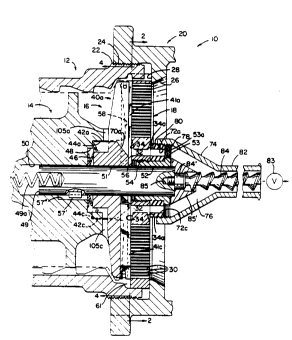
Fig. 1 illustrates the grinding head 10 of a meat
grinder, which includes a tubular housing 12 within which a
feed screw 14 is rotatably mounted. Housing 12 and feed
screw 14 are generally constructed as is known in the art so
that, upon rotation of feed screw 14 within housing 12, meat
or the like is advanced within the interior of housing 12
toward grinding head 10.
A knife assembly, shown generally at 16, is mounted
at the end of the feed screw 14. Knife assembly 16 is
disposed against the inner surface of an orifice plate,
generally shown at 18, which is secured in the open end of
housing 12 by a mounting ring, shown generally at 20. In
accordance with known construction, the end of housing 12 is
~y_ ~rO
~.
11 2103~2~
provided with a series of external threads 22, and mounting
ring 20 includes a series of internal threads 24, adapted to
engage external threads 22 on housing 12. Mounting ring 20
further includes an opening 26 defining an inner lip 28,
which is adapted to engage the outer peripheral portion of
orifice plate 18 to maintain orifice plate 18 in position
within the open end of housing 12.
Referring to Figs. 1 and 2, orifice plate 18 is
provided with a large number of relatively small grinding
openings therethrough, such as shown at 30. The size of
outer openings 30 varies according to the type of meat being
ground. Generally, however, grinding openings 30 range from
3/32 inch to 1/2 inch in diameter. In accordance with known
grinding principles, meat within the interior of housing 12
is forced toward orifice plate 18 by rotation of feed screw
14 and through openings 30, with rotating knife assembly 16
acting to sever the meat against the inner surface of orifice
plate 18 prior to the meat passing through openings 30 in
orifice plate 18.
As is also shown in Figs. 1 and 2, a series of
relatively large inner collection openings or passages 32 are
formed in orifice plate 18 inwardly of the outer grinding
openings 30. Collection openings 32 are located at a common
radius from the center of orifice plate 18, and are equally
radially spaced from each other. Collection openings 32 are
generally oval or slightly kidney-shaped. Illustratively,
collection openings 32 are approximately one inch long and
three-eighths of an inch wide. As will be explained,
collection openings 32 act to collect bone, gristle, sinew or
other hard material prior to its passing through grinding
openings 30 in orifice plate 18 during operation of grinding
head 10.
Each of collection openings 32 is provided with a
ramped entryway 34 opening onto the inner surface of orifice
plate 18. Ramped entryways 34 are disposed at an angle of
approximately 8 degrees to the surface of orifice plate 18,
,Y~
-12- 210372~
and extend outwardly from collection openings 32 in a
direction toward the outer grinding openings 30. In a
preferred embodiment, both the inner and outer surfaces of
orifice plate 18 are provided with ramped entryways 34
leading into collection orifices 32. This arrangement
accommodates mounting of orifice plate 18 at the end of
housing 12 such that either of its surfaces can be employed
as the inner cutting surface against knife assembly 16. In
Fig. 1, the ramped entryways formed in the outer surface of
orifice plate 18 are shown at 34a.
The end walls formed by each of the ramped
entryways 34 provide shearing surfaces such as shown at 36,
the purpose of which will later be explained.
Referring to Figs. 1, 4, and 5, rotating knife
assembly 16 comprises a knife holder consisting of a central
hub portion 38 and a series of knife holding arms 40a, 40b,
40c and 40d extending outwardly therefrom. Knives 41a, 41b,
41c and 41d are mounted in arms 40a-40d, respectively. A
series of drive lugs, shown at 42a, 42b, 42c and 42d, are
formed integrally with hub portion 38 and are in alignment
with the inner portion of each of arms 40a-40d, respectively.
Referring to Fig. 1, lugs 42a-42d are adapted for placement
in mating recesses, such as shown at 44a and 44c, formed in
the end of feed screw 14. Engagement of drive lugs 42a-42d
with the walls of the mating recesses, such as shown at 44a,
44c, causes rotation of knife assembly 16 in response to
rotation of feed screw 14.
A belleville-type spring washer assembly, such as
shown at 46, is placed within an annular inner recess 48
formed in the end of feed screw 14 which extends inwardly
from the mating recesses, such as 44a, 44c, also formed in
the end of feed screw 14. Spring washer 46 bears between the
ends of drive lugs 42a-42d and the inner end wall of annular
recess 48 to bias knife assembly 16 against the inner surface
of orifice plate 18.
.~
~~ -13- 210372~
A centering shaft 49 has its inner end located
within a central bore 50 formed in the end of feed screw 14,
and its outer end extending through a central passage 51
formed in hub portion 38 of knife assembly 16. A spring 49a
is located in a bore formed in the inner end of shaft 49, and
bears against the inner end of bore 50. The outermost end of
centering shaft 49 is received within a central passage 52
provided in a bushing 53. Bushing 53 acts to maintain an
adaptor 53a in position against the outer surface of orifice
plate 18, and includes external threads 54 which engage
internal threads 56 formed in a central opening 57 (Fig. 3)
formed in orifice plate 18. With this arrangement, bushing
53 and orifice plate 18 cooperate to rotatably support the
end of feed screw 14 through centering shaft 49. Centering
shaft 49 is keyed to feed screw 14 by means of a key 57'
mounted to shaft 49 and engaged within a slot 57" associated
with bore 50. In this manner, shaft 49 rotates in response
to rotation of feed screw 14.
Adaptor plate 53a is pinned to orifice plate 18 so
as to be non-rotatable relative to orifice plate 18. As
shown in Fig. 2, orifice plate 18 is provided with a pin-
receiving hole 59, and adaptor plate 53a likewise is provided
with a facing pin-receiving hole (not shown). A pin, or
dowel, is placed within the facing pin-receiving holes in
orifice plate 18 and adaptor plate 53a to fix adaptor plate
53a relative to orifice plate 18.
The mounting of knife assembly 16 to the end of
feed screw 14 as shown and described provides adjustability
of the clearance between the end of the tapered feed screw
pressure flighting, shown at 58, and the inner surface of
orifice plate 18 while maintaining the knives of knife
assembly 16, such as shown it 41a and 41c in Fig. 1, against
the inner surface of orifice plate 18. To increase the
clearance between pressure flighting end 58 and the inner
surface of plate 18, mounting ring 20 is turned on housing
threads 22 so as to move ring 20 rightwardly. While this
.~.
.,
-14- 2103721
takes place, spring washer assembly 46 expands to urge knife
assembly 16 rightwardly so as to maintain the knives against
the inner surface of plate 18, and thereby maintaining the
outer peripheral portion of plate 18 against lip 28 of
mounting ring 20. If necessary, additional spring washers
can be employed.
To decrease the clearance between pressure
flighting end 58 and the inner surface of plate 18, mounting
ring 20 is turned on housing threads 22 so as to move ring 20
leftwardly. This action forces spring assembly 46 to
compress while maintaining the knives against the inner
surface of orifice plate 18.
An annular space 61 (Fig. 1) is located outwardly
of the ends of knife arms 40a-40d. Space 61 allows material
to pass to a succeeding knife arm during rotation of knife
assembly 16.
Referring to Fig. 4, the arrangement of knife
holding arms 40a-40d relative to hub portion 38 is most
clearly illustrated. As shown, arms 40a-40d are arranged so
as to be non-radial relative to hub 38. More particularly,
arms 40a-40d are positioned such that the longitudinal axis
of each of arms 40a-40d is perpendicular to the longitudinal
axis of its adjacent arms. In addition, the knives, such as
shown at 41a, 41c and 41d as mounted to arms 40a, 40c and
40d, respectively, are also perpendicular to each other.
Arms 40a-40d each include a base portion such as
shown at 62a-62d, respectively, which is mounted to hub
portion 38. Arms 40a-40d further include outer end portions
64a-64d, respectively, spaced outwardly from base portions
62a-62d, respectively.
Knife assembly 16 is adapted for rotation in the
direction of an arrow 64, when mounted to the end of feed
screw 14.
Referring to arm 40a (Fig. 4), the orientation of
arm 40a relative to a line 66a extending between the center
of knife assembly 16 and the centroid of base portion 62a of
.,,.~
,
-15- 210372~
arm 40a is such that arm 40a is oriented in the direction of
arrow 64 away from line 66a. Each of arms 40b-40d is
similarly oriented relative to lines 66b-66d, which extend
through the center of knife assembly 16 and the centroid of
the respective base portions 62b-62d. With this arrangement,
the longitudinal axes of arms 40a-40d are tangential to a
common circle concentric with the center of knife assembly
16.
With the forwardly disposed non-radial arrangement
of arms 40a-40d, material located against the inner surface
of orifice plate 18 and engaged by knife arms 40a-40d is
generally swept inwardly toward the center of knife assembly
16 when it is rotated during operation of grinding head 10.
A portion of such material may be swept outwardly upon
rotation of knife assembly 16. Soft tissue is forced through
grinding openings 30 before it reaches the central portion of
plate 18. Hard material such as bone, sinew, gristle or the
like, which does not readily pass through grinding openings
30, rides on plate 18 over openings 30 and is directed
inwardly toward hub portion 38 of knife assembly 16 and the
central area of plate 18. Upon continued rotation of knife
assembly 16, the hard material is directed to ramped
entryways 34 associated with collection openings 32, and is
collected in openings 32. With a large piece of hard
material which cannot pass into collection openings 32, the
piece is lodged within entryway 34 into a collection opening
32 and is forced by knife assembly 16 against shearing
surface 36 defined by the end of ramped entryway 34 in
combination with the end area of collection opening 32. One
of the knives (41a-41d) engages the piece of hard material,
and cooperates with shearing surface 36 to cut the piece of
material lodged within entryway 34. The portion of material
within entryway 34 is then passed into collection opening 32,
while the remainder of the piece of material is directed by
the knife assembly into another of entryways 34. The above-
described action repeats until the piece of material is
. i
,~
-16- 2103724
reduced to a size small enough to pass in its entirety
through one of collection openings 32.
It should be appreciated that knife arms 40a-40d
may alternatively be arranged radially relative to hub
portion 38, or arranged non-radially with arms 40a-40d being
angled rearwardly. The specific arrangement of arms 40a-40d
will be determined largely by the type of grade of material
being ground. In any case, it has been found that hard
material displays a tendency to migrate toward the center
upon rotation of the knife assembly. This tendency simply
increases when the knife arms are angled forwardly.
Referring to Figs. 1, 4 and 5, knife assembly 16
includes pockets 68a, 68b, 68c and 68d formed in hub portion
38. Pockets 68a-68d are disposed forward of the forward
edges of knife arms 40a-40d, respectively. Each of pockets
68a-68d is defined in part by an outwardly facing ramped
surface 70a-70d, respectively. Referring to Fig. 1, the
ramped surfaces, such as 70a, are located on hub portion 38
so as to intersect a longitudinal axis through each of
collection openings 32. The ramped surfaces, such as 70a,
cooperate with ramped entryways 34 into collection openings
32, to define a passage for directing hard material into
ramped entryways 34 and collection openings 32. Pockets 68a-
68d provide a low pressure region toward the center of knife
assembly 16, for facilitating passage of material inwardly
toward the central portion of orifice plate 18 during
rotation of knife assembly 16. In this manner, hard material
which does not readily pass through grinding openings 30 is
directed into ramped entryways 34 and collection openings 32.
Adaptor plate 53a is provided with a series of
spaced passages therethrough, shown in Fig. 1 at 72a and 72c.
The passages (72a, 72c) in adaptor plate 53a are placed into
alignment with collection openings 32 in orifice plate 18,
when adapter plate 53a is pinned to plate 18 as described
previously.
,;3
-17- 210~72i
A collection cup 74 having a collection cavity 76
is mounted to adaptor plate 53a by internal threads 78
provided on collection cup 74 engaging external threads 80
formed on bushing 53. A discharge tube 82 extends from the
outer end of cup 74, and includes an internal passage adapted
to receive material from collection cavity 76. A valve 82
may be provided downstream of discharge tube 82 for
controlling the pressure in tube 82 and the rate of discharge
of hard material therefrom. Valve 83 is preferably
adjustable so that an optimal pressure setting can be
attained to ensure that substantially all hard material
passes into collection openings 32 while a maximum amount of
soft tissue passes through grinding openings 30 before being
forced by knife assembly 16 into the central area of orifice
plate 18. This pressure may also be controlled by adjusting
the amount of engagement between collection cup internal
threads 78 and adaptor plate threads 80, and thereby the
amount of flow restriction provided by collection cavity 76.
A discharge auger 84 is mounted to the end of
centering shaft 49 and is rotatable therewith in response to
rotation of feed screw 14, for assisting in discharging the
collected hard material from collection cavity 76 of cup 74
and into the internal passage of discharge tube 82.
Discharge auger 84 is provided at its inner end with a non-
circular hub 84', and a threaded stub shaft extends from hub
84' into engagement with internal threads provided in a bore
85 formed in the outer end of centering shaft 49. A
frustoconical collar member 85' is mounted to the end of
centering shaft 49 along with discharge auger 84, and is
rotatable therewith by engagement of auger hub 84' with the
walls of an internal passage formed in collar member 85' in
which hub 84' is located. In this manner, collar member 85'
is rotatable along with discharge auger 84 in response to
rotation of feed screw 14.
The outer walls of collar member 85' are oriented
substantially parallel to the inner walls of collection cup
~-- 210372~
-18-
74, so that a tapered annular passageway is formed in
collection cavity 76 through which the collected hard
material passes into the internal passage of discharge tube
82. Discharge auger 84 assists in moving the collected hard
material into and through the internal passage of discharge
tube 82, to reduce the back pressure within collection cavity
76 and to facilitate passage of collected hard material
through collection openings 32 and the passages, such as 72a,
72c, formed in adaptor plate 53a and into collection cavity
76.
Reference is now made to Figs. 1 and 5-7 for an
explanation of the manner in which knives 41a-41d are mounted
to knife arms 40a-40d, respectively. As shown in Fig. 5,
arms 40a-40d are provided with knife mounting slots 86a-86d,
respectively. Each of slots 86a-86d extends throughout the
length of its respective knife arm, and opens into central
passage 51 provided in hub portion 38 of knife assembly 16.
Slots 86a-86d are slanted relative to the outer faces of
knife arms 40a-40d, respectively, to provide a forward angled
orientation of knives 41a-41d relative to the outer faces of
knife arms 40a-40d, respectively.
- Referring to Fig. 7, knife arm 40c and knife 41c
are illustrated. A knife mounting pin 88c is provided toward
the outer end of knife arm 40c, extending transversely
through knife mounting slot 86c. Knife mounting pin 88c is
pressed-fit into a transverse opening formed in the outer end
of knife arm 40c. Knife 41c includes an outwardly facing
knife mounting slot 90c formed in its outer end. Knife 41c
is mounted to knife arm 40c by first inserting the length of
knife 41c into slot 86c so that the outer end of knife 41c
clears knife mounting pin 88c. In this position, a portion
of the inner end of knife 41c is disposed within passage 54
formed in hub portion 38. Knife 41c is then slid rightwardly
within knife mounting slot 86c, so that pin-receiving slot
90c in its outer end receives knife mounting pin 88c and pin
88c engages the inner end of pin-receiving slot 90c. After
.,~7
I ~ r
-
-19- 210~72~
centering shaft 49 is inserted through passage 51 formed in
hub portion 38, leftward movement of knife 41c within knife
mounting slot 86c results in the leftward end of knife 41c
engaging centering shaft 49 before knife mounting pin 88c
exits pin-receiving slot 90c. In this manner, knife 41c is
positively retained within knife mounting slot 86c of the
knife arm 40c.
Knives 41a, 41b and 41d are retained in knife
mounting slot 86a, 86b and 86d, respectively of knife arms
40a, 40b and 40d in a similar manner.
Fig. 6 illustrates a prior art system of mounting a
knife within a knife arm. Like reference characters will be
used where possible to facilitate clarity. In the
arrangement shown in Fig. 6, knife arm 40c again includes a
knife mounting slot 86c which extends throughout the length
of knife arm 40c between its outer end and inwardly opening
into passage 51. A knife mounting pin 92c is press-fit into
an opening formed in the rearward portion of knife arm 40c,
with its forward edge extending into knife mounting slot 86c.
Knife 41c is provided with a notch 94 which receives the end
of pin 92c. With this arrangement, knife 41c is not
positively retained within knife mounting slot 86c. Rather,
pin 92c and notch 94 simply cooperate to fix to lateral
position of knife 41c relative to knife arm 40c. With the
knife mounting arrangement as illustrated in Fig. 7,
providing positive retention of the knives within the knife
mounting slots formed in the knife arms, changing of orifice
plates is accomplished in a quicker and more efficient
manner, in that the operator does not have to be concerned
with making sure the knives do not fall out of the knife
mounting slots formed in the knife arms. As long as
centering shaft 49 remains in place in passage 51 formed in
hub portion 38 of knife assembly 16, the knives are
positively retained and cannot be removed from the knife
mounting slots.
c~
-20- 210372~
Referring to Figs. 4 and 5, the forward face of
knife arm 40b is provided with a forwardly extending ramped
surface, shown at 100. While not visible in Figs. 4 and 5,
the forward face of knife arm 40d is similarly provided with
a forwardly extending ramped surface. As shown in Fig. 5,
the forward face of knife arm 40c is provided with a
rearwardly extending ramped surface 102. Knife arm 40a,
which is opposite knife arm 40c, is similarly provided with a
rearwardly extending ramped surface.
When rotating knife assembly 16 is mounted to the
end of feed screw 14, knife arms 40a and 40c are located
adjacent the termination of the pressure flights, such as
shown in phantom in Fig. 4 at 103a and 103c, at the end of
feed screw 14. Accordingly, arms 40b and 40d are located at
to the pressure flight terminations 103a, 103c. With this
arrangement, the rearwardly (or inwardly) extending ramped
surfaces on knife arms 40a and 40c act to relieve some of the
pressure generated by the pressure flight terminations 103a,
103c during rotation of feed screw 14. The forwardly (or
outwardly) extending ramped surfaces, such as surface 100 on
the forward face of arm 40b, act to generate pressure forcing
the material toward the inner surface of orifice plate 18 at
arms 40b, 40d during rotation of feed screw 14. In this
manner, the pressure forcing the material toward orifice
plate 18 is more evenly distributed between arms 40a, 40c.
Gaps, such as shown at 104a and 104c in Fig. 4, are
present between pressure flight terminations 103a, 103c and
the forward faces of knife arms 40a, 40c, respectively. Gaps
104a, 104c lead to passages, such as shown at 105a, 105c in
Fig. 1, formed between the inner surfaces of the knife arms
and the end of feed screw 14. The gaps, such as 104a and
104c, and the passages, such as 105a and 105c, cooperate to
allow hard material to pass rearwardly from one knife arm to
the next during rotation of the knife assembly. This
provides further insurance that hard material is not
r~
-21- 21~372~
excessively forced against the inner surface of orifice plate
18 before it reaches collection openings 32.
Figs. 8 and 9 illustrate an alternate arrangement
for the ramped surfaces leading into collection openings 32
formed in orifice plate 18. In this arrangement, the knife
assembly rotates in the direction of an arrow 106. The
ramped surface leading into collection opening 32 is shown at
108. Ramped surface 108 extends outwardly toward the outer
grinding orifices 30 formed in orifice plate 18, tapering
upwardly and outwardly from collection opening 32. Ramped
surface 108 terminates at its rightward end in a shearing
edge 110, which is substantially triangular in shape. Ramped
surface 108 intersects the inner surface of orifice plate 18
at a line shown at 112, which extends between the outer end
of shearing edge 110 and the leftward end of collection
opening 32. This arrangement acts to force the hard material
downwardly on ramped surface 108 toward collection opening 32
and shearing edge 110, so that a maximum amount of area of
shearing edge 110 is available for acting on the hard
material along with the knives to shear the hard material off
and to facilitate its passage into collection openings 32.
Ramped surface 108 is substantially in the form of a right
triangle defined between shearing edge 110, the outer wall of
collection opening 32, and line of intersection 112.
Ramped surface 108 has a depth of approximately 1/8
inch at the outer wall of collection opening 32, and is
inclined relative to the inner surface of orifice plate 18 at
an angle of approximately 8.5~.
With some types of material being ground, a
situation sometimes arises in which a substantial amount of
usable soft tissue passes through collection openings 32
along with the hard material. In such situations, it is
desirable to recover the usable soft material in order to
reduce the amount of wasted usable material. Figs. 10-13
illustrate two arrangements for recovering usable material
which passes through collection openings 32.
~.
~,~'
2103721
-22-
Referring to Fig. 10, a recovery grinding
arrangement 120 generally includes a cylindrical housing
member 122 having internal threads 124 for engaging external
threads 80 provided on adaptor plate 53a. Housing 122
defines an internal collection cavity 126, and an opening 128
is provided at the outer end of housing member 122.
In the same manner as described previously with
respect to Fig. 1, a discharge auger 84 is mounted to the end
of centering pin 49 and is rotatable therewith in response to
rotation of feed screw 14. Discharge auger 84 is located
within a discharge passage formed in a discharge tube 130,
which is threadedly engaged with a central passage formed in
a secondary orifice plate, shown at 132. As with orifice
plate 18, secondary orifice plate 132 is provided with a
series of discharge orifices 134, which may be somewhat
smaller in diameter than orifices 30 formed in primary
orifice plate 18.
Secondary orifice plate 132 engages an inwardly
extending lip which forms opening 128 in the outer end of
housing 122.
A recovery knife assembly 136, shown in Figs. 10
and 11, is located between the end of centering shaft 49 and
the inner surface of secondary orifice plate 132. Recovery
knife assembly 136 generally comprises a disk-like body
portion 138 having a square aperture 140 formed therein. The
hub of discharge auger 84 is placed within aperture 140, so
that recovery knife assembly 136 is rotatable in response to
rotation of centering shaft 49 and feed screw 14. Body
portion 138 includes a pair of bevelled surfaces 139a, 139b.
Spring 49a (Fig. 1) urges recovery knife assembly
136 against the inner surface of secondary orifice plate 132.
Recovery knife assembly 136 further includes a pair
of angled flights 142a, 142b, which terminate in a
pair of knife tips 144a, 144b, respectively. Material
passing through the passages, such as 72a, 72c, formed in
adaptor plate 53a, is picked up by flights 142a, 142b and fed
,. .
-23- 210372-~
thereon toward knife tips 144a, 144b and toward the inner
surface of secondary orifice plate 132. The hard material
migrates along bevelled surfaces 139a, 139b toward the center
of recovery knife assembly 136 and into the inlet of the
internal passage provided in discharge tube 130. The soft
material migrates outwardly toward orifices 134 formed in
orifice plate 132, and is forced therethrough by pressure
generated by flights 142a, 142b upon rotation of recover
knife assembly 136.
The ground soft material which is discharged
through orifices 134 in secondary orifice plate 132 mixes
with the ground soft material discharged from the orifices
formed in primary orifice plate 18, and thereby is incorpo-
rated into the final ground product.
As in the embodiment of Fig. 1, discharge auger 84
acts to move the collected hard material through the passage
of discharge tube 130, for ultimate collection in a
receptacle (not shown). A valve, such as 83 in Fig. 1, may
be provided downstream of the discharge of discharge tube 130
for regulating the amount of pressure within discharge tube
130 and collection cavity 126. In this manner, an optimal
operating condition can be attained so as to recover a
maximum amount of soft material through secondary orifice
plate 132 while removing substantially all hard material from
the final ground product.
Fig. 12 illustrates a recovery grinding arrangement
150. In this arrangement, a cylindrical housing 152 is
provided with internal threads 154 which engage external
threads 80 on adaptor plate 53a. Housing 152 is provided
with a series of relatively small upwardly facing orifices
156 extending through the upper portion of its side wall.
Orifices 156 are formed in the wall of housing 152 throughout
an arc ranging between 60 and 120C. As shown in Fig. 13,
the arc encompassing orifices 156 is approximately 60.
Housing 152 includes an end wall 158 which partially closes
its end opposite the open end in which internal threads 154
~ :i
-24- 210372~
are formed. An annular ring of relatively small orifices 160
is formed in end wall 158. An internally threaded nipple 162
is provided in end wall 158, and a discharge tube 164 having
external threads at one of its ends is adapted for connection
to nipple 162. With this arrangement, the internal discharge
passage of discharge tube 164 is placed into communication
with the interior of cylindrical housing 152.
A rotating recovery knife, assembly 166 is disposed
within the interior of housing 152. Knife assembly 166
includes a knife holding member 168 having three equally
radially spaced axially extending lobes provided with
outwardly facing slots in which knives 170 are mounted. Each
lobe is formed by a substantially radial front surface 172
which merges into a leading surface 174 in a direction toward
the preceding lobe. Each lobe further includes an outer
surface 176 located inwardly of the inner wall of housing
152, and extending between the front surface 172 and the
leading surface 174 of the succeeding lobe.
The slot formed in each lobe angles inwardly toward
the center of knife holding member 168 in a direction toward
end wall 158, such as illustrated by slot 178 in Fig. 12.
Each knife 170 is provided with an inner surface having an
angle adapted to mate with the angled inner surface of the
slots, so as to maintain the outer edge of each knife 170 in
contact with the inner surface of housing 152 throughout the
length or knife 170. In addition, knives 170 have a height
at their outer ends which extends throughout the thickness of
the annular ring of orifices 160 formed in end wall 158. The
end of knives 170 is in contact with the inner surface of end
wall 158 throughout the width of the ring of orifices 160.
As in the Fig. 10 embodiment, spring 49a (Fig. 1)
urges recovery knife assembly 166 against end wall 158 of
housing 152.
Knife holding member 168 is provided at its inner
end with a square recess 180 facing the outer end of
centering shaft 49. Centering shaft 49 is provided with a
,~.
210372~
-25-
square projection 182 which mates with the side walls of
square recess 180, so as to impart rotation to knife holding
member 168 in response to rotation of centering shaft 49
caused by rotation of feed screw 14.
The outer end of knife holding member 168 is
provided with an internally threaded bore 184. A discharge
auger 186 has an externally threaded stub shaft 188, which is
engageable with threaded bore 184 to secure discharge auger
186 to knife holding member 168. With this arrangement,
rotation of knife holding member 168 causes rotation of
discharge auger 186, to advance hard material through the
discharge passage of discharge tube 164.
In operation, the embodiment of Fig. 12 functions
as follows. In a manner as described above, hard material is
routed through collection openings 32 in orifice plate 18 to
the discharge passages in adaptor plate 53a, such as shown at
72a and 72c, and into the interior of cylindrical housing
152. A certain amount of usable soft material is included
with the hard material, and the soft material migrates
outwardly toward the inner wall of housing 152, while the
hard material migrates inwardly. The usable soft material is
forced upwardly through orifices 156 in housing 152, and is
severed by knives 170. In a similar manner, the soft
material is forced outwardly through the ring of orifices 160
formed in end wall 158 and is severed by the ends of knives
170. The discharged soft material passing through orifices
156 and 160 is mixed with the ground soft material discharged
from the upper portion of primary orifice plate 18, flowing
downwardly along the sides of housing 152 into a hopper or
the like. The hard material is routed along leading surfaces
174 of knife holding member 168 toward its outer end, and
from there passes into the opening of nipple 162 and the dis-
charge passage of discharge tube 164. Discharge auger 186
moves the hard material through discharge tube 164, thus
creating a low pressure area at the entrance into nipple 162
to facilitate drawing the hard material thereinto.
-26- 2103724
In an alternate embodiment, the annular ring of
small orifices 160 formed in end wall 158 can be eliminated,
thus providing only radial upward flow of the recovered
material through orifices 156 formed in housing 152.
While the invention as shown and described provides
several features which enhance the ability of grinding head
10 to collect hard material during operation, it is
understood that certain of the described features could be
employed without other of the described features to yield
improved hard material collection. For example, an orifice
plate 18 constructed according to the invention could be
employed with a prior art knife assembly, and would result in
improved ability to collect hard material due to the
advantages offered by ramped entryways 34 leading into
collection openings 32. Knife assembly 16 as shown and
described could be employed with a prior art orifice plate
which does not include ramped entryways, and would result in
improved hard material collection due to advantages in
directing material inwardly offered by the construction of
knife assembly 16. Recovery grinding arrangement 120 and 150
could be employed with a prior art grinding and hard material
collection system, to provide recovery grinding of usable
soft material which is collected along with the hard
material. To most effectively collect hard material and
recover usable material, however, the features as described
are combined into a single structure.
The adjustability feature described previously, in
which the clearance provided between the inner surface of
orifice plate 18 and the end 58 of the pressure flighting,
allows the operator to adjust grinding head 10 according to
the hard material conditions in the meat being ground. For a
lower grade of meat, which may contain large pieces of hard
material, the clearance between the inner surface of orifice
plate 18 and pressure flighting end 54 is increased. This
allows the large pieces of material to ride on the inner
surface of orifice plate 18 without being repeatedly
,;~,~,
-
-27- 210372~
subjected to pressure exerted by pressure flighting end 54,
which otherwise may cause the piece of material to chip
against grinding orifices 30. In this manner, the large
piece of material is directed inwardly toward collection
orifices 32 without being repeatedly subjected to exertion of
pressure, and is reduced in size as described previously for
ultimate passage through collection openings 32. When a
higher grade of meat is being ground, and which contains
smaller pieces of hard material, the clearance between the
inner surface of orifice plate 18 and pressure flighting end
54 is decreased. In all situations, however, knife assembly
16 is urged against the inner surface of orifice plate 18 by
spring washer assembly 46.
Figs. 14-16 illustrate an alternative embodiment
for the ramped entryways leading into collection openings 32,
somewhat similar to the embodiment shown in Fig. 8. In the
embodiment of Fig. 14, the knife assembly rotates in the
direction of arrow 200. Each ramped entryway includes a
ramped surface 202 which intersects the surface of orifice
plate 18 and increases in depth in the direction of arrow
200. The line of intersection between ramped surface 202 and
the surface of orifice plate 18 extends perpendicular to the
major axis of collection opening 32, and extends tangentially
from the arcuate end of collection opening 32.
An end wall 204 extends between the lowermost end
of ramped surface 202 and the surface of orifice plate 18.
The line of intersection between the surface of orifice plate
18 and end wall 204 extends from the outermost point defined
by the intersection of ramped surface 202 with the surface of
orifice plate 18 tangentially to the other arcuate end of
collection opening 32. This orientation of end wall 204 acts
to direct material toward the downstream end of collection
opening 32 and the shearing edge defined thereby in
combination with the surface of orifice plate 18, to shear
the hard material as the rotating knife assembly passes over
the downstream ends of collection openings 32.
210372~
-28-
Illustratively, ramped surface 202 at its
intersection with the outer edge of collection opening 32 is
disposed at an angle a (Fig. 16) of approximately 11.7,
tapering upwardly in an outward direction toward the
outermost point defined by ramped surface 202, where it
merges with the surface of orifice plate 18. End wall 204 is
oriented at an angle of 90- to ramped surface 202, so that
the angle b (Fig. 16) between the surface of orifice plate 18
and end wall 204 is approximately 78.3.
Fig. 17 illustrates a hard material discharge
system, shown generally at 210, for controlling the output of
hard material from the spaced passages, such as 72a, 72c,
formed in adaptor plate 53a. Hard material discharge system
210 includes a cup member 212 having internal threads which
engage external threads 34a formed on adaptor plate 53a.
Cup member 212 includes internal walls defining a
collection cavity 214. Cavity 214 is defined by an upstream
straight wall section 216, and a downstream tapered wall
section 218 which is frustoconical in longitudinal cross
section. Cup member 212 further defines an annular passage
219 in its outer end, which extends outwardly from cavity
214.
An adaptor member 220 is mounted to a flange 220a
defined by the outer end of cup member 212. Adaptor member
220 includes a mounting flange 221 engageable with cup member
flange 220a, an internal passage 222, and a tapered annular
wall 223 which defines the entrance into passage 222 at the
upstream end of adaptor member 220.
Adaptor member 220 is secured to cup member 220a
flange in any satisfactory manner. For example, a
conventional clamp may be employed to secure adaptor member
flange 221 to the cup member flange 220a, or external threads
can be formed on cup member flange 220a, and an internally
threaded clamping ring threaded onto the external threads of
the cup member flange. A resilient 20A durometer urethane
gasket or washer 221a is disposed between adaptor member
-
- 29 - 2103721
flange 221 and cup member flange 220a. A flexible Tigon*
tube is adapted to be connected to the outer end of adaptor
member 220 for conveying hard material discharged from
adaptor member 220 to a satisfactory receptacle or the like.
Resilient washer 221a accommodates any misalignment between
discharge auger 224 and discharge passage 222 of adaptor
member 220. As set forth above, discharge auger 224 is
mounted to the end of feed screw centering pin 49, while cup
member 212 and adaptor member 220 are mounted to orifice
plate 18 through adaptor plate 53a. Centering pin 49 is
subjected to wear during operation and resilient washer 221a
is compressible to accommodate resulting misalignment between
discharge auger 224 and adaptor member passage 222.
As in the previous embodiments, a discharge auger
224 is mounted to the end of feed screw centering shaft 49,
and is rotatable therewith in response to rotation of feed
screw 14. Discharge auger 224 acts to move material located
within cavity 214 in a leftward-to-rightward direction
through cavity 214. Discharge auger 224 extends throughout
the length of cavity 214, through passage 219 formed in the
outer end of cup member 212, and into and partially through
adaptor member passage 222.
Referring to Fig. 19, a series of spaced, axial
semi-circular flutes 225 are formed in the outer end of
collection cup 212. Flutes 225 define axial grooves in the
internal wall which defines collection cup passage 219,
extending longitudinally throughout the length of passage 219
and opening into collection cavity 214.
Referring to Figs. 17-19, in an illustrative
application in which orifice plate 18 is a conventional 11
inch diameter plate having a large number of 5/64" or 1/8"
orifices therethrough, secondary discharge auger 224 extends
6 inches from the end of centering pin 49 and has an outside
diameter of 0.865", and provides flighting which has a pitch
of 0.5 inches and a depth of 0.125 inches. Adaptor member
*Trade-mark
.
~'
-
~30- 2103724
220 has a length of approximately 4.25 inches, and secondary
discharge auger 223 extends approximately 4/5ths of the
length of adaptor member 220 terminating approximately one
inch short of its outer end. Passage 219 formed in the
outer end of cup member 212 defines an internal diameter of
1.00 inches, and flutes 225 have a depth of approximately
0.1875 inches. Adaptor member passage 222 defines an
internal diameter of 0.875 inches, providing a very close
tolerance between the outside diameter of discharge auger 224
and the internal wall defining passage 222.
The arrangement Fig. 17 essentially provides a
rotating path between discharge auger 224 and the internal
wall of passage 222, defined by the flighting of discharge
auger 224, for moving hard material through adapter member
passage 222 upon rotation of secondary discharge auger 224.
Back pressure is provided in collection cavity 214 to allow
primarily only hard material to pass through the passages,
such as 72a, 72c in adaptor plate 53a and into collection
cavity 214. A minimal amount of usable soft material is
passed through adaptor member passage 222 upon rotation of
secondary discharge auger 224.
In operation, when hard material within collection
cavity 214 reaches passage 219 and flutes 225, the material
is forced along the length of passage 219 and flutes 225 by
rotation of discharge auger 224. At the same time, discharge
auger 224 acts in cooperation with flutes 225 to shear the
hard material and thereby reduce it in size. In addition,
flutes 225 keep the hard material from spinning, providing an
axial passageway in combination with passage 219 to force the
hard material rightwardly toward tapered entryway 223 and
adaptor member passage 222.
The flow rate of hard material discharged from
collection cavity 214 can be calibrated by varying the
diameter of discharge auger 224 and the pitch and depth of
its flighting, along with the diameter of adaptor member
passage 222, in order to attain an optimum back pressure in
~'
-
-31- 21 03 721
collection cavity 214 to maximize discharge of hard material
and minimize discharge of soft material. For example, when
an orifice plate 18 having larger orifices is used, discharge
auger 224 is removed and replaced with a discharge auger with
flighting having a greater pitch and/or depth, to increase
the flow rate of hard material from collection cavity 214 and
into and through adaptor member passage 222. This prevents
excessive back pressure from building up within collection
cavity 214, which may otherwise result in hard material
passing through the orifices formed in orifice plate 18.
In some instances, when the flow rate of hard
material through adaptor member passage 222 is increased, it
has been found that an increased amount of soft material,
typically in the form of fat, is discharged through passage
219 and adaptor member passage 222 upon rotation of discharge
auger 224. When this occurs, adaptor member 220 is removed
and replaced with an adaptor member 226 (Fig. 20). Adaptor
member 226 includes a larger number of relatively small
orifices 227, essentially defining a tubular screen
throughout a portion of the length of adaptor member 226.
Illustratively, each of orifices 227 may have a diameter of
0.0761 inches, formed in 24 staggered rows having 15 holes
per row located at 15 increments around the outside diameter
of adaptor member 226. The length of the rows of orifices
227 may be approximately 1.942 inches. With this structure,
it has been found that hard material is maintained within the
flights of the discharge auger, and soft material is squeezed
out through openings 227. The soft material discharged
through openings 227 can be collected in a receptacle bolted
onto cup member 212, or it can be rerouted back into the
grinder chamber for mixing with the meat being ground.
Fig. 21 illustrates yet another hard material
discharge system, shown generally at 230, for controlling the
output of hard material from the spaced passages, such as
72a, 72c, formed in adaptor plate 53a. Hard material
discharge system 230 includes a cup member 232 having
;~,,
-32- 210372~
internal threads which engage external threads 34a formed on
adaptor plate 53a.
Cup member 232 is generally formed similarly to cup
member 212 shown in Fig. 20, defining an internal collection
cavity 234 having an upstream straight wall section 236 and a
downstream tapered wall section 238. Cup member 232 further
defines an annular passage 240 in its outer end, which
extends outwardly from collection cavity 234. A series of
flutes 242 are provided in passage 240, similarly to flutes
225 formed in passage 219 of collection cup 212 (Fig. 17).
In this embodiment, a discharge auger 244 extends
partially through passage 240, with its outer end being
located upstream of the end of passage 240 and flutes 242.
A sleeve 246 is mounted to the outer end of
collection cup 232, such as by welding or the like. Sleeve
246 is substantially cylindrical, and includes a series of
external threads 248, located at its outer end. An insert
250 is located within the interior of sleeve 246. Insert 250
is constructed of a plastic or nylon material, and includes a
tapered axial passage 252 extending throughout its length.
Passage 252 provides an inlet at its upstream end in
communication with passage 240 and flutes 242, and tapers
inwardly in a left-to-right direction, terminating in an
outlet at the downstream end of insert 250.
A flexible resilient diaphragm 254 is positioned in
the interior of sleeve 246 at the outlet of passage 252, such
that the upstream face of diaphragm 254 abuts the downstream
end of insert 250. Diaphragm 254 is constructed of a
resilient material such as urethane. A central aperture 256
extends through diaphragm 254, and is in communication with
the outlet of passage 252.
A discharge adaptor or tube 258, defining a
discharge passage 260, is secured to sleeve 246 by means of a
retaining ring 262. Retaining ring 262 engages a shoulder
formed on a mounting portion 264 which is integral with
discharge tube 258. Mounting portion 264 further includes a
~,
, ,
~33~ 210372~
tapered seating surface 266, which is engageable with a
mating tapered seating surface 268 defined by the outer end
of sleeve 246. With this arrangement, insert 250 and
diaphragm 254 are secured within collar 246 by first
inserting discharge tube 258 through retaining ring 262, and
then threading ring 262 onto external threads 248 provided on
sleeve 246 until engagement of seating surfaces 266, 268.
The upstream end of insert 250 abuts the end wall defined by
cup member 232 onto which passage 240 and flutes 242 open,
and diaphragm 254 is sandwiched between the downstream end of
insert 250 and the upstream end of discharge tube 258.
Diaphragm 254 and insert 250 can be changed simply by
removing retaining ring 262 and positioning a new insert and
diaphragm within sleeve 246 in the same manner as described
above.
In operation, hard material discharge system 230
functions as follows. Hard material is forced through the
passages, such as 72a, 72c formed in adaptor plate 53a upon
rotation of the knife assembly, in the same manner as
described previously, and discharged into the portion of
collection cavity 234 defined by inner wall 236. Continued
supply of hard material through the adaptor plate passages,
such as 72a, 72c, results in leftward-to-rightward movement
of the hard material through collection cavity 234 along
tapered wall 238 defining the downstream portion of collec-
tion cavity 234. While the knife assembly is rotating,
discharge auger 244 rotates simultaneously, to assist in the
leftward-to-rightward movement of the hard material through
collection cavity 234. The hard material is forced through
passage 240 and flutes 242, which act to shear the hard
material to reduce it in size. From passage 240 and flutes
242, the hard material enters the inlet of insert passage
252, and is forced therethrough by pressure toward the outlet
of insert passage 252 and diaphragm aperture 256. When
particles of hard material which are smaller than aperture
256 arrive at the outlet of insert passage 252, such
, . ~
34 2103724
particles are forced through diaphragm passage 256 simply due
to back pressure within passage 252. When particles of hard
material larger than aperture 256 arrive at the outlet of
insert passage 252, such particles lodge within and block
diaphragm aperture 256 until sufficient back pressure is
developed within passage 252 to force diaphragm 254 to flex
rightwardly, resulting in aperture 256 expanding a sufficient
amount to allow the hard material particles to pass
therethrough. Diaphragm 254 then returns, at least
partially, to its flexed condition to once again reduce the
size of aperture 256. Tapered insert passage 252, in
combination with diaphragm 254, act to provide a restriction
in the flow of hard material through hard material discharge
system 230 and into passage 260 of discharge tube 258.
The construction of hard material discharge system
230 allows an operator to vary the amount of restriction
provided by insert 250 and the amount of back pressure
required to discharge a particle of hard material through
diaphragm aperture 256, simply by providing different
configurations of the passage through insert 250 and varying
the thickness of diaphragm 254. These variables can be
adjusted according to the amount of hard material present in
the meat being ground and the size of the orifices in orifice
plate 18 to increase or decrease the flow rate of hard
material into discharge passage 260.
It has been found that providing such a restriction
in the hard material discharge system, such as in systems
210, 230, substantially increases the pressure within
collection cavity, such as 214, 234. Notwithstanding this
increase in pressure, the hard material collected upon
rotation of the knife assembly and forced toward the center
of orifice plate 18 continues to be supplied through orifice
plate collection openings 32, and through the adaptor plate
passages, such as 72a, 72c. It has further been found that,
when a particle of hard material is forced into the
collection cavity in this manner, a like volume of soft
,.,. c .
2103724
material present within the collection cavity, such as 214,
234, is displaced in a right-to-left direction back to the
grinding surface of orifice plate 18. This results in a
minimal amount of usable soft material being discharged with
the hard material through the hard material discharge system,
such as 210, 230, thus minimizing waste of usable material
during grinding.
Figs. 22 and 23 illustrate a flow-controlling
nozzle arrangement, shown generally at 270, which is adapted
for mounting to the end of a discharge tube such as 82, 220
or 258, or a flexible hose which may be connected to the end
of such a discharge tube. Nozzle arrangement 270 can be
employed either in connection with a system such as shown in
Figs. 17 and 21, which provide a restriction in the flow of
hard material passing through the system, or with a system
such as shown in Figs. 1, 10 and 12, which do not provide a
restriction to the discharge of hard material.
Nozzle arrangement 270 consists generally of a
valve body 272, which is substantially cylindrical, and
includes an enlarged rear mounting portion 274 within which
the outer end of a discharge tube, such as shown at 275, is
secured. Valve body 272 defines an axial internal passage
276 which communicates with the interior of discharge tube
275 to receive discharged hard material therefrom. Valve
body passage 276 defines an inlet end adjacent the outlet of
discharge tube 275, and an outlet end which terminates in a
nozzle discharge opening, over which a movable valve plate
278 is positioned. The nozzle discharge opening is
substantially circular when viewed along the axis of passage
270. A seating surface, the lower portion of which is shown
at 280 and the upper portion of which is shown at 282, is
formed on valve body 270, with the nozzle discharge opening
extending inwardly from the seating surface. The seating
surface extends about the entire periphery of the nozzle
discharge opening, and is oriented at an angle of
approximately 45~ to the longitudinal axis of passage 276.
_ J~
-36- 210372~
Valve plate 278 is movable between a closed
position, as shown in Fig. 22 in which it lies in a plane
substantially 45 to the longitudinal axis of passage 276,
and an open position in which its lower free end, which is
shown disposed against lower portion 280 of the seating
surface, is moved away therefrom so as to establish
communication between passage 276 and the exterior body 270.
Valve plate 278 is formed integrally with a
rearwardly extending elongated mounting member 284, which is
provided with an upwardly extending lip 286 at its rearward
end. Mounting member 284 is disposed within a channel 288
formed in the upper surface of valve body 270.
A clamping plate 290 is positioned within channel
288 above mounting member 284. A clamping ring 292, having a
set screw 294, is assembled onto valve body 270 to retain
clamping plate 290 and mounting member 284 in position within
channel 288, and to fix the position of clamping plate 290
relative to mounting member 284.
Clamping plate 290 and clamping ring 292 can be
moved to varying positions within channel 288 along the
length of mounting member 284. Positioning clamping plate
290 rearwardly such that its rearward end engages upwardly
extending lip 286 provided on mounting member 284, and then
securing clamping ring 292 so as to fix the position of
clamping plate 290, results in clamping plate 290 and
mounting member 284 cooperating to provide a minimal amount
of resistance to valve plate 278 moving away from its closed
position. On the other hand, moving clamping plate 290 to
its position as shown in Fig. 22 and then securing clamping
ring 292 in the illustrated position, results in clamping
plate 290 and mounting member 284 cooperating to provide a
maximum amount of resistance to movement of valve plate 278
away from its closed position.
When hard material is discharged from discharge
tube 275 and into passage 276 of valve body 270, the hard
material comes into contact with valve plate 278 prior to its
' f ~
-37~ 2103724
discharge from valve body 270. When a sufficient amount of
back pressure is built up within passage 276, clamping plate
278 is moved away from its closed position so as to allow the
hard material to be discharged from the nozzle discharge
opening formed in valve body 270. Movement of clamping plate
290 to its position as shown in Fig. 22 results in a maximum
amount of resistance to movement of clamping plate 278 away
from its closed position, to maintain a relatively high level
of back pressure within passage 276 and discharge tube 275.
This provides advantageous operation during grinding of meat
with a large quantity of hard material, to insure that
primarily hard material is discharged while a maximum amount
of soft material is ground. Conversely, when hard material
conditions are lighter, clamping plate 290 may be moved
rearwardly so as to reduce the amount of resistance provided
by clamping plate 258 to movement away from its closed
posltlon.
The advantages offered by the invention in
collecting hard material and recovering collected soft
material allows an operator to use a lower grade of meat to
be ground which typically includes a greater amount of hard
material than does a higher grade of meat. Accordingly, the
operator can reduce the cost of producing ground meat by
employing a lower grade of material, while yielding a final
ground meat product which is comparable in quality to that
attained with use of a higher grade raw material in a prior
art system.
Various alternatives and embodiments are
contemplated as being within the scope of the following
claims, particularly pointing out and distinctly claiming the
subject matter regarded as the invention.