Note: Descriptions are shown in the official language in which they were submitted.
WO 93/12888 PCT/US92/11200
2.~~3~~.~
Centrifuge pith Separable Howl and Bpool Elements
Providing Access to the separation Chamber
Field of the Invention
The invention relates to centrifugal pro-
cessing systems and apparatus.
Backvround of the Invention
Today people routinely separate whole blood
by centrifugation into its various therapeutic compo
nents, such as red blood cells, platelets, and plasma.
Con:~entional blood processing methods use
durable centrifuge equipment in association with
single use, sterile processing systems, typically made
of plastic. The operator loads the disposable systems
upon the cent:. ~fuge before processing and removes them
afterwards.
Conventional centrifuges often do not permit
easy access to the areas where the disposable systems
reside during use. As a result, loading and unloading
operations can be time consuming and tedious.
Disposable systems are often preformed into
. desired shapes to simplify the loading and unloading
process. However, this approach is often counterpro-
ductive, as it increases the cost of the disposables.
WO 93/12888 PCT/US92/11200
~~~J~~~ - 2 -
Summary of the Iaventioa
The invention provides improved centrifugal
processing systems that provide easy access to the
rotating parts of the centrifuge for loading and un-
.loading disposable processing components. The inven-.
tion achieves this objective without complicating or
increasing the cost of the disposable components. The
invention allows relatively inexpensive and straight-
forward disposable components to be used.
One aspect of the invention provides a pro
cessing chamber for a centrifuge. The chamber in
cludes a bowl element having a wall enclosing an inte
rior area and a spool element having an exterior sur
face. A mechanism joins the spool element and the
bowl element.
The mechanism permits the spool and bowl
elements to assume a mutually cooperating position.
In this position, the spool element is enclosed within
the interior area of the bowl element. The processing
chamber is formed between the bowl wall and the exte-
rior spool surface.
The mechanism also permits the spool and
bowl to assume a mutually separated position. In this
position, the spool element is at least partially out
of the interior area of the bowl element to expose the
exterior spool surface for access'.
This arrangement forms an operational cen-
trifugation chamber when necessary during processing
operations. Still, the chamber can be opened up and
made readily accessible to the user. after the process-
ing operations are over.
In a preferred arrangement, the spool ele-
ment includes a mechanism that is exposed when the
spool and. bowl elements are in their mutually separat-
ed position, for receiving a processing element upon
WO 93/12888 . PGT/US92/11200
~.~~~9~.~
- 3 -
the spool exterior surface. The mechanism also re-
tains the processing element within the processing
chamber when the spool and bowl elements are moved to
.their mutually cooperating position during use.
The user can therefore quickly and easily
handle the disposable processing elements that must be
installed and then removed before and after each pro-
cessing operation. This eliminates the need for ex-
pensive processing elements specially design to be
to fitted into tight and awkward quarters.
In a preferred embodiment, the mechanism
that joins the spool and bowl elements allows the
spool element to be , detached from the bowl element for
replacement by a second spool element. This
interchangeability allows the user to configure the
processing chamber by exchanging spool elements.
Other aspects of the invention further sim-
plify access to the processing chamber of a centri-
fuge.
Another aspect of the invention provides a
centrifuge having a processing chamber that rotates
about a first axis. A mechanism pivots the processing
chamber about a second axis between an operating posi-
tion and an access position.
In the operating position, the processing
chamber is oriented for centrifugal processing while
being rotated about the first axis. In the access
position, the processing chamber is oriented for ac-
cess by the user.
The processing chamber is normally biased
toward one of the operating and access positions.
Still, the biasing mechanism allows movement of the
processing chamber toward the other position in re-
sponse to an external force other than gravity.. In a
preferred embodiment, the processing chamber is biased
WO 93/12888 ~ PCT/US92/11200 w
~10~9~.~. -
toward the access position. A mechanism locks the
joined bowl and spool elements in the operating posi-
tion, but will release the processing chamb~-v for
,movement toward the access position in response o.the
biasing force.
In a preferred embodiment, the pry: essing
chamber includes separable spool and bowl elem:.-dots, as
already described.
Another aspect of the invention provides a
holder that releasably receives a section of tubing
that conveys fluid to or from the processing chamber.
The holder assumes a first position holding the first
section of tubing adjacent to the processing chamber
for conducting fluid when the chamber is rotated in
its operating position. The holder also assumes a
second position free of the first section of tubing
and spaced away from the processing chamber to allow
user access to the processing chamber when in the ac-
cess position.
In a preferred arrangement, the processing
chamber includes a surface, region where the chamber
can be accessed.. In this arrangement, When the pro-
cessing chamber is in its operating position, the ac-
cessing region is generally oriented downward. When
the processing chamber is in its access position, the
accessing surface is generally oriented upward. The
first holder is located above the processing chamber
so that, when it is in its operating position, the
accessing surface generally faces away. Likewise,
when the processing chamber is in its access position,
the accessing surface generally faces toward the first
holder.
In a preferred arrangement, the centrifuge
also includes a second holder on the accessing surface
of the processing chamber. The second holder is oper-
- 5 -
ative for releasable receiving a second section of
tubing that communicates with the first section of
tubing for conveying fluid to or from the chamber.
.Being situated on the accessing surface, the second
holder faces away from the first holder when the pro-
cessing chamber is in its operating position and faces
toward the first holder means when processing chamber
1o is in its access position.
In a preferred embodiment, the centrifuge
also includes a third holder that receives a third
tubing section that lies between and communicates with
the first and second tubing sections for conveying
15 fluid to or from the chamber. The third holder ori-
ents the third tubing section axially of but spaced
from the first axis.
In this preferred arrangement, the centri-
fuge includes a frame. The first holder is mounted to
20 the f=ame. A first drive rotates the third holder at
a first rate of rotation relative to the frame. A
second drive rotates the processing chamber, and with
it the second holder, relative to the frame while in
the operating position at a second rate of rotation
25 twice the first rate of rotation. This keeps the tub-
ing from twisting during rotation, avoiding the use of
rotating seals.
Other aspects of this invention are as follows:
A processing chamber for a centrifuge
comprising
a bowl element having a wall enclosing an
interior area,
a spool element having an exterior surface,
and
- 5a -
means joining the spool element and the bowl
element for movement between a mutually cooperating
position, in which the spool element is enclosed
within the interior area of the bowl element to define
the processing chamber between the bowl wall and the
exterior spool surface, and a mutually separated
position, in which the spool element is at least par-
tially out of the interior area of the bowl element to
1o expose the exterior spool surface for access.
A processing chamber for a centrifuge
comprising
15 a bowl element having a wall enclosing an
interior area,
a spool element having an exterior surface,
means joining the spool element and the bowl
element for movement between a mutually cooperating
position, in which the spool element is enclosed
within the interior area of the bowl element to define
the processing chamber between the bowl wall and the
exterior spool surface, and a mutually separated
position, in which the spool element is at least par-
tially out of the interior area of the bowl element to
expose the exterior spool surface for access,
a processing element for receiving fluids
for centrifugal separation, and
3o means for retaining the processing element
upon the exterior surface of the spool element within
the processing chamber when the spool and bowl ele-
ments are in their mutually cooperating position and
for releasing the processing element from the exterior
surface of the spool element when the spool and bowl
elements are in their mutually separated position.
- 5b -
A processing chamber assembly for a
centrifuge comprising
a bowl element having a wall enclosing an
interior area,
a first spool element having a first exteri-
or surface configuration,
a second spool element having a second exte-
rior surface configuration, and
means joining the bowl and one of the first
and second spool elements for movement between a mutu-
ally attached position, in which the one spool element
is enclosed within the interior area of the bowl
element to define the processing chamber between the
bowl wall and the exterior spool surface, and a mutu-
ally detached position, in which the one spool element
is separated from the bowl element for replacement by
the other spool element.
A centrifuge comprising
a processing chamber,
means for rotating the processing chamber
about a first axis,
means for pivoting processing chamber about
a second axis between an operating. position, in which
the processing chamber is oriented for centrifugal
processing during rotation, and an access position
different from the operating position, in which the
3o processing chamber is oriented for access by the user,
and
means for biasing the processing chamber
toward one o.° the operating position and the access
position wh_ls allowing movement of the processing
chamber toward the other one -'_ the operating position
and access position in response to an external force
other than gravity.
0 _ r~
A centrifuge comprising
a~ processing chamber including a bowl ele-
ment having a wall enclosing an interior area, a spool
element having an exterior surface, means joining the
spool element and the bowl element for rotation about
a first axis in a mutually cooperating position, in
which the spool element is enclosed within the interi-
l0 or area of the bowl element to define the processing
chamber between the bowl wall and the exterior spool
surface, the means joining the spool and bowl element
being further operative for allowing the spool element
to be at least partially separated out of the interior
area of the bowl element to expose the exterior spool
surface for access, and
second means for pivoting the joined bowl
and spool elements about a second axis between an op-
erating position, in which the bowl and spool elements
are oriented for centrifugal processing while rotated
in their mutually cooperating position, and an access
position different from the operating position, in
which the bowl and spool elements are oriented for
accessing the processing chamber when the spool ele-
went is at least partially separated from the bowl
element.
A centrifuge comprising
a processing element for receiving fluids
3o for centrifugal separation,
a processing chamber including a bowl ele-
went having a wall enclosing an interior area, a spool
element having an exterior surface, means joining the
spool element and the bowl element for rotation about
a first axis in a mutually cooperating position, in
which the spool element is enclosed within the interi-
f
- 5d -
or area of the bowl element to define the processing
chamber between the bowl wall and the exterior spool
surface, the means joining the spool and bowl element
being further operative for allowing the spool ele-asnt
to be at least partially sepa=ated out of the interior
area of the bowl element to expose the exterior spool
surface for access,
second means for pivoting the joined bowl
l0 and spool elements about a second axis between an op
erating position, in which the bowl and spool elements
are oriented for centrifugal processing while rotated
in their mutually cooperating position, and an access
position different from the operating position, in
which the bowl and spool elements are oriented for
accessing the processing chamber when the spool ele-
ment is at least partially separated from the bowl
element, and
means for retaining the processing element
upon the exterior surface of the spool element within
the processing chamber when the spool and bowl ele-
ments are in the operating position and for releasing
the processing element from the exterior surface of
the spool element when the spool and bowl elements are
in the access position and the spool element is at
least partially separated from the bowl element.
A centrifuge comprising
3o a processing chamber,
means for rotating the processing chamber
about a first axis,
means for pivoting the processing chamber
about a second axis between an operating position, in
which the processing chamber is oriented for centrifu
gal processing while rotated, and an access position
-Se_
different from the operating position, in which the
processing chamber is oriented for accessing by the
user, and
first holder means for releasably receiving
a section of tubing that conveys fluid to or from the
processing chamber, the first holder means being move-
1o able between a first position holding the first sec-
tion of tubing adjacent to the processing chamber for
conducting fluid when the processing chamber is rotat-
ed in its operating position and a second position
free of the first section of tubing and spaced away
from the processing chamber for allowing access when
in the access position.
The features and advantages of the invention
will become apparent from the following description,
the drawings, and the claims.
Brief Description of the DraWincs
Fig. 1 is a side elevation view of a pro
cessing system that embodies the features of the in
vention, with the drawer carrying the rotating
components of the centrifuge assembly shown in its
open position for loading the associated fluid
processing chamber;
35
WO 93/12888 PCT/US92/11200 -
~10391~.
- 6 -
Fig. 2 is a front perspective view of the
processing system shown in Fig. l, with the drawer .
closed as it would ~be during normal processing
operations;
Fig. 3-is an exploded perspective view of
the drawer and rotating components of the centrifuge
assembly;
Fig. 4 is an enlarged perspective view of
the rotating components of the centrifuge assembly
to shown in its suspended operating position;
Fig. 5 is a side sectional view of the ro-
tating components of the centrifuge assembly taken
generally along line 5-5 in Fig. 4;
Fig. 6 is a side elevation view, with por
tions broken away and in section, of the rotating com
ponents of the centrifuge assembly housed within the
drawer, which is shown closed;
Fig. 7 is an enlarged side elevation view of
the umbilicus mounts associated with the centrifuge
assembly;
Fig. 8 is an enlarged perspective view of
the zero omega holder and associated upper umbilicus
mount;
Fig. 8A is an enlarged perspective view of
an alternative embodiment of the zero omega holder,
with the associated latch member in its upraised posi-
tion;
Fig. 8B is an enlarged perspective view of
the alternative embodiment of the zero omega holder
3o shown in Fig. 8A, with the associated latch member in
its lowered. position;
Fig. 9 is a' top section view of the upper
umbilicus block taken generally along line 9-9 in Fig.
Fig. 10 is a schematic view of the drive
WO 93/12888 ~ ~ ~ ~ ~ ~ PCT/US92/11200
- 7 -
controller for the rotating components of the centri-
fuge assembly;
Fig. 11 is a side elevation view, with por
tions broken away and in section, of the rotating com
ponents of the centrifuge assembly housed within the
drawer, which is shown in a partially opened condi-
tion;
Fig. 12 is a side elevation view, with por-
tions broken away and in section, of the rotating com-
ponents of the centrifuge assembly housed within the
drawer, which is shown in a fully opened condition;
Fig. 13 is a side elevation view, with por-
tions broken away and in section, of the rotating com
ponents of the centrifuge assembly housed within the
drawer, which is sho--:°a in a fully opened condition,
with the centrifuge assembly upright and opened for
loading and unloading the associated processing chain-
ber;
Fig. 14 is a schematic view of the drawer
interlocks associated with the centrifuge assembly;
Fig. 15 is an enlarged perspective view of
t~:e rotating components of the centrifuge assembly
shown in is upraised position f:r loading and unload-
ing the associated processing cramber;
Fig. 16 is a.perspec.ive exploded view of
the locking pin component of the swinging lock assem-
bly that pivots the rotating components of the
centrifuge assembly between operating and upraised
positions;
30~ Fig. 17 is a perspective exploded view of
the entire the swinging lock assembly that pivots the
rotating components of the centrifuge assembly between
its operating and upraised positions;
Figs. 18A; 18B; and 18C are a series of side
section views showing the operation of the swinging
WO 93/12888 PCT/US92/11200 -
- 8 -
lock assembly;
Fig. 19 is a side sectional view of the ro
tating components of the centrifuge assembly when in
-its upraised position, taken generally along line l9
19 in Fig. 15; .
Fig. 20 is a side sectional view of the ro-
tating components of the centrifuge assembly when in
its upraised and open position;
Fig. 21 is an enlarged and exploded perspec
tive view, with portions broken away and in section,
of a mechanism for moving and securing the centrifuge
assembly in its open and closed positions, as well as
clamping the umbilicus near the processing chamber;
Fig. 22 is a side section view, taken gener
ally along line 22-22 in Fig. 21, of the latch member
associated with the mechanism shown in Fig. 21;
Figs. 23 and 24 are side section views show-
ing the operation of the latch member associated with
the mechanism shown in Fig. 21;
Fig. 25 is an enlarged and exploded perspec
tive view, with portions broken away and in section,
of an alternative mechanism for moving and securing
the centrifuge assembly in its open and closed
positions, as well as clamping~the umbilicus near the
processing chamber;
Figs. 26 and 27 are side sectional views
showing the operation of the mechanism shown in Fig.
25;
Fig. 28 is a perspective view of the pro-
cessing chamber as it is being wrapped onto the cen-
trifuge spool prior to use;
Fig. 29 is a perspective view of the pro-
cessing chamber wrapped on the centrifuge spool for
use;
Fig. 30 is a perspective view, with portions
~'VO 93/1Z888 PCT/US92/11200
__ ~1~3~~.~
9 -
broken away, of the centrifuge spool holding the pro-
cessing chamber and in position Within the centrifuge
bowl for use;
Fig. 31 is a top section view, taken gener
ally along line ,31-31 of Fig. 30, of the centrifuge
spool holding the processing chamber and in position
within the centrifuge bowl for use; and
Fig. 32 is an exploded perspective view of
an interchangeable centrifuge spool assembly on which
l0 a processing chamber can be mounted;
Description of the Preferred ESmbodiments
Figs. 1 and 2 show a centrifugal processing
system 10 that embodies the features of the invention.
The system 10 can be used for processing various flu-
ids. The system 10 is particularly well suited for
processing whole blood and other suspensions of cellu-
lar materials that are subject to trauma. Ac-
cordingly, the illustrated embodiment shows the system
10 used for this purpose.
2o The system 10 includes a centrifuge assembly
12 and an associated fluid processing assembly 14.
The centrifuge assembly 12 is a durable equipment
item. The fluid processing assembly 14 is a single
use, disposable item that the user loads on the cen-
trifuge assembly 12 before beginning a processing pro-
cedure (as Fig. 1 generally shows) and removes from
the centrifuge assembly 12 upon the completing the
procedure.
The centrifuge assembly 12 comprises a
centrifuge 16 mounted for rotation within a cabinet
18. .The user maneuvers and transports the cabinet 18
upon the associated wheels 20. It should be appreci-
ated that, die to its compact form, the centrifuge as-
sembly 12 also could. be made as a tabletop unit.
As Figs. 1 and 2 show, the cabinet 18
WO 93/12888 PC1"/US92/11200 -
- .10 -
- ~10391~.
includes a sliding drawer 36 that holds the centrifuge
16. As Fig. i shows, the user opens the drawer 36 to
enter the centrifuge 16 for inserting and removing the
.processing chamber 22. As Fig. 2 shows, the user
closes the drawer 36 when conducting a processing op-
eration.
The processing assembly 14 comprises a pro-
cessing chamber 22 mounted on the centrifuge 16 for
rotation (as Fig. 1 shows). An associated fluid cir-
cuit 24 conveys fluids to and from the processing.
chamber 22. The fluid circuit 24 has several fluid
containers 26. As Fig. 2 shows, in use; the contain-
ers 26' hang from a support pole outside the cabinet
18. The fluid circuit 24 transits several peristaltic
pumps 28 and clamps 30 on the face of the cabinet 18.
The fluid circuit 24 enters an access opening 100
leading to the processing chamber 22 mounted within
the cabinet 18. In the illustrated environment, the
fluid circuit 24 preconnects the processing chamber 22
with the containers 26, forming an integral, sterile
unit closed to communication with the atmosphere.
The centrifuge assembly 12 includes a pro-
cessing controller 32, various details of which are
shown in Figs. 10 and 14. The processing controller
32 coordinates the operation of the centrifuge 16.
The processing controller 32 preferably uses an in-
put/output terminal 34 to receive and display informa-
tion relating to the processing procedure.
The following sections disclose further de-
tails of construction of the centrifuge assembly 12,
the processing assembly 14, and processing controller
32.
WO 93/12888 PCf/US92/11200
- 11 -
I. THE CEZ1TRIPO -E l188EMHLY
A. The One Omeca Platform aad Two Omeca Cizamber
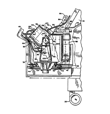
As Fig. 3 shows, the centrifuge 16 includes a
base 42 that supports a plate 45 mounted upon flexible
isolation mounts 44. The flexible mounts 44 structur-
ally isolate the components mounted on the plate 45
from the rest of the centrifuge 16, by dampening vi-
bration and oscillation caused by these plate-mounted
components. The components mounted on the plate 45
make up the isolated mass of the centrifuge 16.
A nonrotating outer housing or bucket 46 is
mounted on the plate 45. The bucket 46 encloses a
stationary platform 48, which in turn supports the
rotating components of the centrifuge 16.
As Figs. 4 and 5 show in greater detail, the ro-
tating components include a centrifuge yoke assembly
50 and a centrifuge chamber assembly 52. The yoke
assembly 50 rotates upon the platform 48 on a first
drive shaft 54. The chamber assembly 52 rotates on
the yoke assembly 50 on a second drive shaft 56. The
rotating chamber assembly 52 carries the processing
chamber 22.
The yoke assembly 50 includes a yoke base 58, a
pair of upstanding yoke arms 60, and a yoke cross mem
ber 62 mounted between the arms 60. The base 58 is
attached to the first drive shaft 54, which spins on
a bearing element 64 about the stationary platform 48.
A first electric drive 66 rotates the yoke assembly 50
on the first drive shaft 54.
The chamber assembly 52 is attached to the s~ ~d
drive shaft 56, which spins on a bearing element ~ 'n'
the yoke cross member 62. The second drive shaft 56
'and the bearing element 68 spin as a unit on ball
bearings 70. A second electric drive 72 rotates the
centrifuge chamber assembly 52 on the second drive
WO 93/12888 PCT/US92/11200
12
shaft.
The first electric drive 66 and the second
electric drive 72 each comprises a permanent magnet,
.brushless DC motor. As Fig. 5 shows, the stationary
platform holds the field coils 74 of the first motor
66, while the yo3ce base 58 comprises the armature or
rotor of the first motor 66. The yoke cross member 62
holds the field coils 74 of the second motor 72, while
the chamber assembly 52 comprises the associated ar
1o mature or rotor.
In the illustrated and preferred embodiment, the
first electric motor 66 spins the yoke assembly 50 at
a predetermined speed of rotation (which will be
called "one omega"). The second electric motor 72
spins the chamber assembly 52 at the same speed of
rotation as the first electric motor 66 in the same
direction and about the same axis as the spinning yoke
assembly 50. As a result, when viewed from a station-
ary (i.e., non-rotating or "zero omega") position, the
chamber assembly 52 spins at twice the rotational
speed of the yoke assembly 50 (which will be called
"two omega").
H. The Dmbilicus Mounts at Zero. One, and Two
Omeca '
As Figs. 6 to 9 show, the fluid circuit 24 join-
ing the processing chamber 22 and the processing con-
tainers 26 comprises separate tubes 74 joined to form
an umbilicus 76. Fluids pass to and from the proces-
sing chamber 22 through these tubes 74.
As Figs. 6 and 7 best show, the centrifuge 16 in-
cludes several umbilicus mounts 78,~ 80, 82, and 84
positioned at spaced apart zero omega, one omega, and
two omega positions on the centrifuge 16. The mounts
78, 80, 82, and 84 secure the upper, middle, and lower
WO 93/12888 PGT/US92/11200
.'
- 13 -
portions of the umbilicus 76, holding it in an in-
vetted question mark shape during processing
operations.
The first umbilicus mount 78 is part of a holder
86 mounted at a zero omega position above and aligned
with the rotational axis of the centrifuge 16. The
mount 78 holds the upper portion of the umbilicus 76
against rotation at this position.
As Figs. 3 and 6 best show, the zero omega holder
l0 86 includes a support frame 88, which is itself at
tached to the isolation plate 45. The zero omega
holder 86 therefore forms a part of the isolated mass
of the centrifuge 16.
A pin 90 attaches one end of the zero omega hold
er 86 to the support frame 88. The holder 86 pivots
on this pin 90 along the rotational axis of centrifuge
16 (as generally shown by arrows in Fig. 3). A spring
92 normally biases the holder 86 away from the rotat
ing components 50 and 52 of the centrifuge 16. A so
lenoid operated latch pin 94 normally locks the holder
86 in the operating position shown in Fig. 6. It
should be appreciated that, alternatively, the holder
86 can be manually locked in the operating position
using a conventional over-center toggle mechanism (not
shown) or the like.
The zero omega holder 86 has a roller member 96
at its opposite end. The roller member 96 rotates on
a shaft 98. The roller member 96 is relieved in its
mid-portion (see Fig. 8) to receive the umbilicus 76
as it enters the cabinet,l8 through an access opening
100.
. As Figs. 7 and.8~best show, the first umbilicus
mount 78 is located next to the roller member 96. The
mount 78 comprises a channel in the holder 86 that
captures an upper block 102 carried by the umbilicus
WO 93/12888 PCT/US92/11200
~1~3~~~ ~ _ 14 _
76. When locked in its operating position (shown in
Fig. 6), the zero omega holder 86 applies tension on
the umbilicus 76, thereby seating the upper umbilicus
block 102 within the mount 78.
In ~ the embodiment illustrated in Figs . 7 to 9 ;
the upper umbilicus block 102 is generally hexagonally
shaped. The mount 78 is also configured as a hexagon
to mate with the block 102. It should be appreciated
that other mating shapes can be used to seat the um-
bilicus block 102 within the mount 78.
Figs. 8A and 8B show an alternative embodiment
for the zero omega holder 86. Like the holder 86
shown in Figs. 7 and 8, the holder 86' is mounted for
pivotal movement on a pin 90' to the support frame 88
(not shown in Figs. 8A and 8B). Also like the holder
86. shown in Figs. 7 and 8, the holder 86' has a roller
member 96' and an umbilicus mount 78' located next to
it. The functions of these components are as previ-
ously described.
Unlike the holder 86' shown in Figs. 7 and 8, the
holder 86' includes a mechanism for clamping the upper
umbilicus- block 102 within the mount 78'. While the
mechanism can vary, in the illustrated embodiment, it
comprises a latch member 250 mounted on pins 252 for
pivotal movement on the holder.86'. Fig. 8A shows the
latch member 250 in an upraised position, opening the
mount 78' for receiving the upper umbilicus block 102.
Fig. 8B shows the latch member 250 in a lowered posi-
tion, covering the mount 78' and retaining the umbili-
cus block 102 therein. As Fig. ~8B shows, the latch
member 250 includes a relieved region that accommo-
dates passage of the umbilicus 76 when the latch mem-
ber 250 is lowered.
A pair of resilient tabs 256 on the latch member
250 mate within.undercuts 258 on the holder 86' to
WO 93/12888 . PCT/US92/11200
~1~~~~~
- 15 -
relensably lock the latch member 250 in its lowered
position. Manually squeezing in the area 260 above
the resilient tabs 256 releases them from the under-
.cuts 258.
The second and third umbilicus mounts 80 and 82
form a part of a~one omega holder 104 carried on the
yoke cross member 62. The mounts 80 and 82 take the
form of spaced apart slotted apertures that secure the
mid-portion of the umbilicus 76 to the yoke cross mem-
ber 62. The mid-portion of the umbilicus 76 carries
a pair of spaced apart resilient bushings 106 that
snap-fit within the slotted second and third mounts 80
and 82 (see Figs. 4.and 7). The slotted mounts 80 and
82 allow the umbilicus bushings 106 to rotate within
them, but otherwise secure the umbilicus 76 as the
yoke assembly 50 rotates. The yoke cross member 62
carries a counterweight 103 opposite to the one omega
holder 104.
The fourth umbilicus mount 84 forms a part of a
two omega holder l08 on the processing chamber assem
bly 52. As best shown in Figs. 15 and 19, the mount
84 comprises a clamp that captures a lower block 110
carried by the umbilicus 76. The clamp mount 84 grips
the lower block 110 to rotate the lower portion of the
umbilicus 76 as the chamber 22 itself rotates.
In the illustrated embodiment (see Fig. 19), the
lower umbilicus block 110 (like the upper umbilicus
block 102) is generally hexagonally shaped. The clamp
mount 84 is also configured to mate with the lower
3o block 110 seated within it. As before pointed out, it
should be appreciated that other mating shapes can be
used to seat the umbilicus block 110 within the-clamp
mount 84.
Further details of the fourth umbilicus mount 84
will be discussed later.
WO 93/12888 ~ PCT/US92/11200
~u~91~ -16 -
The zero omega holder 86 holds the upper portion
of the umbilicus in a non-rotating position above=: the
rotating yoke and chamber assemblies 50 and 52. The
. holder 104 rotates the mid-portion of the umbilic~,s 76
at the one omega speed of the yoke assembly 50. The
holder 108 rotates the lower end of the umbilicus 76
at the two omega speed of the chamber assembly 52.
This relative rotation keeps the umbilicus 76 untwist-
ed, in this way avoiding the need for rotating seals.
C. The one Omeg~a/Two Omeca Drive Control
The processing controller 32 includes an all-
electrical synchronous drive controller 184 for main-
taining the desired one omega/two.omega relationship
between the yoke assembly 50 and the chamber assembly
52. Fig. 10 shows the details of the drive controller
184.
As Fig. 10 shows, both motors 66 and 72 are three
phase motors. Still, double or other multiple phase
motors can be used, if desired. In the illustrated
three phase arrangement, the drive controller 184 in-
cludes a three phase power driver 186. The drive con-
troller 184 also includes a commutation controller 188
for three commutator sensors 190 associated with the
first three phase electric motor 66.
The power driver 186 uses a single.slip ring as-
sembly 192 that serves the second electric motor 72.
The slip ring assembly 192 includes three slip rings
(designated RA, RB, and RC in Fig. 10), one associated
with each pole of the second motor (designated PA, PB,
and PC in Fig. 10). The slip rings RA/RB/RC serve as
a conducting means for electricity. Alternative~con-
ducting means, such as a transformer coupling, could
be used.
The power driver 186 includes three power feeds
WO 93/12888 ~ ~ ~ ~ ~~ ~ PCT/US92/11200
- 17 -
(designated FA, FB, and FC in Fig. 10) connected in
parallel to the three poles PA/PB/PC of first electric
motor 66. The power feeds FA/FB/FC operate the first
'motor 66 at the preselected constant one omega speed
in a closed loop fashion.
The power feeds FA/FB/FC are, in turn, connected
in parallel to the three poles PA/PB%PC of the second
electric motor 72, each via one slip ring RA/RB/RC.
The slip rings serve as a rotating electrical connec-
to tor, transferring power between the first motor 66
(operating at constant speed and in a closed loop) and
the second motor 72.
Since the poles PA/PB/PC of both motors 66 and 72
are connected directly together in parallel, a phase
error will occur whenever the second motor 72 is not
synchronous with the first motor 66. The phase error
causes the two motors 66 and 72 to exchange power.
Depending upon the phase angle between the counter-
electromotive force (emf) voltage vector generated by
the rotor and the voltage vector of the feed line, the
motors 66.and 72 will either transfer power from the
feed lines FA/FB/FC to the rotors (through normal mo-
tor action) cr deliver power from the rotors to a feed
line FA/FH/F.: (through generator action).
More particularly, if the rotor of the second
motor 72 (spinning the chamber assembly 52) moves
ahead of the rotor of the first motor 66 (spinning the
yoke assembly 50), the second motor 72 becomes a gen-
erator, d~:ivering power to the first motor 66. He-
cause the first motor 66 operates in a closed loop at
a constant speed, this power transfer retards the ro-
tor of the second motor 72, causing the phase error to
disappear.
Similarly, if the rotor of the second motor 72
lags behind the first motor 66, the first motor 66 be-
WO 93/12888 PCT/US92/11200
- 18 -
~19~911
comes a generator, delivering power to the second mo-
tor 72. This power transfer advances the rotor of the
second motor 72, again causing the phase error to dis-
'appear. . .
This continuous power exchange applies a correc-
tive torque on the rotor of the second motor 72 that
either advances or retards the rotor of the second
motor 72. In either case, the corrective torque elim-
inates any phase error between the first and second
motors 66 and 72. This keeps the second motor 72 con-
tinuously in synch with and operating at the same ro-
tational speed as the closed loop, constant speed
first motor 66.
This arrangement keeps the chamber assembly 52
spinning, relative to zero omega, at exactly two ome
ga; i.e., twice the one omega speed of the yoke assem
bly 50.
As the following Table illustrates, a drive
controller 184' embodying the above features can be
used to maintain virtual any speed ratio between two
or more motors.
TABLE 1
NUMBER OF POLES SPEED RATIO MAINTAINED
Motor 1 Motor 2 (Motor 2:Motor 1)
2 2 2:1
4 4 2:1
6 6 2:1
8 8 2:1
2 4 3:2
2 6 4:3
4 8 . 3:2
4 6 ~ 5:2
6 2 4:1
6 4 5:3
The drive controller 184 continuously maintains
WO 93/12888
PGT/US92/11200
- 19 -
the desired speed ratio without noisy and heavy geared
or belted mechanical mechanisms or withcut complicat-
ed, sensitive electronic feedback mechanisms. The
.drive controller 184 allows the centrifuge 16 to be
small and lightweight, yet reliable and accurate.
D. ~e centrituqe Drawer
The centrifuge drawer 36 moves the entire iso
lated mass of the centrifuge 16 (carried on the plate
45) across the axis of rotation. The drawer 36 moves
the isolated mass between an operating enclosed posi-
tion (shown in Figs. 2 and 6) and an opened position
accessible to the user (shown in Figs. 1 and 12).
When in its enclosed position, the cabinet 18
shields all sides of the isolated mass of the centri
fuge 16 during operation. When in its opened posi
tion, the isolated mass of the centrifuge 18 is with
drawn from the cabinet 18. The user can access all
sides of the centrifuge 16 either for maintenance or
to conveniently~and quickly load and unload the dis-
posable processing assembly 14.
The centrifuge drawer 36 can be constructed in
various ways. In the illustrate embodiment (as best
shown ir. Fig. 3), the centrifuge base 42 (which sup-
ports the plate 45 upon the flexible isolation mounts
44) rides on tracks 38 within the cabinet 18. The
drawer 36 includes a housing 34 attached to the iso-
lated base 42 for movement on the tracks 38. The
housing 34 has a front handle 40 that the user can
30' grasp to move the entire isolated mass of the centri-
fuge 16 along the tracks 38 between the enclosed and
opened positions.
The controller 32 includes a user-accessible
switch 114 (see Fig. 1) that operates a latch solenoid
116 for the drawer 36. The solenoid 116 normally
WO 93/12888 PGT/US92/11200 _
locks the drawer 36 to keep the centrifuge 16 in its
enclosed operating position (as Fig. 6 shows). Pref-
erable, the processing controller 32 includes an in-
~terlock 118 (see Fig: 14) that prevents operation of
5 the solenoid 196 to unlock the drawer 36 whenever pow-
er is supplied to the centrifuge motors 66 and 72.
The interlock 118 also preferably retains the
latch pin 94 in its engaged position with the zero
omega holder 86 (as Fig. 6 also shows), keeping the
10 holder 86 in its. operating position during processing
operations.
When power is not being supplied to the centri-
fuge motors 66 and 72, operation of the switch 114
moves the solenoid 116 to its unlocked position (as
15 Fig. 11 shows). This frees the drawer 36, allowing
the user to enter the centrifuge 16. Also, the latch-
ing pin 94 withdraws, freeing the zero omega holder 86
for pivotal movement on the support frame 88.
As Figs. 11 and 12 show, as the user opens the
20 drawer 36, moving the isolated mass of the centrifuge
16 to its accessible position, the roller member 96 on
the zero omega holder 86 travels along an interior
ramp 112 within the cabinet 18. As the drawer 36
opens, the ramp 112 urges the. zero omega holder 86
down against the biasing force of the spring 92, guid-
ing the roller member 96 into and through the access
opening 100.
Once the isolated mass of the centrifuge 16 is
in its opened position (as Fig. 12 shows) , the user
can apply a downward force upon the spring biased zero
omega holder 86 to free the upper umbilicus block 102
from the mount 78. Once freed from the block 102, the
.biasing spring 92 pivots the zero omega holder to a
fully upraised and out-of-the-way position shown in
phantom lines in Fig. 12 and in solid lines in Fig.
WO 93/12888 PCT/US92/11200
~.~~~~~~.
- 21 - ~ v
13.
As will be described in greater detail later,
the ramp 112 also serves to guide the roller member 96
'as the drawer 36 closes to return the zero omega hold
s er 86 to its normal operating position.
E. The Two Omega Cbamber l~ssembl3r
As Fig. 13 shows, once the centrifuge 16 occu
pies its accessible position outside the cabinet 18,
the user can pivot the entire processing chamber as
sembly 52 about the yoke cross member 62 to an upright
position convenient for loading and unloading the pro-
cessing chamber 22 (Fig. 1 shows this, too). As Fig.
13 also shows, once in its upright position, the user
can further open the entire processing chamber assem-
bly 52 to further simplify loading and unloading oper-
ations.
1. P~.votinc the Chamber Assembly for
oadi
Figs. 15 to 18A/B/C show the details of the
pivot assembly 194 for moving the processing chamber
52 into its upright position.
The pivot assembly 194 suspends the yoke cross
member 62 between the yoke arms 60. The two omega
chamber assembly 52 carried on the cross member 62
thereby rotates between a downward suspended position
(shown in Fig. 4) and an upright position (shown in
Fig. 15).
When operating, the chamber assembly 52 oc-
cupies the suspended position. The user places the
chamber assembly 52 in the upright position for load-
ing and unloading the processing chamber 22 after hav-
ing placed the isolated mass of the centrifuge 16 is
. in its accessible opened position outside the cabinet.
WO 93/12888 PCT/US92/11200
~~t~391~. - 22 -
The pivot assembly 194 for the chamber assembly
52 may be constructed in various alternative ways.
Figs. 15 to 18A/B/C to 18 show the details of one pre-
ferred embodiment. The Figures show only one side of
the pivot assembly 194 in detail, because the other
side is constructed in the same manner.
The pivot assembly 194 includes.a pair of left
. and right pivot pins 196. Bearings 198 carry the piv
of pins 196 on the yoke arms 60. A retainer bracket
200 secures each pivot pin 196 to the yoke cross mem-
ber 62.
The pivot assembly 194 employs a swinging lock
assembly 202 to control the extent and speed of
rotation of the chamber assembly.52 on the pivot pins
96. The swinging lock assembly 202 includes a rotat-
ing cam 204 secured to the end of each pivot pin 196.
Each cam 204 includes a cut out arcuate groove 206
(see Fig. 16) that ends at opposite first and second
detents, respectively 208 and 210. The groove 206
defines the range of rotation of the chamber assembly
52 on the pivot assembly 194.
The swinging lock assembly 202 also includes
left and right locking pins 212 carried in the top of
each yoke arm 60. Each locking pin 212 has an end key
214 that rides within the interior groove 206 of the
associated cam 204. The opposite end of each locking
pin 212 forms a control button for manipulation by the
user at the top of the upright yoke arms 60.
The user can independently move each locking
pin 212 between an upraised position (shown in Figs.
18A and 18C) and a depressed position (shown in Fig.
18B). The swinging lock assembly 202 uses a spring
218 to normally bias each locking pin 212 toward its
upraised position.
35. When in its upraised position, the end.key 214
WO 93/I2888 PC1"/US92/11200
- 23 -
of each locking pin 212 is captured within either the
first detent 208 or the second detent 210 of the as-
sociated cam 204, depending upon the rotational
position of the cam 204. When captured by either
detent 208/210, the end key 214 prevents further rota-
tion of the associated cam 204. When in ids upraised
position, the end key 214 locks the chamber assembly
52 into either its upright load position or its sus-
pended operating position.
More particularly, when the first detent 208
captures the end key 214 of at least one locking pin
212 (as Fig. 18A shows), the locked cam 204 holds the
chamber assembly 52 in its suspended operating posi-
tion (shown in Fig. 4) . When the second detent 210
captures the,end key 214 of at least one locking pin
212 (as Fig. 18C shows), the locked cam 204 holds the
chamber assembly 52 in its upraised load position
(shown in Fig. 15).
When the user depresses the locking pin 212 (as
Fig. 18B shows), the end key 214 moves out of the
detent 208/210 and into the groove 206, freeing the
associated cam 204 for rotation within the limits of
groove 206. By freeing the end keys 214 of both lock
ing pins 212 from t?:Pir associated detents 208/210,
the user pivots the chamber assembly 52 between its
operating and load positions. Upon rotation from one
detent position to the other, the biasing springs 218
automatically snap the end key 214 of each the locking
pin 212 into the other detent as it reaches alignment
with the end key 214, hereby automatically locking,
the chamber assembly 52 in the other detent position.
In the illustrated and preferred embodiment,
the swinging lock assembly 202 also includes a biasing
spring 220 associated with each cam 204. The springs
220 rotationally bias the cams 204 toward the position
WO 93/12888 PCT/US92/11200
~1~3911 - 24 -
shown in Fig. 18C, where the second detent 210 cap-
tunes the end keys 214 of the locking pins 212. To-
gether, the springs 220 bias the chamber assembly 52
toward its upraised load position.
In this ar-rangement, by depressing both locking
pins 212 with the chamber assembly 52 located in its
downward operating position (Fig. 18A), the freed cams
204 automatically swing the chamber assembly 52 in re
sponse to the springs 220 into its upraised load posi
tion (Fig. 18C).
The swinging lock assembly 202 also preferably
includes a damping cylinder 222 associated with each
spring assisted cam 204. The damping cylinder 222 has
a spring or pressure. operated pin 224 that con-
tinuously presses against an outwardly radially
tapered damping surface 226 on each cam 204. As it
rides upon the tapered damping surface 226, the pin
224 progressively resists the spring-assisted rotation
of each cam 204., moving from the first detent 208 (the
downward operating position) toward the second detent
210 (the upraised load position). The progressive re-
sistance of the.pin 224 slows the pivotal movement of
the assembly 52, as the pin 224 comes to rest at the
outermost radius of the ramp 226 (as Fig. 18B shows),
which amounts to about 100 degrees of rotation from
the suspended operating position. The user then pulls
on the processing chamber 52 to rotate it about an
additional 30 degrees to slip the pin 224 into a re-
. taining notch 21.6 (as Fig. 18C shows). There, the
biasing springs 218 of each locking pin 212 snap the
. end keys 214 into the second detents_210, locking the
chamber assembly 52 in its upraised load position.
With the chamber assembly 52 located in its up-
raised position, the user can simultaneously depress
both locking pins 212. The chamber assembly 52 will
WO 93/12888 PCT/US92/11200
z~~~~ ~r
- 25 -
rotate about 30 degrees, until the pin 224 abuts
against the ramped~portion 217 of the notch 216. The
user is then free to release the locking pins 212
without engaging the second detents 210 and manually
pivot the chamber assembly 52 to free the pin 224 from
the retaining notch 216. Further rotation against the
action of the biasing springs 220 brings the chamber
assembly 52 back to its operating position. There,
the biasing springs 218 of each locking pin 212 snap
the end keys 214 into the first detents 2 08 . of the
cams 204, preventing further rotation out of this po-
sition during processing.
As Fig. 15 shows, a protective cover 221 is
preferably mounted on each side of the yoke arms 60 to
enclose the pivot assembly 194 and associated compo
nents. This protective cover 221 has been removed or
cut away in some of the drawings to simplify the dis-
cussion.
2. O~eninc the Chamber Assembly for
Loadinv
As Figs. i3, l9 and 20 show, when locked in its
upraised position, the user also can open the chamber
assembly 52 for loading and unloading the replaceable
processing chamber 22 in the manner shown in Fig. 1.
For this purpose, the chamber assembly 52
includes a rotating outer bowl 128 that carries within
it an inner spool 130. In use, the inner spool 130
holds the processing chamber 22. The inner spool 130
telescopically moves into and out of the outer bowl
128 to allow the mounting and removal of the chamber
. 22 upon the spool 130.
The outer bowl 128 has a generally cylindrical
interior surface 132. The inner spool 130 has an.ex
terior peripheral surface 134 that fits telescopically
WO 93/12888 PCT/US92/1120(1
. - 26 -
within the outer bowl surface 132 (see Fig. 9) . An
arcuate channel 136 extends between the two surfaces
132 and 134. When mounted on the spool 130, the pro-
~cessing chamber 22 occupies this channel 136. The
spool 130 preferably includes top and bottom flanges
138 to orient the processing chamber 22 within the
channel 136.
The centrifuge assembly 12 includes a mechanism
for moving the inner spool 130 into and out of the
bowl 128. The mechanism can be variously constructed,
and Figs. 19 to 24 show one preferred arrangement.
As Figs. 19 and 20 show, the outer bowl 128 is
coupled to the second drive shaft 56. The inner spool
130 includes a center hub 140. A spool shaft 142 is
secured to the hub 140 by a pin 144. The spool shaft
142 fits telescopically within the open bore of the
second drive shaft 56.
The exterior surface of the spool shaft 142 has
a hexagonal shape (as Fig. 21 best shows). The inte
riot bore at the base 146 of the second drive shaft 56
has a mating hexagonal shape. The mating hexagonal
surfaces couple the spool 130 to the bowl 128 for com-
mon rotation with the second drive shaft 56.
In the arrangement, the inner spool 130 is
movable along the second drive shaft 56 between a low
ered operating position within the outer bowl 128 (as
Fig. 19 shows) and an unlifted loading position out of
the outer bowl 128 (as~Fig. 20 shows). As Fig. 21
best shows, the hub 140 preferably~takes the shape of
a handle that the user can easily grasp to raise and
lower the spool 130.
As Figs. 19 and 20 show, the spool shaft 142
includes an axial keyway 148 having a lower detent 150
and an upper detent 152. The keyway 148 defines the
range of up and down movement of the spool 130 within
WO 93/12888 . PCT/US92/11200
2~ -
the bowl 128.
The bowl 128 includes a detent pin 154 that ex-
tends into the open bore of the second drive shaft 56.
A spring 156 biases the detent pin 154 into the keyway
148, where it rides into and out of releasable
engagement with the lower and upper detents 150 and
152 as the user raises and lowers the spool 130.
In this arrangement, when the upper detent 152
engages the spring biased pin 154 (as Fig. 19 shows),
the spool 130 is releasably retained in its lowered
operating position. When the lower detent 150 engages
the spring biased pin 154 (as Fig. 20 shows), the
spool 130 is releasably retained in its uplifted load-
ing position. Normal external lifting and lowering
force exerted by the user overcomes the biasing force
of the spring 156 to easily move the spool 130 up and
down between these two limit positions.
With the spool 130 locked in its uplifted posi
tion, the user can wrap the processing chamber . upon
the peripheral spool surface 134 (as Fig. 1 snows).
With the spool 130 locked in its lowered posit~an (see
Fig. 19), the wrapped processing chamber 22 is
sandwiched within the channel 136 between .. ~-.e spool
130 and the bowl 128. Rotation of the cha.~~_ assem-
bly 52 subjects the processing chamber 22 to
centrifugal forces within the channel 136.
A locking mechanism 158 prevents the spool 130
from dropping out of the bowl 128 while the chamber
assembly 52 rotates in its downward suspended operat
ing position.
The mechanism 158 includes locking pin 16o fas-
tened to the bowl 128. The distal end of the locking
pin 160 extends out through a passage 120 in the hub
140. The distal end includes a notch 122.
As Figs. 21 and 22 show, a latch member .124
WO 93/12888 - PC1"/US92/11200
28 -
~1~0391~. ~ . _
slides on tracks 126 upon the handle end of the hub
140. The notched distal end of the locking pin 160
passes through an elongated slot 162 in the latch ~~em-
ber 124. Springs 164 normally bias the latch m~::~nber
124 toward a forward position on the handle end of the
hub 140. In this position (shown in Fig. 24), the
notch 122 engages the rear edge 163 of the slot 162.
This engagement secures the spool 130 to the bowl 128.
The latch member 124 is mass balanced so that centrif-
ugal force will not open it during use.
As Fig. 23 shows, sliding the latch member 124
. rearward frees the notch 122 from the rear slot edge
163. This releases the spool 130 from the bowl 128,
allowing the user to lift the spool 130 from the bowl
120 in the manner previously described.
In the embodiment shown in Figs. 19 to 24, the
sliding latch member 124 also forms a part of the two
omega umbilicus clamp mount 84. As Figs. 21 and 23
show, sliding the latch member 124 rearward cpens the
mount 84 to receive the lower umbilicus block 110.
The spring assisted return of the latch member 124 to
its forward position (shown in Fig. 24) captures the
lower umbilicus block 110 within the mount 84. The
biasing springs 164 also hold the latch member 124
closed to clamp the block 110 within the mount during
processing operations.
In this arrangement, the locking pin 160 is
preferably flexible enough to be resiliently displaced
by the user (as the phantom lines in Fig. 24 show) to
free the notch 122 from the rear slot edge 163 without
operating the latch member 124. This allows the user
to lift the spool 130 into its upraised position with-
out freeing the lower umbilicus block (as Fig. 13
shows).
As Figs. 22 and 23 also show, the latch member
WO 93/12888 PCT/US92/11200
124 is preferably vertically moveable within the
tracks to drop the rear slot edge 163 into engagement
against the rear edge 166 of the hub handle. This
allows the user to temporarily secure the latch member
124 in its rearward position against the action of the
biasing springs 164, freeing both of the user s hands
to load the umbilicus 76. Lifting upward frees the
rear slot edge 163, allowing the springs 164 to return
the latch member 164 to its forward clamping position.
Figs. 25 to 27 show an alternative locking
mechanism 158 for the spool 130. In this arrangement,
the second drive shaft 56 includes an undercut
latchway 168. The hub 140 houses a latch pawl 170
carried by a pin 172 for pivotal movement between an
engaged position with the latchway 168 (as Fig. 26
shows) and a disengaged position from the latchway 168
(as Figs. 25 and 27 show).
The hub 140 carries linkage 174 that operates
the latch pawl 170. The linkage 174 has a hooked end
176 coupled to the latch pawl 170 and a pin end 178
positioned in the path of a cam 180 carried by a latch
lever 182. A pin 228 attaches the latch lever 182 to
the hub 140 for pivotal movement between an unlatched
position (shown in Figs. 25 and 27) and a latching
position (shown in Fig. 26).
A spring 230~normally biases the linkage 190 to
maintain the latch pawl 170 in its disengaged position
When the latch lever 18.2 is in its unlatched position.
In this orientation, the user is free to raise the
spool 130 in the manner just described.
With the spool 130 in its lowered position,
movement of the latch lever 182 to the latching posi-
tion brings the cam 180 into contact with the pin end
178. Depressing the pin end 178 in turn moves the
linkage 174 against the biasing force of the spring
WO 93/12888 PGT/US92/11200
~~t~~9~~ - 3° - _
230 to pivot the latch pawl 170 into its engaged po-
sition with the latchway 168. In this orientation,
the interference between the latch pawl 170 and the
~latchway 168 prevents axial movement of the spoo1.130
along the second drive shaft.
When the latch lever 182 is in its latching
position, spring biased pins 232 releasably engage
detents 234 on the latch lever 182. The pins 232
releasably resist movement of the latch lever 182 out
of its latching position. By applying deliberate
lifting force to the latch.lever 182, the user can
overcome the spring biased pins 232 to move the latch-
ing lever 182 into its unlatched position.
In this arrangement, a holding bracket 236 as
sociated with the latch lever 182 locks the lower um
bilicus block 110 within the mount 84 while the spool
130 is locked into its lowered position. In this em
bodiment, the holding bracket 236 opens the mount 84
when the latch lever 182 is in its unlatched position
(shown in Fig. 25) and closes the mount 84 when the
latch lever 182 is in its latching position (.shown in
Fig. 26).
F. Loadinc the Pluid Processing lsrs~embly
Figs. 28 to 31 show the details of loading a
representative processing assembly 14 on the centri-
fuge 16, as is generally depicted in Fig. 1. The rep-
resentative processing assembly 14 includes a
processing chamber 22 formed as an elongated flexible
tube or belt made of a flexible, biocompatible plastic
material such as plasticized medical. grade polyvinyl
. chloride. The umbilicus tubes 74 communicate with
ports 248 to conduct fluids into and out of the pro-
cessing chamber 22.
The user be ins the loadin
9 g process by wrapping
WO 93/12888 PCT/US92/11200
- 31 -
the flexible processing chamber 22 about the upraised
and open spool 130.
As Fig. 28 best shows, the spool 130 includes
one or more alignment tabs 238 on the spool 130. The
spool alignment tabs 238 register with alignment
notches 240 on the processing chamber 22 to assure the
desired orientation of the processing chamber 22 on
the spool 130.
Of course, the ways of aligning the chamber 22
on the spool 130 can vary. In the illustrated em
bodiment, the spool 130 has two alignment tabs 238A
and 2388, and the processing chamber 22 has two mating
alignment notches 240A and 24oH. Alternatively, pins
or other alignment mechanisms can be used.
As Fig. 28 shows, one spool alignment tab 238A
protrudes from the spool surface 134 and mates with
the notch 240A on the processing chamber 22. The oth~
er spool alignment tab 2388 protrudes from a flap 242
that extends from and overhangs a portion of the spool
surface 134.
In the illustrated embodiment, the flap 242 is
hinged. It is movable between a raised position
(shown in phantom lines in Fig. 28), away from the
spool surface 134, and~a lowered position (shown in
solid lines in Fig. 28), facing toward. the spool sur-
face 134. By placing the flap 242 into its lowered
position, the alignment tab 2388 on the flap 242 fits
within a retainer 244 in the spool surface 134.
. In this arrangement, with the flap 242
upraised, the user aligns the notch 240A with the tab
238A and aligns the notch 240B over the retainer 244.
Lowering the flap 242 places the tab 238B into the
retainer 244, capturing the notch 240B between the
flap 242 and the. spool surface 134 (as Fig. 28 shows)
to hold the processing chamber 22 in place.
WO 93/12888 PCf/US92/11200
r
~10391~. ~ - 32 -
Instead of a hinged flap 242, a flap fixed in
the lowered position can be used. In this arrange-
ment, the user tucks the processing chamber 22 beneath
the flap.
As Fig. 29 shows, the user completes the
loading process by overlapping the free ends of the
processing chamber 22 on the opposite side of the
spool 130. A clip 246 captures the overlapping ends,
holding them close against the spool surface 134.
Alternatively, an adhesive tab (not shown) can be used
to hold the overlapping ends of the processing chamber
22 together, as could pins mating with associated
holes in the processing chamber 22.
The user then lowers and locks the spool 130
within the bowl 128 in the manner previously described
to complete the loading process (as Fig. 30 shows).
The user clamps the lower umbilicus block 110 into the
mount 84 in the manner previously described and pivots
the chamber assembly 52 into its downward suspended
position shown in Fig. 4.
The user then snaps the umbilicus bushings 106
into position in the slotted second and third mounts
80 and 82~on the one omega holder 104, as Fig. 4
shows. The user lowers the zero omega holder 86 to-
ward the rotating components 50 and 52 of the
centrifuge 16 to seat the upper block 102 into the
mount 78.
The user closes the drawer 36 and completes the
loading process by placing the tubes 74 into operative
alignment With the pumps. 28 and clamps 30 on the front
panel of the cabinet 18.
The user generally follows a .reverse sequence
~of steps to unload the fluid processing assembly 14.
G. 8ha~ina the Proce~~ina Chamber
WO 93/12888 PCT/US92/11200
33 -
The interior bowl surface 132 and the exterior
spool surface 134 are preformed to create within the
high-G and low-G regions of the processing chamber 22
the specific contours required either to get the de-
sired separation effects or to achieve optimal priming
and air purging, or both.
In the embodiment shown in Fig. 32, the interi-
or bowl surface 132 is preformed with a constant outer
radius (as measured from the rotational axis). In
this arrangement, the exterior spool surface 134 is
preformed with contours of varying radii (also as mea-
sured from the rotational axis) to present the desired
geometry for the low-G region.
For areas where a non-iso-radial geometry on
the high-G wall is desired, the chamber assembly 52
includes an overhanging attachment on the spool 130
extending between the low-G spool surface 134 and the
high-G bowl surface 132. In the illustrated embodi
ment the attachment comprises the hinged flap 242
previously described. As Fig. 31 shows, the flap 242
is clipped, fastened by screws, or otherwise con-
veniently attached to the spool 130.
In this arrangement, all structures that create
the desired contours in both the high-~ and low-G re
gions of the chamber 22 are associated with the inner
spool 130. In this way, changes in the contours to do
different procedures or air purging methods can be
made simply by changing the spool 130.
As Fig. 32 shows, the user can completely
separate the spool 130 from the bowl 128 by pulling up
~on the spool 130 to fully release the spool 130 from
the locking pin 160. Since the spool 130 contains the
desired contour forming surfaces for the processing
chamber 22, the user can easily and quickly remove and
35. exchange a spool having one configuration with a spool
WO 93/12888 PCT/US92/11200
having another configuration.
Various features of the invention are set forth
in the following claims.