Note: Descriptions are shown in the official language in which they were submitted.
~'O 9~ 920 PC~/A1~9~/00070
~" 21Q~1'3'~
MULTI-CyLlNDER ~VvO STROKE ENr~N~s~s~
This invention relates to the construction of the crankshaft and cylinder
block of a two stroke cycle internal combustion engine to prevent the passage of charge
~, air between the respective crankcase compartments of adjacent cylinders of the engine.
Engines opetating on lhe conventional two stroke cycle require the
incoming air charge to the cylinders of the engine to be compressed to an . ,ve
atmospheric pressure in order that the air charge will flow into the engine cylinder
while the exhausl gas from the previous cycle is being discharged. There are two basic
o modes of providing the required degree of compression of the charge gas. one being to
provide a compressor (supercharger) and the other to effect compression oi the cnarge
air in tne engine crankcase by the downward movement of the piston during the exhausl
stroke. Engines employing the latter procedure for compressing the air charge are
commonly referred to as crankcase compression two stroke cycle engines and require the
crankcase to be effectively sealed in order to achieve the required degree of compression
of the air charge ~o be generated by the movement of the piston during the exhaust stroke.
Accordingly, in a multi cylinder two stroke cycle engine operating on the crankcase
compression system requires an individually sealed crankcase compartment to be
provided for each cyiinder of the engine.
2 0 Another characteristic of two stroke cycle engines operating on ~he
CranKCase compression system is that the crankcase can not be used as a reservoir tor
lubricatmg oil. and oil from a pressure circuitry lubrication system can not be
permitted to be directly delivered into the crankcase. Accordingly, the crankshaft and
connecting rod bearings can not normally be of the conventional plain metal type, and are
2, usually of the anti friction type such as ball or roller bearings, which can effectively
operate with minimal lubrication. As such bearings do not form a seal between adjacent
crankcase compartments as is provided by a plain metal bearing, provision must be made
to obtain an effective seai between the cylinder block and crankshaft journals. where the
crankshaft passes through the dividing wall between adjacent crankcase compartments of
3 0 a multi two stroke cycle cylinder engine, to prevent the passage of charge air from one
to the other through the anti-fraction bearing.
- SU~3ST~T~TE SHEET
.
wo 92/14920 PCrtAU92/00070
~ !
2 1 ~ o
The need to provide both a bearing and a seal within the wall separating
adjacent crankcase compartments normally requires the centre distance between
adjacent cylinders to be increased so that the dividing wall is of sufficient width to
accommodate the axial length of Ihe ball or roller bearing together with the a~ial length
of an appropriate seal structure. This results in an increase in the centre distance of
adjacent cylinders which is contrar,v to the requirement of minimising the axial length
of multi cylinder engines to reduce the total weight thereof, to reduce Ihe torsional
vibration in ~he crankshaft, and to reduce ~he space requirement of the engine
compartment of a vehicle, thus contributing to overall reduction in weight of the vehicle,
and the drag co-efficient of the vehicle body.
The above problem has led to a proposed constructions wherein the centre
distance between the cylinder can be reduced and the required bearing and seal support is
, provided by increasing the width of the wall below the level of the cylinders. However,
this construction gives rise to potential problems in manufacture as the portion of Ihe
wall having the increased width can laterally project into a location below the bore of the
! cylinders on one or both sides of the wall. This lateral projection of the wall Io below the
` cylinder can interfere with the machining of the bore of the cylinders and the assembling
of the piston into the cylinder. Both of these operations are preferably performed from
the crankcase end of the cylinders for accuracy and convenience consideration.
2 0 It is therefore the object of the present invention to provide a
construction of a multi cylinder two stroke cycle engine wherein the bearing andadjacent seal in the wall between adjacent crankcase cavities is constructed so as to
minimise the required axial spacing of the cylinders associated with the respective
crankcase cavities.
With this object in view there is provided a multi-cylinder two stroke
cycle reciprocating internal combustion engine, said engine including a cylinder block
incorporating a plurality of cylinders, a crankshaft, a crankcase detachably secured to
the cylinder to define an individual crankcase compartment to communicate with each
cylinder, said crankcase compartments being separated from one another by respective
internal walls, each internal wall supporting a bearing assembly to rotatably support
the crankshaft, said walls being split in a common plane diametral to the crankshaft
axis, whereby a first part of each wall is integral with the cylinder block and a second
part is integral with the crankcase, each said bearing assembly including an outer
~UBSTITUTE SHI~
.~. .
~VO 92/14920 PCT/AU~2/00070
(~;' . .
210~ia~
bearing ring non-rotatably mounted in the respective internal wall co-axial with the
axis of the crankshaft, said first part of each wall being configured so as not lo extend
into the area defined by an imaginary extension of the internal surface of the cylinder on
at least one side of said wall, and the outer bearing ring mounted therein having an axial
extent to project into said area on at least one side of the wall.
Preferably the first part of the wall is configured so as to not extend into
~he area defined by the imaginary extension of the respective cylinders of each side of the
first part of the wall. Further in such a construction the bearing ring preferably
extends beyond the first part of the wall on each side thereof.
Conveniently the bearing ring is of sufficient length in the axial direction
to provide for seal means to be operatively interposed between the bearing ring and the
crankshaft in addition to providing the bearing support for the crankshaft.
, It will be appreciated that as the crankcase is a separate component from
the cylinder block, and is usually removed therefrom during machining of the cylinder
15 block and the assembly of the pistons thereto, the width of the second portion of the wall,
forming part of the crankcase can be of the same width as the bearing ring. It is
preferable for the second portion of the wall to be of the same width as the bearing ring
to provide additional support for the bearing assembly and rigidity of the crankshaft
support.
^~ o In accordance with another aspect of the invention there is provided amu!ti cylinder two stroke cycle internal cornbustion engine having an individualcrankcase compartment for each cylinder formed in a crankcase, said crankcase
including a wall separating two adjacent crankcase compartment, a crankshaft extending
through said wall with a journal of said crankshaft supported in a bearing assembly
2 5 mounted in said wall, said bearing assembly having an outer bearing ring non-rotatably
mounted in said wall with the outer surface of the bearing ring in sealed relation to said
wall, said outer bearing ring having an axial extent greater than the thickness of that
portion of the wall on the cylinder side of the crankshaft axis to provide an internal
annular surface co-axial with said crankshaft journal, and a shoulder on the crankshaft
3 0 located to present an opposing co-axial external annular surface to said internal annular
surface, and seal means operative between said internal and external annular surfaces to
provide a seal between the adjacent crankcase compartments.
8U8STITUTE SHEET -
. . . , . ., ~ . -
. - ~ . . ; . ;; .. . .. .
wo ~2/ l 4920 pcr/A u92/00070
. ~., I
21~1VO
Conveniently the seal means is a seal ring engaging ~he outer bearing ring
in a substantially non-rotational sealing relation and projecting into a peripheral groove
in the crankshaft with close running clearance to provide a seal in the known manner. In
operation, a Silm of the engine lubricant will be established between the seal ring and the
S opposing surfaces of the groove in the crankshaft to create a hydrodynamic form of
Iubrication therebetween.
Alternatively a labyrinth type seal configuration can be provided between
the respective annular surfaces on the crankshaft and the bearing outer ring.
The above construction permits the seal means to overhang the cylinder
bore of the engine associated with the crankcase compartment, within which the seal
means is located, without portir n of the actual wall of the crankcase compartment
overhanging the cylinder bore. Thus the axial spacing between adjacent cylinder bores
in the cylinder block may be reduced by the extent that the seal means overhand the
cylinder bore, without such overhang interfering with the convenient machining of the
cylinder bores and/or assembly of the pistons thereto.
The inventlon will be more readily understood from the following
description of one practical arrangement of a three cylinder two stroke cycle engine
incorporating the two embodiments of the seal arrangement as proposed by the present
invention.
2 0 In the drawings:
Figure 1 is a longitudinal sectional view along the plane of the axis of the
crankshaft of the engine;
Figure 2 is a sectional view along the line 2-2 in Figure 1:
Figure 3 is an enlarged view of the area A ion Figure 1;
2 5 Figure 4 is a view similar to Figure 3 of an alternative seal means.
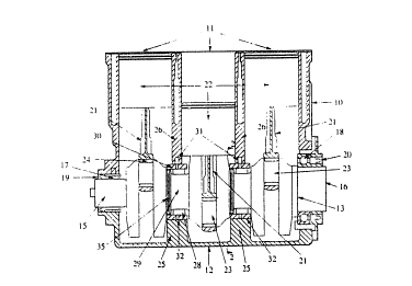
Referring now to Figure 1 of the drawings, the engine comprises a
cylinder block 10 having three parallel in line cylinder bores 11 formed therein, a
detachable crankcase 12 and a one piece crankshaft 13. An engine cylinder head is
normally fitted to the top face of the cylinder block but is omitted from the drawings of
3 0 this specification.
The crankcase 12 and cylinder block 10 have abutting surfaces which lie
on the axial plane of the crankshaft 13 at right angles to the axes of the cylinder bores
11 as seen at 14 in Figure 2. The respective front and rear journals 15 and 16 of the
. . ~,
, .. : .
- . , . .. ~ . . .
. . . .
. . . .. .
. I ! .
~VO 92/ l ~0 PCr~A ~92/00070
~` 2 ~
crankshaft are supponed in respective t~earings 17 and 18 with ou~board oil seals 19
and 20 of conven~ional construction.
Each of ~he connecting rods 21 are connected in the conventional manner
to the respective pistons 22 and to the respective eccentric crankpins 23 of thecrankshatt 13. Conventional split roller bearings 24 are provided between the
connecting rod and the crankpin as is customary in two stroke cycle engines.
The crankcase 12 has formed therein two spaced internal transverse
lower walls 25 which abut corresponding transverse upper walls 26 formed in the
lower part of the cylinder block 10. The abutting lower and upper walls 25 and 26
1 0 divide the space defined by the cylinder block 10 and crankcase 12 in three crankcase
companmen~s each communicaling with a respective cylinder bore. Each of ~he abutting
walls 25.26 also define a bearing bore 27, in axial alignment with front and rear
crankshaft bearings 17 and 18. receiving the respective roller bearing assemblies 30.
Each of the roller bearing assemblies 30 are of the known split type so that they may be
1 5 assembled about the respective intermediate journals 29 of the crankshaft 13.
The two sections of the split roller bearing assemblies 30 are held in the
desired assembled relationship by being clamped between the crankcase wall 25 and
cylinder block wall 26 so that the outer race 32 of the bearing assembly 30 is held
.~ against rotation. In addition a locating dowell 35 is provided to be received in respective
2 0 aiigned aDertures in the cylinder block and outer race 32 of the bearing assembly. ~-
. As can be clearly seen in Figures 3 and 4, the cylinder block wall 26 is
substantially narrower than the complementary crankcase wall 25. The cylinder block
wall 26 has a thickness equal to the thickness of the wall 28 between the cylinder bore
11 measured at the longitudinal axis of the cylinder block. Accordingly the cylinder
2 5 block wall 25 does not extend at any point into a location immediately below the cylinder
; bore 11 thus providing unobstructed entry of a piston into the cylinder bore from the
lower or crankcase side of the cylinder block 10. In contrast, the crankcase wall 25 is
of a substantially greater thickness and extends below each of the cylinder bores 11 on
either side of the wall 28.
3 0 The outer race 32 of each bearing assembly 30 has a greater axial length
than the cylinder block wall 26. and thus projects from either side thereof. and is
substantially equal to the width of the crankcase wall 25.
- S~JBSTITUTE SHEE~
- : . . . . .... .... . :
~ - ~- - : - :
wo 9~/149~0 PCI/A~!92/~0070 1.
2 ~ ~ :
The outer race 32 also has a greater axial length than the intermediate
journal 29 of the crankshaft and of ~he rollers 28 of the bearing assembly 3C, which are
substantially the same length as the intermediale journals 29. As seen in Figures 1 and
3, the rollers 28 are offset with respect to the outer races 32 and the walls 25,26
s respectively, so that the spigot 31 formed as part of the crankshaft 13 may extend co-
axially into the outer race 32. Thus the rollers 28 of the bearing assemblies are located
axially between the shoulder 36 of the crankshaft and the face 37 of the spigot 31.
As seen more clearly in Figure 3, each spigot 31 is provided with a
plurality of co-axial parallel grooves 38 in the peripheral surface thereof with the
1 0 peripheral surface of the ridges 39 between said grooves in close running relationship
with the internal face of the outer race 32 of the bearing assembly. This configuration
forms a conventional labyrinth type seal to substantially prevent the transfer of air
from one crankcase compartment to the adjoining cornpartment.
It will be noted that the outer race 32 of the roller bearing 30 projects
1 5 beyond the wall 26 of the adjacent cylinder bore 11 so as to lie in the line of the piston
as it reciprocates in the bore. However, as the outer race is not in position within the
cylinder block during the machining thereof, nor during the introduction of a piston in
~he cylinder bore during assembly, the outer race does not interfere with ~he free
passage of the various tools, through the cylinder bore, such as are required in the
2 0 forming and honing of the cylinder bores.
This construction enables the centre distance between the cylinder bores
to be reduced without necessitating a similar reduction in the axial length of the
combined bearing and seal areas of the intermediate bearings supporting the crankshaft.
In the above description, reference has been made to roller bearing
2 5 assemblies supporting the crankshaft, however, it is to be understood that other forms of
anti-friction bearing may be used, including ball bearings. In some engines the bearing
may be of the plain slipper bearing type commonly used in engines. Also other types of
seal construction may be used as an alternative to a labyrinth seal. One form ofalternativa seal means would be a single split outwardly expanding ring similar to a
3 0 conventional piston ring as is shown in Figure 4.
In this construction a peripheral groove 40 is provided in the spigot 38
on the crankshaft 13 at 3 location to be positioned within the outer bearing race 32 when
assembled. The seal ring 41 is of a split outwar~ly expanding type so that it must be
SUBSTITUT~: SHEET
. . . .
.
wo 92/14920 PCT/AI I92/0007~
~ 2 1 ~
compressed from its free diametral size to be received in the outer bearing race 32, as
in the manner of a piston ring. The seal ring 41 is of an axial length to be received in the
peripherai groove 40 with a controlled clearance between the walls oi the groove and the
diametral faces of the seal ring, so that hydrodynamic lubrication conditions will exist
5 therebetween when Ihe crankshaft is rotating and the seal ring 41 is stationary with the
outer bearing race 32.
~` A further form of seal that can be used between the crankshaft spigot 38
and the outer bearing race 32 is a convention flexible seal as commonly used in
conjunction with a rotating shaft or member and as generally shown diagrammatically at
10 19 and 20 in Figure 1.
.
. ,:
,:
. ''~
SUBSTITUTE SHEET -
~;'. ,.~ - . . ;..... ..
... , . . . . . ` .,: .. : .
; . ., . .: . . . .
-. . - . , . ~ . ~ . . .
.
: - ~ . . . . .. - -
~ : - . . . . . .. . :