Note: Descriptions are shown in the official language in which they were submitted.
NO 92J14408 - 1 ~ PC~/EP~/00294
Spiral implant for organ pathway~
The invention relate~ to implant~ for organ
pathway~, preferably for blood ve~sel~, whose secondary
shape i~ fo~med either from a primary wire ~piral made of
metal or a prLmary tube made of synthetic material by
twistin~ or winding, the secondary shapP bei~g extended
for in~roduction and being reformad in as~ociation with
placemen~ in the organ;
In interventional radiology, metal spLrals fbr
vessel occlusion have, for more than 10 year~, been
Lmplanted ~lsing catheters. Spirals of this type are
described repeatedly i~ tha literature. In Radiology
136;230-231 ~July 1980), N. Ca~taneda-Z~niga et al.
describ~ an L~proved form of the so-called Gianturco
spiral~r which can be introduced u~ing cath~ter~ mad~ of
polyurethane or polyethylene. The primary spiral is
formed by appropria~e techniques in~o a ball or ~ secon-
dary spiral. In order to be able to implant the spiral in
its secondary shapa, the latter i3 extended by drawing up
the primary spiral onto a guide wire. When Lmplanting by
means of a catheter on the guide wire, a further dis-
placeable spiral is arranged on the guide wire, which
spiral serves to push ~he implant, i.e. the prLmary
spiral, out of the catheter and to push it off from the
guide wire, so that the ~econdary shape is re~rmed and
the secondary spiral or the ball re~ain~ in the vessel
which is to be oc~luded.
In Am. J. Roentgenol. 129: 795-798 ~November
1977) J. Andersonf S. Walace and C. Gianturco describe
the advantages of being able ~o replace the ~piral before
finally ca~ting it o~f. Howaver, their helical cork~crew
connection has the di~ad~antage that there is the danger
of the vessel being per~orated by the sharp e~d of the
spiral. In a~dition, the spiral can be di~placed by
ro~ation while disconnecting. This is also suggeqted by
the numerous complications in the animal experiments.
In Radiology 138; 37-46 (Ja~a~y 1981), M.J.
M~zer and coworkers describe the disad~antages of the
'
' '
r ~ 7 i~ 4 ~ ~ ~
rela~i~ely high degree~ of deformat~on, in~o a helical
spring body, such that the spring body, on the
application of an external force, can be el~s~ically
reformed into a straight wira ~piral and, on partial
ce~sat~on of thi~ ~orca, assume~ a knot-~haped
con~iguration.
It is the ob~ect of the pre~ent in~ention to
improve the constructional configura~ion of the i~plant~
and of the insertion wire in such a way that the pos-
sibility exi~ts, be~ore finally detaching the implant5fr~m the auxiliary mean~ employed for the in er~ion, of,
~E:P~I~T SH13
- 7 ~ ; ` `: - : :
.
- : ., : ` . . : :: :
WO 92J14408 - 2 - PCT/EP92/00294
known technique and refer to failur~ arising from
incorrect choice o~ the si2e of the secondary ~piral and
to the ri~ks o~ using unsuitable stripping devices.
A device for occluding arterie~ is described in
~D-A-223 065, which de~ice comprises a cardiac or angio-
graphic cathe~er, with a prepared point, a pu~hing
element (pusher), an occluding body and a core wire, on
the front end of which wire the occluding body i~ slid on
and is detachably secursd. The core wire run~ movably in
th~ intarior of the pu~hing ~lement and can ba i~ro
duced, together with the slid-on oc~luding body and the
pushing element, beyond the opening of the cathetsr
further into the ar~ery in such a way that ths occluding
body remains on the core wire and i~ also con~eyed by
15 ~hi~ wire outside of the catheter. By keeping a firm hold
on the core wire and by further pushing of the pushing
element, the occluding bo~y can be stripped off the core
wire. This can take place by retracting the core wire
into the pushing elQment. ~he occluding body i provided
with a textile fibre material over its whole length and
over i~ whole periphery. It possesses a sleeve-shaped
part at its po~terior end into which the core wire can be
introduced in such a way tha~ the occluding body can be
detached eficiently from th~ core wire usin~ the pushing
element.
An occluding body suitable for the intra-arterial
and intravenou~ occlu~ion of blood ves~els, is kno~n from
DD-A-158 084, in which occluding ~ody a wire spiral is
formed, with the use of relatively high degrees of defor-
mation, into a helical spring body, such that the spring
bod~, on the application of an external force, can be
eLastically re~ormed into a straight wire spiral and, on
partial cessation of this force, assumes a knot-~haped
configuration.
It is the ob~ect of the present invention to
Lmprove the constructional configuration of the Lmplants
in such a way tha~ the possibili~y exists~ be~ore finally
detaching the implant~ from the auxiliary mean~ empioyed
' ~
`
;
.
2 ~ 9
- where appropriate, recovering these implan~s once again
or elss altering their po~ition in the organ pathwa~.
This object is achieved by an imp}ant for org~n.
pathway~ which i~ formed from a primary spiral made o~
metal or a primary tube made of elaatic ~ynth~tic
material, in which the anterior end o~ the pri~ary ~piral
or of the primary tube i5 closed and the pos~erior region
is ~orm~d a3 a clamping ~ea~ for a guide wire, and ~h~
L~plant pos~e~se~ a secondary shape of increa~ed external.
diametQr, which shape can be ex~ended by sliding- th~
primary spiral or primary tube on~o the guide wire hnd
reform~ on pulling out the guide wire or o~ pushing off
from the guide wire by rastitutory forces present in.the
material, characterize~ i~ that, at a distance of 0.5.mm
to 2 mm from the posterior end o the primary ~piral or
of tha primary tube, it~ cro~s-~ectio~ is modified for a
distance of 0~01 mm to 10 mm by diminution o the inter-
nal diame~er in at leas~ one radial direction. ::
In addition, the in~ention includes a device for
inserting these implant-~ into an organ pathway, having an
insertion catheter, a stripping element and a guide wire
for the Lmplant, where the force required to displace ~he
primary spiral or the primary tube and to overcome the
clamping force with the guide wire ~er~ing as an in~er-
tion aid is 0~5 N to 10 N, preferably 1.5 N to 3 N.
REPL~E~E~T S~E~T
...,, . ' '
, . , ~. . ., : ., ~ ,
..
~ 7 `~ 9
wo 92/14408 - 3 - ~ PCT~P92/00294
for tha in~ertion, of, where appropriate, recovering
these implants once again or else al~ering their po~ition
in the organ pathway.
Thi~ object is achieved by an implant for organ
pathways which is formed from a primary spiral made o~
metal or a prLmary tube made of ela~tic synthetic
material, in which the anterior end of the prL~ary ~piral
or of the primAry tube i~ clo~ed and the po~terior region
i~ formed as a clamping seat for a guide wire, ch~rac-
terized in tha~, at a dis~ance of 0.5 mm ~o 2 mm from theposterior end of the primary spiral or of the primary
tube, its cross-section is modified for a distance o~
O.01 mm to 10 mm by diminution of the internal diameter
in at lea3t one radlal direction, 50 ~ha~ the force
required to displace the primary spiral or the primary
tube a~d to overcome the clamping force with the guide
wire ~er~ing a~ an insertion aid i~ 005 N to 10 N, the
implant has a secondary shape of increased external
diameter, which ~hape can ~e extended by ~he primary
spiral or the primary tube being slid onto the guide wire
and reforms on pulling o~t th~ guids wire or on pu~hing
of~ from the guide wire as a result of restitutory orces
presen~ in the material. Force3 between 1.5 N and 3N are
preferred.
The primary 3pirals having diameters of 0.2 mm to
3 mm, preferably 0.4 mm to 1.5 mm, are wound from metal
wire having diam0ters of 0.Q6 mm to 0.6 mm, preferably
O.1 mm to 0.4 mm, and the secondary shape is formed
subseguent}y. ~owever, the shape can al~o be for~ed at
the same time as the primary spiral i5 being wound.
Suitable materials for the implants having a primary
spiral made of metal are surgical steel wire with spring
propertieq, corrosivQ or non-corro~ive ~pring steel wire
and steel wire made of non-precious metals, which is
coated with corrosion-resistant metals such as tantalum,
titanium, platinum or gold, or ceramic material3. The
wire can have a round, oval or rectangular cro~s ~ection.
. - . . . ~ ~ , . ..
.
-
.. . ~ ~. . . .
~O 9~/14408 ~ 4 ~ ~ PCTfEP92/00294
~ he pr~ary tube3 for implantc~ are prepared from
medically compatible elastic thennopLa3tic polymers, such
as polyurethane homopolymers or copolym~r~, polyolefin
copolymer~ or silicone elastomer~. Re~orbable polymer~,
S such a~ aliphatic polye~ter~, e.g. polydio~anone, ars
also suitable, and the secondary spiral shape is formed
subsequently. The wall thickness of the prLmary tube~ can
ba 0.08 mm to 0.8 mm, and the diameter of the primary
tubes 0.3 mm to 3 ~m. The constriction of the cros~-
section for achieving a clamping seat, in the ca~e ofprLmary ~ubes, can also take place by parallel elongated
slo~s being cut in o~er the circumference of the t~be,
and longi~udinal strip~ of the polymer material being
per}llanently deformed inward~ b~ being pre~-4ed in. The
ad~antage of this configuration of the cro~s-sectional
con~triction for producing a clamping seat on the guid~
wire is that the 1OAg1tUdina11Y extending ~ection~ which
ha~e been formed exhibit an enlarged contact surface on
the guide wire.
~h0 length o~ the primary shape_, i.e. o~ the
primary ~pirals or primiary tube3, can be 10 to 500 mm,
pre~erably 10 mm to 200 mm.
It is a characteristic of th~ implants according
to the invention that the ~econdary qpiral shape can be
rever~ibly extended by sliding the prima~y spiral or the
primary tube onto a guide wire, who3e internal diameter
i~ omewhat smaller than ~he internal dia~ter of th~
prLmary spiral or ~he prima~y tub~ in the non-modified
part~, and that the s~condary ~hape is reformed on
pulling out the guide wire or on pushing off from the
guide wire a~ a result o~ restitutory force~ present in
the material. An elastic spring behaviour of this nature,
and the restitutory forces re~ulting from it, are ba~ed
on ~he properties of the selected materials. The spring
action can, for example, be achiaved by heating the
material, which has been con~igured in~o the desired
shape, and 3ubsequently cooling (quenching) it rapidly.
The spxing action of thermoplastic polymer~ frequently
. . .- . . .
- . ..
. . ~ . .. ...
. . . ..
-
21~4119
~0 92J14408 - 5 PC~/EP92/0029
depends on the formation o~ par~icular cry~talline
structures, or on the freazing in of ~tre~es in the
material during shaping. The mea~ures for e~tabli~hi~g
the modulus of ela~ticity of the material nace~sary for
th~ r~versible extension, and the selection of the
materials which are suitable for this, are known to the
perqon skilled in the art and do not pre~ent him with any
difficulties.
By means of the part formed with a modified
cross-section in the vicinity of th2 rear end of the
primary shape of the implants, a clamping seat is
achieved of the pr~mary shape, tha~ i~ approximately the
extended ~econdary shape on the guide wire, in as~oci-
ation with which, however, ~he clamping force is not so
great that displacement of the primary shape on the guide
wire and complete withdrawal of the guide wire, or
~tripping from the guide wire by means of a stripping
elemen~ no longer possible.
The placement of the implant is effected using a
de~ice having an inser~ion catheter, a stripping element
and a guide wire for the Lmplan~, the guide wire being
provided with a conical point and posse~sing, immediately
after the point, either an an~ular groove or a circum-
farential beading, i~ order to achieve a particularly
high cl2mping effQCt between the pocterior region of the
implant, with reduced internal diameter, and the anterior
regio~ of the guide wire.
Fsr insertion into an organ path~ay, the guide
wire, with the stripping element slid onto it and the
primary shape of the extended implant ~lid on in fron~ of
the element, ic placed inside a oathQter. ~ith a solid
cross section, the diame~er of the guide wire3 can be
0,07 to 0.7 mm. The ability to reposition the implant is
given by the sta~ic friction of the part wi~h the modi-
fied, preferably reduced, cro~q-section on the guide wire
being 2 to 5 times, pre~erably 2 to 3 times, greater than
the force which is necessary in ordex to stretch once
again the secondary shape, which to a large ex~ent has
: "
,, : . :
- - . . , ~,: . . . :
2 ~
WO 92J1440E~ - 6 - PCT~E:P92~00:~94
been complet~ly formed in the organ pathway as the re3ult
of partial ~tripping from the guide wira, by retracti~g
it into the insertion cathe~er. The s~lected uppor limit
of the clamping force en~ures that, in the event of
unwanted catching ~f the implant in the wall of the organ
pathway, damage to the lat~er by too great a withdrawal
force i~ avoided. ~he clamping seat of the primary shape
of the implant on the` guide wire is achieved ~y the
cros~-section of at least one to several turnæ of the
primary spiral being modified by constriction of th~
di~mater of the prLmary spixal, or by formation o~ an
oval cross-section whose smaller diameter is ~maller than
the ex~ernal diameter of the guide wire. The desired dif-
ferenca between withdrawal force into the insertion
catheter a~d the force for overcoming the clamping seat
of the primary shape on the guida wire can, with the
given modified cro~s-section of the prima~y ~hape, alRo
be brought about by using a guide wire with a friction-
increasing ~urface con~iguration, for example a roughened
surface, in the anterior region, with a circumferential
beading, or by mean~ of an annular groove in the guide
wire in which the modified, preferably constricted,
cross-section at least partially engages.
The device described above pe~mits reliable
placement of ~he Lmplant according to the in~ent~on in an
organ pathway, going through ~he following step~:
a) advancement of the catheter, in who~e inner lumen
the implant is located in extended condition on the
insertion wire, in~ide tha organ pathway into the
vicinity of the site where the implant is to be
located,
b) di~placement of the insertion wire, with the implant
located on it in extended hape, to the intended
sit~ for the location,
c) formation of the secondary shape of the implant by
withdrawing the guide wire or by pushing forward the
stripping elemen~,
~ . ,: . .
':' ;' ' '~'.. ': ' ' ' '
,: : ..
: .
2 l a ~
~o 92~14~08 _ 7 _ ~ Pc~/~Pg2/Oe294
d) further withdrawaL of tha catheter and of the guide
wire, or pu~hing ~orward of the ~tripping el~ment,
until only the anterior point of the guide wirs i3
heLd in the clamping seat in the po~erior region
of the primary spiral or the primary tube,
e) correction of the position of the Lmplant, or, i~
neca~3ary, withdrawal o~ the implant into the
catheter,
f) stripping-off o~ the implant from the guide wire a~
~he sita intcnded for it in the organ pathway u~ing
the stripping element.
Th~ ~econdary shape~ of the lmplant~ according to
the invention can exhibit varying ~OrmB, in each ca~e
accordLng ~o the ~pecial i~tended ef~ect i~ the organ
pathway.
As a prosthe~i~ for an organ pathway, a
cylindrical form is preerred i~ wh~ch the external
diameter of the cylinder must be at lea~t a~ large as the
inte~nal diam~er of the organ pathway to be supported,
in order to guarantee Yecure plac~ment. In order to
re~uce the ri~k o~ throm~osi~, it is preferred, in this
mode of applicatio~, to heparinise the ~urface o~ the
implant. In ~he case of implants made of polymer~, the
chemical bondi~g of heparin to t ~ polym~r presents no
problem3y and is known to the per~on skilled in the art.
I~ the ca~e of Lmplants mad2 of m~tal, th~ b~nding of the
hsparin can necessitate the application of a thin
adhe4ive layer of a medically compatible polymer which i~
capa~le of chemical bonding. Sinc~ the suitable polymers,
such as, for example, polyvinyl alcohol, silicones, or
copolymer~ with heparin binding groups based on poly-
urethane~ or polyolefins, possess film-forming
properties, the polymsrs can be applied either from a
disper~io~, emulsion or solu~ion in organio olvents, and
the film can be formed by evaporatin~ of~ the liquid
medium.
In order to configure the open in~er cross-
section of prostheses o~ this type to be a~ large a~
: -. ~ . , . . :. ,. . - . : -
, ~ , , ,. . ,
- , . . ~ . , ,
2~0~9
~O 92/14408 - a Pc~Pq2/002s4
pos~ible, the primary spiral or the prLmary tube of the --
Lmplant can ha~e an oval cros~-~ection, and the
cylindrical secondary shape can be ~o formed that the
surface~ with the larger radius of curvature of th~
primary shape~ are arranged alongside each other in the
secondary shape, and form the outer surfaee of the
secondary shape.
~ owever~ a contrary effect of the implant3 i~
frequently de~ired; organ pathway~ are to be constricted
or occluded by the implant. In order to achieve this with
a cylindrical secondary ~hape, either the diamater can be
formed to be correspondingly small, or ~ cylindrical
~piral can be wound in which turn~ of ~arying diameter
alterna~P so that ~he internal diameter o~ the ~econdary
shape is variably formed in the lengthwi3e axi~ of the
spiral, with individual turn~ or several turn of the
minimum possible radiu~ of curvature. A con~triction of
an organ pathwa~ can also be achieved ~y means of a cone
or a double cone with the larger diameter at the ends o~
the secondary shape. In thi~ way, flow~ in ves~el~ (via
cathetery) can be throttled. In this context, the minLmum
in~ernal diameter ~hould not be less than 4 mm, if the
vessel must remain open. (One possible application i9
pul~onary banding in children with left-right shu~t).
For an o~clu3ion, a shape which i~ here desig-
na~ed a helix is par~i~ularly suitable. In thi~ case, th~
primary shap2 i~ wound helically, with the primary shape
being bent of~ in the cen~re at right angle~ to the halix
and, at a distance from the fir3t helix, a ~econd helix
being formed parallel to it, which second helix can,
where neces~ary, also have a ~maller or larger diameter.
The primary shape between the two helical elements can
al~o be wound a~ a ~piral, in order to provide the
~econdary shape with greater stability in the direction
of the lengthwi~e axis. When being u~e~ for occlusion in
as30ciation with a cardiac septum defect, this secondary
~hape can yield ela~tically ~o the alteration~ in wall
thickness at each heartbea~.
' `~ -
. . ,. . . : ., ; .. :
~O 92~14408 - 9 - PCT/~P92/00294
In order to increase ~he rigidity of the external
turn~ of the helix or of the double-cone sha~e, the WirQ
used ~o prepare the primary spiral or primary shape can
al~o, ins~ead of a relatively large round cro3s-section,
have an oval o~ rectangular cro~ ection.
Since, particularly in perinatal u~e, the extar-
nal diameter of the in~ertion catheter should be a~ small
a~ pos~ibler and consequently the spiral diameter of the
secondary 3hape mu~t necessarily al~o remain 3mall, thi~
can lead, in the ca~e of larger organ pathways to b0
occluded, to problems of s~a~ility in as~ociation wi~h
arrangement and locs~ion, with the danger of incompleta
occlusion or o~ di~location. In such a case, it i~
particularly preferred to locate double cones a~ implant~
in the organ pathway in a tand~m arrange~en~. For carry
ing out the location, ~wo ~condary shape , in each ca~e
~ormed as a double cone, are arranged behind one another
in extended form on the guid~ wire. Th~ first double cone
with a per~anent inner lumen i~ implanted, and ~ubse-
quently the second im~lant, in extended form, i~ pu~hedso far forward that the a~terior end pro~ects beyond the
first double cone to be L~planted, and par~ially unroll~.
By furthar withdrawal of the guide wire, while the
stripping element is sta~ionary, a cen~ral part of the
doublQ cone i~ deposited i~ the inside of the first
double cone in more or 10~s axtended ~orm~ and the end of
~h~ ~eoond double cone out~ide the firs~ double con~
unroll~. The elastic ~orce of the second implant, which
i5 ~ill extended in tha inner lumen o~ the first double
cone, pulls the fir3t implant as tightly together as
pos3ible and anlarge~ ths external diameter of the ends
of the dou~le cone, and incxea~es tho contact pres~ure on
the organ wall. At tha same time, the inner lumen i~
additionally closed. The minLmum external diameter i~
association with catheter occlusion i~ only 1.3 to 2.3 mm
(4 F to 7 F) in thi~ technique, ~o that this implantation
technique can also be employed with neonate or premature
babies. ~f the smalle~t im~lant is ~upplied in a normal
~,,. . . ~ .
'-: ' ' . . , '' . ' :~' . : : ',
.. : ' - '
21~119
WO 92/14408 - 10 - Pc~JEp92/oo294
cannula, the ~mallest external diametex then amount~ to
only 1 mm, and thu3 permit~ use in a relati~ely ri~k-free
manner even at the prenatal tage, e.g. for aneuris~al
occlusion .
Since a thrombotic e~fect i~ de3ired in associa-
~ion wi~h ~he occlusion of an organ pathway, the surface
o the~e Lmplant~ i9 not heparinised but, on th~ con-
trary, is given a coa~ulation-promoti~g configuration.
This can take plac~ by coating ~he ~urface with metal
0 particl8s I Rilicones~ polytetrafluoroethylene~, m~dically
compatible rubber la~ice~, or wi~h medically compatibla
polymers which promota b~ood coagulation. ?
For plugging cavities and ve~sels, a secondary
shape of the Lmplan~ i~ i~ partieular suitable which
15 pos3e~es several loops lyi~g behind each other in tha
form of horiæo~tal figures of eight.
The in~ention is described below in still more
detail with reference to the illus~ration.
Figuro 1 3hows diagrammatically a cylindrical
secondary shap~ of the implant which, with a ~mall spiral
diameter, can be used to occlude a narrow organ pathwa~
or, with a larger diameter, can be used a3 a prosthe3is
for keeping an organ pathway open.
Figure 2 show~ diagrammatically in longitudinal
sec~ion a par~ of the po3terior end of the prLmary shape
of the implant spiral from Figure 1.
Figure 3 show~ diagrammatically a cylindrical
secondary shape o~ the Lmplant spiral whose primary ~hape
differ~ from the primary ~hape in Figure 1 in it~ cro-qs-
30 sectional shape. ;~
Figure 4 show~ diagrammatically a cylindrical ~ :
secondary shape of the implant with spiral ~wists of
varying diameter.
Figure 5 shows diagrammatically a conical shape : -
of the implant.
Figure 6 .~0W8 diagrammatically an implant in the
form of a d~uble cone. ~.
. ~
2 ~ 9
11 --
In Fig~re 2, the pos~erior end of the primasy
shape of th~ implant from Figure 1 is reprodsced in
enlarged form. Th~ i~terna} diameter of the p~imary
spiral 2, which i~ wound out o~ me~al wire ha~ing spring
properties, i9 constricted at a short distance from the
pos~erior end 5 by mean~ of turns 6 which have a smalIer
diameter. If the primary spiral 2 is sli~ on~o an inser-
tion wire whose external dlame~er is ~omewhat larger than
the modlied internal d~axe~er 7 of tha primary ~piral
2, the clamping seat of the extend~d secondary shape on
th~ ins~rtion wire, which seat i~ d~ired for the re-
positionability, is formed.
The cylindrical spiral 1 reprecented in Figure 3
i~ ~ormed from ~ primary shape 2 whose cross-section 3 is
R~PhaCE~ENT 5HEET
: . . . .,. : . . .. . - .
~a 92~1440~ PcT/~ps2/oa2s4
Figures 7, 7a and 7b show the L~plant shape of
the so-calle~ double helix and double ro~ette from th~
side and from behind.
Figure 8 show~ diagrammatically a preferred
embodiment of the anterior end of an insertion wire ~sr
implanting the spiral~ accbrding to the in~ention.
Figure ~ shows the anterior end of an in~ertion
catheter in longitudinal ~ectio~.
Figure 10 show3 in cro~ ection the end of a~
1~ insertivn cathe~er which wa~ repres~nted in Figure 9.
Figure 11 show~ diagrzmmatically, in ~equence a
to e, the individual ~teps invoLved in locating a~
implant according to the invention in an organ pathway.
The Lmplant ~hown in Figura 1 ha~ the ~econdary
shape 1 of a cylindrical helix or ~piral, the helix 1
it~elf being composed of a wire ~piral 2 (primary shape)
made of spring metal. The modification of the cross-
~ection 3 of the primary ~piral 2 at the po~terior end i~
not ~how~ in ~hi~ figure. The anterior end 4 o the
primary ~piral 2 i~ clo~ed in order ~o ensure that~ on
extending the ~econdary ~hape on the in~ertion wire, the
primary spiral 2 cannot be drawn 40 far up the insertion
wire that the latter pro~sct~ bayond the end of the
primary spiral 2.
In Figure 2, the po~t~rior end of tha primary
shape oi ~he i~plant from Pigure 1 is reproduced in
enla~ged iorm. The internal diameter of the primary
~piral 2, which is wound out of me~al wire having spring
propertie~ constrictad at a short dis~ance from the
po~terior end 5 by means of turn~ 6 which have a smaller
diameter. If the pri~ary spiral 2 ~9 slid on~o an inser-
tion wire whose external diameter i~ somewhat larger than
the modi ied internal diameter ~ of the primary spiral
2, ~he clamping seat o~ th~ extended secondary shape on
the insertion catheter, which seat is desired for the re-
positionability, is formed.
The cylindrical spiral 1 represen~ed in ~igure 3
is formed from a primary sh~pe 2 whose cross-~ection 3 i5
. ,., ~ . ..... . . . . .
. " - .
'~ : - ' ', . , , :
`: : ' : ` .
:: " `
- 12 -
oval. The anterior end 4 o the p~imary spiral 2 i~
closed. $his shape is particularly ~uitable a~ a pro~-
thosis for organ pa~hways because, a~ compared with the
shap~ shown in Figure 1, a ~omewhat larger free internal
volum~ of the prosthesi3 remains.
Figure 4 ~hows a cyiindrical shape of the secon-
dary ~hape 1, which was formed from a primary spiral 2.
The anterior end 4 of the primary spiral 2 is closed. In
order ~o form the i~plant to be particularly ~uitable for
occluding organ pathway~, the secondary shape 1 posse~e~
turns ~, 10, o different diametPr, which alternate with
each other. Tha turns o the implant ha~ing the larger
diameter 9 serve to support the ~mplant again~t the wall
of ~he organ pathway and the t~rns 10 ha~ing the small~r
~5 diameter redu~e the free in~ernal vol~me of the Lmplant
and ~hereby promote occlu~ion through thrombo~is.
Figure S shows the configuration of a conical
secondaxy shape 1 from a primary ~piral 2. In order to
simplify the positioningr and retraction into the inser-
tion catheter, of a
REPha~EME~T S~æ~T ~ :
. :
;
', ,:
~' :- ':,.
2 1 0 ~
WO 92~14408 - 12 - PC~EP92/00294
oval. The anterior and 4 o the primary spiral 2 i~ -.
clo~ed. Thi~ ~hape i~ particularly ~ui~able as a pro~-
the~i~ for organ pathways becau~e, a~ comp æ ed with the
shape shown in Figure 1, a somewhat la~g~r free inte~nal
5 volume of the pro~the~is remains. :~
Figure 4 shows a cylindrical shape of the secon-
dary shape 1, which wa~ formed from a primary spiral 2.
The anterior end 4 of ~he primary spiral 2 i~ closed. I~
order to form the Lmplant to be particularly ~uitable for
occluding organ p~thway~, the secondaxy shape 1 po~e~e5
turns 9, 10, of different diameter, which alternate with
each other. The turns of the Lmplant ha~ing the larger
diameter 9 serve ~o ~upport ~he implant agai~st the wall
of ths organ pathway and the turns 10 having the ~maller
diameter reduce the ~ree internal ~olume of the implant
and th~reby promote occlusion through thrombosis.
Figure 5 shows the configuration of a conical
secondary shape 1 from a primary spiral 2. In order to
simplify the positioning, and retraction in~o the in~er-
20 tion catheter, of a spiral which ha~ been partiaLly paLd .;
out but which ha~ still not been completely stripped from
the guide wire, the cross-sectional modification, in ~he
conical con~iguration, i~ preferably arranged at a
distance from ~he end of the secondary spiral 1 which has
the smaller dia~eter. However, the modification of the
oro~s-section can al~o be arranged at the end of the
spiral having the larger diæmeter.
Figure 6 i3 a particularly preferred embodiment
of the helical Lmplant according to the invention in the
form of a double cone, the turn~ of the secondary shape
1 being arranged with a smaller diameter in the cen~ral
region, and the ands possessing a larger turn diameter.
In the figure, the external ~iameter o~ the secondary
shape 1 is identical at both ends. In principle, however,
it is al~o possible to form the double cone in such a way
that the secondary shape has a different diameter at each
of the two ends.
:
,
.
; ;
"
:
. ~ :, ' , . :
2 ~
W~ 92tl440B - 13 - PCT/EP9~/002~4
Figure 7 shows the shape of the impla~ according
to the inven~ion which is de~igna~ed here as a double
helix. The secondary shape 1 i8 compo~ed of two parallel
elemen~s 11 and 13 which are spaced apart fr~m each
o~her, wound helically and connected to each other by
means of a cylindrically wound intermediat~ piece 12,
which runs in ths direc~ion of the lengthwis~ axi~ of the
double piece~, the elements 11 and 13 extending at right
angles to the lengthwise axis. In principle, howe~er, it
is also possible for the double helix to be form~d in
such a way that it has different diameter~ at each of the
two ends.
Figure 7a show~ one of the helically rolled-up
elements 11 with a diagrE~matically indicated primary
lS shape whose diameter i modiied, i.e. formed to b~
cons~ricted, in the ~ection 7 a~ a ~hort distance from
the posterior end 5.
It is evident from Figure 7b that the helically
rolled-up elements 11 can also be configured as a rosette
in order to form a double rosette instead of a double
helix.
Naturally, all the secondary shapes which are
preferred according to the in~ention and which are formed
from spirals (primary ~hape) can al50 be formed from
elastic tube3 made of synthetic material.
In order to suppor~ the clamping ~eat of the
implan~s according to the inYention on the insertion wire
in a particular position shortly before the final
releasa, a guide wire can be used whose anterior end i~
rapresented diagrammatically in Figu~e 8. In order to
~implify the sliding-on of the primary shape o~ the
lmplant onto the insertion wire 14, the anterior end of
the latter is preferably rounded off conically, and an
annular groova lS i formed at a di~tance from the
anterior point, into which groove the section wi~h the
modified cro~s-sc~tion of the primary shape of the
implant according to the inven~ion engage3, so that the
clamping seat is particul~rly pronounced at thi~ point,
..
:: : : . :
. . .
" : .
:. : : ... .. . .
~la~lls ~.
~o 92/1~08 - 14 - PC~/~P92~00294
and the maxLmum force for overcoming the clamping seat
while stripping off the implan~ from ~he guid~ wire i~
determined by the force for releasing the engagem~nt o~
the modified turns of the primary spiral or o~ the
S modified cross-section of a primary t~be with tha annular
groove 15.
Figure 9 shows, in longitudinal section, tha
anterior end of a cathet~r 16 which i~ ~uitable for
inserting the implant~ according to the in~ntion into
organ pathways, into the tip of which catheter preferably
a liner 17 made of metal or of a h~rd, par~icularly low-
friction, pol~mer material is firmly in~erted. In order
to ~implify tha retraction, for the purpose of
repositioning, of secondary spirals which have already
been partially formed into th~ catheter, the front end
of the lines directed toward the exterior is rounded o~f
inward~. This strengthening liner extend3 that part of
the implant which has already been pushed off the quide
wire to such an extent that, after pulling into the
catheter, it can be removed once again from the organ
pathway together with the catheter in order to make
po~sible a repositioning during a new insertion cycle.
This can prove to be necessary in particular when it
emerges, in association wi~h the partial formation of the
secondary shape in the organ pa~hway, that an un~uitable
implant shap~ has bee~ selacted, or el~e that th~
formation o~ the secondary shape has not taken place in
the correct position in the organ pathway.
Figure 10 show~ the preferably strengthened
catheter tip i~ cros~-~ection.
Figure lOa shows a round cathe~er 16 with an
inserted cylindrical liner 17.
In Figure lOb, an oval catheter 16 is represen~ed
with a rectangular liner 17, and in Figure lOc an oval
catheter 16 with a rec~angular liner 17 into which an
implant 1 has been retracted.
This xectan~ular shape of a liner 17 is par-
ticularly pre~erred when the primary shape of the implan~
. ' ' . ::
2 ~
wo 32~14408 _ 15 - PC~/EP92/00294
1 po~se3~e~ an oval rather than a round cro~ ection.
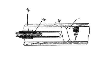
Figurs 11 shows diagrammatically the po~itio~ing
of the implant 1 in an organ pathway 18, for example a
blood vessel. A catheter 16 is pu~hed i~Yide the organ
pathway 1~ into the ~icinity of the site at which the
Lmplant 1 is to be positioned. The implant 1 is located,
in an extendad condition in the so-called primary shape,
in the inner lumen of the catheter and on the insertion
wire 14. Starting rom the di~tal end of the ca~heter,
which end is locatQd out~ide the bod~, the guide wire 14,
with the implant 1 loca~ed on it in extended form, i~
pushed forward into the organ pathway 18 to the site for
positioning. In ~tep ~, the secondary shape of the
implant i~ formed, from tha prLmary shape of the Lmplant
1 and as a re~ult of the spring ac~ion, in the organ
pathway 18 by withdrawing the guide wire 14 or by pu~hing
forward the stripping element 19. In step C, tha
secondary ~hape of the ~mplant 1 i~ developed further by
withdrawing the insertion catheter 16 and by further
withdrawal o~ the guide wixe 14, or by pu~hing forward
the stripping element 19, and in step D the position is
reached in which the guide wire 14 i8 contained in ~he
la~t section of the prima~y shape of the implant 1 and
the clamping sea~, due to the modified cross-section 7 of
the prLmary ~hape of the Lmpla~ 1, is still present o~
the guide wire 1~. In the emhodiment o~ the guide wire
represented in s~ep D, the wire pos esses an annular
grcove 15 in which the wall o~ the modified cross-section
of the primary shape, for exa~ple one or more spirals of
a wire 6 ha~ing a smaller cro~s-section, o~ at least a
cross-sectian which is reduced in one direction, engages.
In thi~ position there is, a~ter checking for the correct
positioning of the implant 1 in the organ pathway 18, a
final chance to withdraw the unrolled ~econdary shap~ of
the Lmplant 1 into the catheter 16 by pulling bac~ the
guide wire. The fact that the force req~ired to overcome
the clamping seat amounts to several time3 that required
to reextend ~he ~ormed secondary shape of the Lmplan~ 1
,,,, .. . ' . ~
. . ~ .
.
2 1 ~
W0 9~/144~8 - 16 - PCT/EP92toO2g4
and draw it back into the ca~heter 16 en~ure~ that it i5 --
possible to repo3ition the Lmplants according to the
invention in the case of an incorrect arrangement or an
unsuitable choice of shape. A stripping element lg is
arranged on the guide wire 14 in an axial direction
behind the prLmary shape of the Lmplant 1, the posterior
end of which element reache~ to the distal end of the
catheter. ~he stripping element can be a tube or el~e,
for reasons of elasticity, a spiral, who3e e~ternal
diameter coinrides wi~h the external diam~ter of the
primary shape of the Lmplant at its postPrior end. By
pushing forward the stripping element 19 in tha catheter
16 or.pulling back the guide wire 14 while keeping th~
~tripping elemen~ 19 stationary/ the clamping ~at o~ the
implan~ 1 on the guide wire 14 is released, and the end
of the guide wire is pulled out of the shape, or the
prLmary shape is stripped off from the end of the guide
wire. The Lmplant 1 then assumes the predetermined shape
in the organ pathway 18. Catheter 16 and st~ipping
element 19 are withdrawn from the organ pathway.
In the case of a tandem arrang~ment of implants,
two primary shapes, preferably implant~ having the
double-cone shape, are extended in a tandem arrangement
on a guide wire. The first implant i~ initially
2S positioned in the organ pathway, and then the second
Lmplant is unroll~d and positioned in the inner lumen of
this impla~t. In the case of double-coned implants, it i8
possible to arrange them so that at least a part of the
central section of the second implant remains in extended
form and thu~ exerts a traction effect on the ends of the
double-coned first implant.
The particular advantage of the configuration of
spiral Lmplants according to the invention i~ that the
implant can still be manipulated even in the implanted
state a3 long as it has still not been completely
uncoupled from the guide wire. The repositionability
which this pr~ides represents the crucial i~provement as
co~pared with con~entional technoloyy. Following
. , .
:, ' . ' ~:
. . . .
.
2 ~ 9
NO 92Jl4~08 - 17 - PCT~P92~00294
thrombo~ the region o the implant, a lasting
occlusion of ~he organ pathway, for example o~ blood
vessels, is provided. If resorbable implant material~
having a spring action are u~ed, no undesirable ~ide-
effects are ~o be expected, even over a long period oftime. The exact positioning can be monitored radio-
logically or by means of ultrasonic
, : . .. . . .
- . . . , , ~ . , : . ~