Note: Descriptions are shown in the official language in which they were submitted.
o l ~0 l 93 17: 34 ~39 2 ~5 / 3~ IINT. sRE~ETTI ~1003
2104139
~ACHINE ~OR ~IAKING A~l~ POSITIOI~INC; BAC7~ I~ADE; QF ~IVT-ME~J~T
PLASTIC ~5ATERIAL
The p~esent inve~ti.on relate~ to a machine fo~ maklns and
positio~ing ~a~s ~de of ho~.-rne~t plastic material, me~nt to
- be f;.lled with pr~ducts h.avi~g a sub~ar~tiallv pr:ismati~
~hape~
A very cornmon field of app~ication ~f the~e ma~hine~ is tl~e
packa~in~ of perishahle good,s or food E)roducts, such as
bakerY Product~ or brea~ loaves, ~hich ~st ~e irlserted ir
seal~d l~ags dire tly after haking ~o avoid lo~ heir
fragxance. ~aturally, the maclline accc,rdin~ ~ Lh~ inven~ior
~ can ~l~c be usQd fc,r nc)n-food products ~hicll rnust be
packaged in the same manner.
It i~ ~nc~wn that machines of ~.hi$ ]~ind mu~ a~ w -!'1l'
highest ~o~sible packaying ~peed il~ order to reduce
proce~ing times and to hand~e the c~apacitv c~f the up~trealn
arld down~3trealn $ys1~emS.
Corresporldingly, th~ Movement ~peed of the va~ious pa.rts, in
particular of the ~oll~eyc~r belt.s or of tl~e surface~ for thc
intermittent advancement of t~e ~ini.~hed b~c3s, must be kept
a~ h ~s po~ le to ,~llo~ a~l i.ncrease in capacity. The~e
cap3~-.ties and speed~ we~er, must he match~d by adeqllate
reliabilit.y and repetitivene,~s in order to ~void perlc~dic
stc~ppac~e~ ~nd a larger ~xe~ence o~ ~pe~visor~ per~onne~.
Currently commercially available machines allc~w capacit.ie~
of 40 to 6~ bags per min~te, with ~\eak 3peed~ c~f 100 to 120
m~ter~ per min~te. If the Flacka~Jing ~peed an~ rate are
0,~07 '93 17:3~ ~39 2 SG573~ I~. BRE~ETTI [~10(~
210~139
il~c~ea~ed, th~ relia~ility of tl~e ma~hir~e ~rops cf~n~i~ce~bly
and e~arl be ïnairltained only when the ma~hi~e is ne~ and with
~ccur~te adjustmerlts.
Italian pateht appl.icat~o~ no. VI9lA000085 de~cribe~ a
~ac~line ~or ma~ g bat~ made of hot-mel~ plasti~ mate~ia]
startin~ fro~ nd of transparent fillll made of l~o~-melt
material, and a mealls for the ~ntermitt.ellt advancement ~
t~le ~a~s toward a filling unit arrangeq ~ow~st~eanl ~ the
machine.
The filling station ~a~ ~ cl~np for ~ran~fer~1~Y one prc~du~t
at a time frvm a feeder belt tow~rd tlle filliny are~ of the
~a~hine. Before irl.ser-ting the product, each bag is inflated
bv meanC of a jet C~f ¢ompre~ed air which i~ emitt~d from a
~c1zzlé which is ~ligned with a ba~ s~curin~ means.
Altho~yh this Ina~hine allo~c: ~ cor~siderahle increa~
capacity, it has s~n~ acknowledged drawbacks which c~cc~ur
between the bay ~using and cutting step and the ~i~linf3
~tep.
- ~ fi~st draw~ack i~ due to th~ f~ct that in order ~o en~ure
t.~lat tlle productg to he inser~ecl in the oE~e~ hag~ ar~ always
ar~a~ged in the same pocitioll, ~7-1e tran~r cl~np includes
an anyular support with a lc~e~ surface which is incli~led .
- with res~ect to the hori~ontal. In ~his rnanner t during
in~lertic~n thc cl~mp entc:r~ tlle ~iag so that it i5 gli~htly
rotate~i with respect to the bag and Might int~.rfere with i~s
operl e~ge.
A fu~ther drawback of the ~iachil]e de~rihed in the a~c~ve
0 ~, 07 93 17: 35 ~39 2 ~5 ~ 3~ INT. BRE~ETTI 1~ 00.5
2109139
_ 3
mentioned pate~t consists of the fact that if the ~ag
advancemelJ~ ~ate is incrf~a~ed, tlle ~rip of the bag~ on tl-le
~upportiny ~urface in ~he regi~n directly up~tream of the
filling station dec~e~ses. Furthermore, the h~g can roll up
or ~ise lo~ally and cannot be 3tably retainecl prior to
inflation. I~ an~ ~ase, it is ne~e~sary to indica~e the
absence of an inflated bag in front of the filling ~tation
Another drawba~k co~si~ts of the Iac~t that t.he ~umes from
the ~usi~g of the edge~ of the bags Cr~ll be aspirated
together with the ~ur~ounding ai~ and be ~lvwn into the ha~
prior to sealing them.
~till another drawback i~ cons~itutecl ~y the imperfect or
e~ce~si~e rnelting of t.he fu~ed edge~ d~e to l~at dispersion
around the fusin~ blade~
~ ally, in order to va~y the ~idtl~ of the bag~ it ~
nece~a~y to perforrn complicated operation~ for adjusting
3rld sy~hroni.~~r~g ~ e advarlcernent ~peed of the macl-line with
the ~peed of tlle filli~y unit.
The aim of tl~le pres~ent i~ en-~iorl is ~o elimina~.e tlle
drawba.ck~ de~crihed above by providin~ a mac}-line for making
~nd l~c~ itionirlg ~ags ~ade of hot-Melting pla~tic material,
meant to ~e filled ~it.h product~ having a ~,uhstantially
pri~m~tic sh~pe, whi.cll includes ~ fra~e ~hich supports: a
~ea~5 for ~he feeding and i~terl[litterlt advance~ent b~ a b~nd
of hot-melt plastic matex ial ir~ a p~e~;e~ directif~r~; ~ rne~ 2
~or folding t~le ~d on itself alollg an intermediate lirle
with respe~ to the longitu~inzl ed~e~, ~o a~2 to form t.~.o
superimp~sed flap~ joined along the foldiclg lille, '2C~ that
0/~07 '93 1~:3~ 39 2 S6573~ I~rT. BRE~ETTI 1~!1006
~10~139
~- 4
the lower flap protrudes with respect to the u~per orle; a
me~ns for creating ~ ~ell~ws-like reces~ along the folding
line: a me~n~ ~or the simultaneou~ fusing an~ cuttin~ of the
~and folded alon~ a tra~sverse directi.on ill longit~dirlally
spaced positions, so aY to form a ~eries of ~djacent b~gs
which have orle side npen at the ~up~rimposed fl~ps; a
substantially horizontal mova~le conveyance surfa~e,
p~ovided with a negative-pressure means in a do~nward
region, for separating the bags and transferrinY them
.Reque~tial.~y toward a product filling station which is
provided with a clamp fnr grippin~ ol~e produ~t ~t a tlme
with a lower resting surface which i~ i.nclilled ~ith re~Pect
to the horizontal, the clamp being ~lov~ble, ~n a
reciprocatiny manne~, -tr~nsver~el~ with ~espe~t to t}~e ba~
advancemen~ di~ection; ~ means for injecting compressed air
ir~to each indi~idual ~ag through its o~en side to inflate it
prlor to filling; a secUring means for retaining each
irldividu~l bag along the edge of it~ lower flap ~urillg it~3
inflatlon by the in jec~tion means; w}lerein the securing means
is ~nounted ~o ~ to be able to os~illate on the frarne a~out
a substarltially hvrizontal trans~e~e a~is between a
~uh~tantially horizo~tal po~ition and an inclined pO~iti(.
~hich is su~stantially parallel to the restirlc~ su~f~e ~
the clamp of the fillin~ sta~i~r~ ~o a~ to perfectly align
the inflated ~a~ Wit}l ~e~pect ~o the pro~ucts, ~ in~
their insertioll ~itho~t i~lterference with the ed-~e of the
bac~.
In a furthe~ aspeCt, the securing me~ns incl~de~ a ba~e
member, which is pivoted to the frame with one en~, and a
pres~er which is ~uperimpo~ed on the member and can ~e moved
towa~d o~ a~ay from it i.n order to ~ecure the loose edge of
2 1 04 1 39
a bag.
Preferably, the presser has, in a substantially central
position, a main nozzle for injecting compressed air
into the secured bag.
It is possible to provide a secondary nozzle which is
arranged upstream of the securing means and is directed
toward the edge of the bag to be secured, in order to
keep it stably in contact with the conveyance surface at
the same level as the securing means in a horizontal
position.
In a further aspect of the invention, the fusing and
cutting means includes an electrically heated blade
which is interposed between, and elastically coupled to,
two lateral members for retaining the band, wherein the
retention members are hollow and are cooled by means of
a liquid coolant which circulates inside them so that
their edges which are in contact with the band remain at
a relatively low temperature during fusing.
According to a further broad aspect of the present
invention, there is provided a machine for making and
positioning bags made of hot-melting plastic material,
meant to be filled with products having a substantially
prismatic shape. The machine comprises a frame which
supports in succession; a means for the feeding and
intermittent advancement, in a preset direction, of a
band of hot-melt plastic material which is folded onto
itself along a longitudinal folding line, with
superimposed flaps and so that a lower flap protrudes
laterally with respect to an upper flap. A means for
creating a bellows-like recess along the folding line.
A means for the simultaneous fusing and cutting of the
_ 5a 21 041 39
band along a transverse direction in longitudinally
spaced positions, so as to form a series of adjacent
bags which have one side open on the opposite end with
respect to the folding line. A substantially horizontal
movable conveyance surface, provided with a negative-
pressure means in a downward region for separating the
bags and transferring them sequentially toward a product
filling unit which is provided with a clamp for gripping
one product at a time with a lower resting surface which
is inclined with respect to the horizontal. A means for
injecting compressed air into each individual bag
through its open side to inflate it prior to filling. A
means for securing each bag along the edge of the
protruding flap during inflation, wherein said securing
means is able to oscillate about a substantially
horizontal axis, which is at right angles to a product
advancement direction, between a substantially
horizontal position and an inclined position which is
substantially parallel to the lower resting surface of
said gripping clamp, so as to arrange the inflated bag
at the same angle as the product.
Brief DescriPtion of the drawinqs
For a better understanding of the invention, a preferred
embodiment of a bag-making machine according to the
invention is described hereinafter and is illustrated
only by way of non-limitative example in the
accompanying drawings, wherein:
Figure 1 is a general perspective view of a bag-making
machine according to the invention without a product
filling station;
07 9.3 17~3/ ~39 2 S~573~ INT. BRE~ETTI 121008
2104139
Fi.gure 2 is a partiallY ~ectiona~ side view of so~e details
of Figure 1
Figure 3 i~ a top ~iew of tlle terminal regi~ of the machine
acc~.o~diny to the i.nver~tion;
Figure 4 i~ a top elevation vi.ew of thf~ detail of Fif~ure 3;
Figurf~ 5 1~ a pe~rs~ef-tive vie~ of another detail of tl~e
mac~ine o~ Fir~ure 1:
Figu~e ~ is a ~ectional ~ie~ Of a detail of the ~usirlg a~d
o1uttil~9 device of th~ mac]l.irJe ac~o~di.rlg to tlle illverltiorl;
, ..
Fif~re 7 i~ a sche~na~ic side ~iew o~ ~ Eillin~ stativn whif~h
ca~ ~e used i~ as~sociatioll ~ith the machine acf~ordiny to t}:le
invention, ~n a laterally ~ranged position,
Pigure 8 i~ a ~chemati~ side vie~ of the filli~g ~tatic3n ~1.
Figure 7, illu~tratinf~ the relative p~s.ition of a det~.il cf
the machine a~cording to t~e invention.
With reference to the a~o~e $igures, ~ ~ay-m~king ïn~hine
acc~ordillg tc, t~le inventiorl, ~ener~lly designated by the~
reference n~meral 1, include~ a frame ~ made of pro~led
~emb~rs and metal pldte~ wh;iC]I support~ a series of ~e~i~e~
for m~ki~g b~gs S starting ~rom a ~and B nlade of ~l~t-melt
pl~stic m~terial,
~he hand B is ~onstituted ~y a filIn of hot melt Pla~tic
material whi~h h~s ~ thlckrless~ of a few microlls and is
preferably t~n~parent; the film is fvlded o~t.o it~elf
U7~0 ~ ' 93 1/: .38 '~.39 2 ~5, 3~ IN'T. BRE~ ETTI 1~ 009
2104139
beforeh~ld along a lo~itudinal direction, ~o that its t~o
flaps are superimpc,~d i~ ch a ~anner th~t olle flap is
~ider t~lan t~e otller, so t.h~t o~e o~ the ed~es ~ protrudes
with re~pe~t to the other.
The band ~ ~5 preliminarily ~nd on a roll or ree~ 3 whiCh
i~ rc)tat~ly supported ~y the frame and is stretche~ by
st~etching ~oller~ 4 and 5 210ng a ~ub3tantiallY horizo~tal
portic~n~ In thi~ pcJrtio~ there is a device 6 whi~h crPates a
bellcws-like recess at the fnld~ng line of the band B. The
device 6, of a per se known type, is ~on~tit.ut~d hy a pai.r~
of co~ial disk~ 7, which are ~utually spaced ~nc~ rotace
hetween the two flaps, and by an extern~] di~ 8 ~
compresse~ in~ard the folding line of ~he Eill~, making i.t
furm ~ r-e~ess.
~o~nstre~tn of the device 6, the hand ~ tretched by a
~et~hil~ roller ~ b~fore Pa~iny through ~ fusing 2n~
cutting urlit, generally d~si~nated by the re~erence numeral
10. A~ ~ho~n schema~ically in Figure 6, the ~rlit 10 i~
essenti~ coll~tituted ~y a transver~e blade 1.1 W}~
electrically heate~ at a ~onstant temper~ture whi~h i~
hi~her than the melting temperature of the band ~ and can
slide ~lor~ a ~ertical ~uiding m~an~, not shr~)wn in ~lle
d~awirlgs; a d~uble-a~t.ion actuator 12 act~ oll the ~l~de and
lo~e~ and lift.~ it at pre~et t.ime~.
The blade 1~ o-lpled, by ~neans ~f el~s~iC members, to tl~O
lateral retehtioh ~lem~ers 13 and 14 ~hich ~re bea~-shaP~d
toward their lo~e~ end so as to f~m ~o edges 15 and 16
whi~h ~e~,ain the band in pOsitioll ~gainst a flat lower
su~face prior to contact ~ith the fu~ing ~lade 11. 1'~he lower
0~07 '93 1~:39 ~39 2 S6~,3~ ;T. BRE~ETTI 1~
2101139
edge 1.7 o~ the blade ll i~ sh~rP, so as t.o a].so produce,
after f~sing, the cut alon~ a transver~ line. It i~ evldent
that each fu~ion and cut performed by the ~lade l~ form~ t~e
lateral ed~es of two ~djac~ent bag~ whi~h are clc~sed ~lonc~
three ~llsecuti~e c:i.de~ ~nd are operl at ~lle lateral edge
with the pr~rudil~ flap ~. ronvel~ielltly, the lateral
retention member~ 1.3 ~nd lY are made of metal s~eet ir order
t~ fo~m internal ~pace~ fvr the circ~lation of ~ater, c,r c~l.
any other refri~erati~g fluid. Particularly, water ~nay flow
in the spaces i~ide the mem~er~ 13, 14, ~y mean~ c-f
respecti.ve inlet pi~e~ lO' and out]et pipes lO", in turn
c.onnectecl to a~ e~te.rllal refrigerating as~emblY arran~ed i~-.
the frame of the machine and ~h-i~h is not illustrated in the
dr~wing~ for clarity. Down~tream of ~]le fusin~ and cuttiny
unit lO ther-e is a convey~r bel~ 1~ which is stretchQd ~y
~nd rc)llers lg ancl 2n ~o ~s to ~orm a hori~ont~l eonveyanc~
surf~e fc)r the ~dvan~ement of the fi~ished ba.g~. In order
tc~ increa~e the y~ip of the ba~s oll the conveYC)r helt l~,
the belt i~ pro~ided, oll its S~ e, w~ series of holes
~l through which air is drawn ~y mean~ of a lo~er cham~el:
22~ The cham~er ~2 is connected to ~n aspi~to~ ~4 by Inean~
of a pipe ~3~
The protrudin~ p F of the ha~ ret~ined ~y the conveyor
h~lt 18 rest~ on the side bf the frame laterallY to the
conveyor belt.
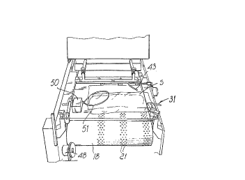
Proximate ~o the termlnal ~tretc~hin~ ~oller l9 there is a
device for se~ ing the prc~truding flap F of the haç~s during
~heir f illiny .
In p~rticula:r, the securing devi~e, gerlerally de~igrlat~d by
()l~O/ '93 17:40 ~39 2 8~573G I~T. BRE~ETTI 1~loll
210~139
tho ra:Earcnc::c l~um~ 5, lllclu~k;~ uppoJ.-ting m~mbcl 3Ç~
wllic~ ina~ti~e po~i~ion, has a~ upper surfac~e wllich i.
aligne~ with the Uppex portio~ of the conveyor belt la. ~
~r~ er memher 27 i~ a~o~iate~ with the ~llppc-rtin~ meml~er
2~ ahd can move along guides or po~ts 28 t 29 which are
rigidly coupled to the ~upp~rting ~em~e~ 26~ ~ fir~t
p~eumatic actuator 30 is coupled to t~e pres~e~ 27 and is
meant to mo~e the pre~er 27 cln~er and ~pace it so as t~
secure the p~o~r~din~ flap F af each bag~
A noz~le 3~ is in~erted in the p~e~er ~7 c~f the ~ecuri
device 25 and is connecte~ t~ an impeller to inflate the ba~
after the devic~ 25 has seçured the protruding flap F.
Accordin~ to the invention. the ~ecuring device 25 c~n
c)~ci~late. a~nut an a~i~ whi.cll is ~uh~tantiall~ ~oriz~llta
and ar. r~.ht angles to tlle ~ag advancement directic~n. In
particular, ~he ~upportil~Y ~emPer ~6 has all end whiC~]~
pivoted to a pivnt ~2 wl~ich i9 riyidly c~upled to the frame
2 alc~ng the ed~e ~f the con~eyf.~ helt 1~. There iS a ~ecc~
pr~eumatic actuator 33 for pe~indi~ally rotati~lg the
~pportlng memher 26, a]ld thus the elltir~ d~vice ~5, be tw~en
a sU~sta~tially h~izontal inact~e pO~itiOII alld a pocition
- wh:icl~ c.lirled by a prf-s~t allgle a.. Thl~ allgle must he
equal. to the o~e formed ~y t~e ~ow~ face of e~ch product P
t~ be pac~ka~ed when it 1.~ transferre~ ~y means ~f a fillir~y
unit, yenerally desiyna~ed ~y the reference n~mera]. 34.
As shown i.n Fiyu~es ~ ~nd ~. the filling unit 34 act~
tr~n~ver~ely between a l.i.n~ of Prf~duets P fo~med by a ~eeder
~elt 35 ~rranged in se~ie~ to an unlo~ding belt 36, and the
f onveyor ~elt 1~ o~ t~e machine 1. The belt 35 cau~e~ the
o~O, '93 17:~1 ~39 2 S~5,.3~ INT. BRE-ETTI l~!lol~
2104139
products to ~dvance in contact with abutment profiles 37
until they ~re unloaded ont~ the su~Sequent belt 36
The filling devi~e i~ ess~tially con~tituted by a clamp 38
~hich is formed by a supporting profiled mem~r with a lower
restin~ ~urface 39 which iS inclined hy an ~ngle a and h~s a
l~teral ~esting surface 40 Which is a~ ht ~gle~ ~o the
preceding one. The ~la~P also includes an upper profiled
memPer gl ~hich i~ meant to retain the produc~t P against th~
p~ofiled member 38. In n~der tc~ fill the ~ag. t~le clamp m~t
~ove tr~n~Yersely, by means of actuatc~rs 4~, so a~ to
tran~fer the product inside the bag. After this, the clamp
3~ opens slightl~, retaining the bag with the pr~duct inside
it, so as to t~ansfer it onto the unl~ading ~el~ 36.
A~c~rdlng to the in~ention, t~ere is a ~e~ond nozzle 43
whicll is ~ixed to the ed~e of the ~rame so as to ~irect a
iet of ~mpres~ed ai.r ~yainst the protrudln~ flap F directly
up~tream of the se~urinY mean~ 25, so a~ t~ ensure it~
op~imum insertion therein.
Furthermore, in order to increa~e ~e ~rip of the ~ags on
the co~lveyor belt la, the surfa~e of the ~elt is ¢overec~ ~y
a layer of ~lightly adhesi~e material, for exanlple silicone
~ubber.
In order to prevent the highly noxious ~u~ion fu}nes from
ente~ing t~le ~ags together with ~he in$1~tion ~i~, a hoc,d 4
is a~ranged on the ~u~in~ and cutting unit 10 and i~
~onnected ~y means of a tube 45 to an aspirato~ 46, with an
ac~ivated-carbon filter 47 interpo~ed.
0~,~07 ' ~3 17: ~1 ~39 ? 8~5, 36 I~T. BRE~ETTI ~ 13
Xl04139
11
Advantageously, in o~der to automati~ally vary the width of
the b~gs th~re i~ ~n encoder 4a which detects the pO~itiO
ahd speed of the c~onveyo~ ~elt and ~e~ds signals to a
programmable electronic controlle~ in~erted ln the cent~1
contrvl unit of the ~chi~e, By programming ~he controller,
the advancement speed ~nd the 3top ti~es are ~e~ so as to
vary the width o~ the bag ~hile ~eavin~ unchanged the
capacity a~d synchrc,nizatio~ ~ith re~pe~t tn the ~illing
unit.
In order to ~heck that the machil~e is operatin~ regularly,
at the securing mean~ ther~ ~s a detector 50 which
tran~duces the ~o~ition of a ring-~haped elastic contact
me~er 51. In ca~e of failure to infla~e, the detector ~end~
a signa]. ~o the controller, which automatically ~tops the
m~chine.
Pi.~ally, in order to allnw an exte~nal operator to ma~ually
s~op the machine, along tlle edge o~ the frame which i~
opposite to the filling area ~here is ~ ~afety switch,
formed by a steel wire 52 which has one end 53 ~ncho~ed to
f i~ed point of the frame and the other end 54 ~chore~ to a
remote swit~h 55 which clisconnect~ main power.
Through the above descri~ed fe~ture~, the p~çkaging m~chine
a~cordin~ to the invention reaches a capacity of up to 9Q
bag~ per minut~ at the maximum speed of the con~eyor be~t
without jamming and proving to ha~e a co~ erah~e
reliability. Moreover, the ~a~hine ensures optimal hygienic
condition~ requested for thia ~ype of packaging.
Although ~he m~c~ine according to the invention ha3 ~een
07, 07 '93 17:~2 ~39 2 8f35 7 3f; I.~T. BRE~ETTI 1~ flll
210~139
1~
de~ribed in a preferrcd cmbodimellt, it is evident. ~h~t it
i~ su~ceptible to nume~ou~ modification~ and variations
whi~h ~r~ within the .~ n~ ~he inve~tive concept
expreqsed ill the accom~anying 5~laim~.