Note: Claims are shown in the official language in which they were submitted.
CLAIMS
The embodiements of the invention in which an exclusive property or
privilege is claimed are defined as follows:
1. A method, for selectively controlling, subscriber access, to the
television channels, in a CATV system, that transmits, from its head end,
multiple channels' TV signals, that every subscriber has access to (the "BTV
channels") and multiple channels' TV signals, that every subscriber may not
have access to (the "EBTV channels"), wherein the BTV channels, and the EBTV
channels, are together, referred to as the "TOTAL CHANNELS", wherein the
TOTAL CHANNELS' TV signals, are transmitted from the head end, on a system
carrier wave, and wherein each subscriber, receives access, to some, or all,
of the TOTAL CHANNELS, through a receiver end, and wherein the CATV system,
from its head end, is also transmitting subscriber status signals ("SSS"s),
each of which, identifies which subscriber's receiver end, it is intended
for, and which of the TOTAL CHANNELS' TV signals, that subscriber's receiver
end, should jam the output of, to the subscriber, which method is
characterized, in that it is comprised of, the steps of:
(i) generating, from a head end, one at a time, six different
predetermined frequencies (each of which are hereinafter referred to in
general as "fx"), wherein each fx is stable in both amplitude and
frequency;
(ii) generating, from the head end, a synchronization signal ("sync.
sig.") that identifies which fx is being generated;
(iii) setting up a multiple of receiver ends, each of which:
(a) receives at one input, the TOTAL CHANNELS' TV signals, the SSS,
the fx, and the sync. sig.;
(b) divides the received signals, into: (1) TOTAL CHANNELS' TV
signals, SSS, and sync. sig., and (2) the fx;
(c) generates a local fixed frequency, which, each time it is
combined, with a different one of the six different fxs, will result
in a new frequency, that is suitable for jamming a different one of
the television signals, of the EBTV channels, and therefore, is a
jamming signal;
(d) mixes the local fixed frequency with the fx, thereby creating
a jamming signal;
(e) decoding the sync. sig.;
(f) decoding the SSS, to obtain the subscriber status information,
indicating whether that subscriber is entitled to receive any of
the TOTAL CHANNELS, and which, if any, of the EBTV channels, that
subscriber is not entitled to receive;
(g) transmitting the TOTAL CHANNELS, to the subscriber, if the
subscriber status information, indicates that subscriber is
entitled to receive some or all of the TOTAL CHANNELS; and
(h) combining the jamming signal, with the TOTAL CHANNELS' TV
signals, that are going to the subscriber, when the created
jamming signal, is for one of the channels, the subscriber status
information, indicates that subscriber is not entitled to receive.
2. A method, for selectively controlling, subscriber access, to the
television channels, in a CATV system, that transmits, from its head end,
multiple channels' TV signals, that every subscriber has access to (the "BTV
channels") and multiple channels' TV signals, that every subscriber may not
have access to (the "EBTV channels"), wherein the BTV channels, and the EBTV
channels, are together, referred to as the "TOTAL CHANNELS", wherein the
TOTAL CHANNELS' TV signals, are transmitted from the head end, on a system
carrier wave, and wherein each subscriber, receives access, to some, or all,
of the TOTAL CHANNELS, through a receiver end, and wherein the CATV system,
from its head end, is also transmitting subscriber status signals ("SSS"s),
each of which, identifies which subscriber's receiver end, it is intended
for, and which of the TOTAL CHANNELS' TV signals, that subscriber's receiver
end, should jam the output of, to the subscriber, which method is
characterized, in that it is comprised of, the steps of:
(i) generating, from the head end, one at a time, at predetermined
intervals, six different predetermined frequencies, each of which
frequencies, is stable in both amplitude and frequency, and each of
which frequencies, lasts for a predetermined duration, (each of which
frequencies is hereinafter referred to in general as "pfx");
(ii) generating from the head end, a synchronization signal, "sync.
sig.", that identifies which pfx is being generated;
(iii) at the head end, modulating the SSS onto the system carrier wave,
using frequency shift keying ("fsk");
(iv) at the head end, amplitude modulating, the sync. sig., onto the
system carrier wave;
(v) at the head end, combining all of the head end generated signals,
and the SSS, with the TOTAL CHANNELS' TV signals;
(vi) setting up a multiple of receiver ends, each of which:
(a) receives at one input, the TOTAL CHANNELS' TV signals, the SSS,
the pfx, and the sync. sig.;
(b) divides the received signals, into: (1) TOTAL CHANNELS' TV
signals, SSS, and sync. sig., and (2) the pfx;
(c) decodes the sync. sig.;
(d) decodes the SSS, to obtain the subscriber status information,
indicating whether that subscriber is entitled to receive any
of the TOTAL CHANNELS, and which, if any, of the EBTV channels,
that subscriber is not entitled to receive;
(e) transmitting the TOTAL CHANNELS' TV signals, to the subscriber,
if the subscriber status information, indicates that subscriber, is
entitled to receive at least some of the TOTAL CHANNELS;
(f) generating a local fixed frequency, the amplitude and frequency
of which are fixed and stable, which, each time it is combined, with
a different one of the six different pfxs, will result in a new
frequency, that is suitable for jamming a different one of the
television signals, of the EBTV channels, and therefore, is a jamming
signal;
(g) mixing the local fixed frequency, with the pfx, thereby creating
a jamming signal ("pfxj"); and
(h) combining pfxj, with the TOTAL CHANNELS' TV signal, that are
going to the subscriber, when pfxj is for one of the channels, that
the subscriber status information, indicates that subscriber is not
entitled to receive.
3. A method, for selectively controlling, subscriber access, to the
television channels, in a CATV system, that transmits, from its head end,
multiple channels' TV signals, that every subscriber has access to (the "BTV
channels") and multiple channels' TV signals, that every subscriber may not
have access to (the "EBTV channels"), wherein the BTV channels, and the EBTV
channels, are together, referred to as the "TOTAL CHANNELS", wherein the
TOTAL CHANNELS' TV signals, are transmitted from the head end, on a system
carrier wave, and wherein each subscriber, receives access, to some, or all,
of the TOTAL CHANNELS, through a receiver end, and wherein the CATV system,
from its head end, is also transmitting subscriber status signals, ("SSS"s),
each of which, identifies which subscriber's receiver end, it is intended
for, and which of the TOTAL CHANNELS' TV signals, that subscriber's receiver
end, should jam the output of, to the subscriber; as claimed in claims 1 or
2, wherein each of the six different pre-determined head end frequencies, are
each generated for a duration of 10 microseconds.
4. A method, for selectively controlling, subscriber access, to the
television channels, in a CATV system, that transmits, from its head end,
multiple channels' TV signals, that every subscriber has access to (the "BTV
channels") and multiple channels' TV signals, that every subscriber may not
have access to (the "EBTV channels"), wherein the BTV channels, and the EBTV
channels, are together, referred to as the "TOTAL CHANNELS", wherein the
TOTAL CHANNELS' TV signals, are transmitted from the head end, on a system
carrier wave, and wherein each subscriber, receives access, to some, or all,
of the TOTAL CHANNELS, through a receiver end, and wherein the CATV system,
from its head end, is also transmitting subscriber status signals ("SSS"s),
each of which, identifies which subscriber's receiver end, it is intended
for, and which of the TOTAL CHANNELS' TV signals, that subscriber's receiver
end, should jam the output of, to the subscriber; as claimed in claims 1 or
2, which, at each receiver end, is further comprised of:
(i) generating a second local fixed frequency, the amplitude and
frequency of which, are fixed and stable, which, each time it is
combined, with a different one, of the six different head end
generated pfxs, will result in a new frequency, that is suitable for
jamming, a different one of the television signals, of the EBTV
channels, and is a different frequency, than any of the pfxjs, that
would be created, when the first local fixed frequency, is combined,
with any, of the different ones, of the six different head end
generated pfxs, and therefore, is a different jamming signal,
hereinafter, referred to in general, as, "pfxj2";
(j) mixing the second local fixed frequency, with the pfx, thereby
creating, jamming signal, pfxj2; and
(k) combining pfxj2, with the TOTAL CHANNELS' TV signals, that are
going to the subscriber, when pfxj2, is for one of the channels, that
the subscriber status information, indicates that subscriber is not
entitled to receive.
5. A method, for selectively controlling, subscriber access, to the
television channels, in a CATV system, that transmits, from its head end,
multiple channels' TV signals, that every subscriber has access to (the "BTV
channels") and multiple channels' TV signals, that every subscriber may not
have access to (the "EBTV channels"), wherein the BTV channels, and the EBTV
channels, are together, referred to as the "TOTAL CHANNELS", wherein the
TOTAL CHANNELS' TV signals, are transmitted from the head end, on a system
carrier wave, and wherein each subscriber, receives access, to some, or all,
of the TOTAL CHANNELS, through a receiver end, and wherein the CATV system,
from its head end, is also transmitting subscriber status signals ("SSS"s),
each of which, identifies which subscriber's receiver end, it is intended
for, and which of the TOTAL CHANNELS' TV signals, that subscriber's receiver
end, should jam the output of, to the subscriber; as claimed in claims 1 or
2, which, at each receiver end, is further comprised of:
(i) generating a second local fixed frequency, the amplitude and
frequency of which, are fixed and stable, which, each time it is
combined, with a different one, of the six different head end
generated pfxs, will result in a new frequency, that is suitable for
jamming, a different one of the television signals, of the EBTV
channels, and is a different frequency, than any of the pfxjs, that
would be created, when the first local fixed frequency, is combined,
with any, of the different ones, of the six different head end
generated pfxs, and therefore, is a different jamming signal,
hereinafter, referred to in general, as, "pfxj2";
(j) mixing the second local fixed frequency, with the pfx, thereby
creating, jamming signal, pfxj2;
(k) combining pfxj2, with the TOTAL CHANNELS' TV signals, that are
going to the subscriber, when pfxj2, is for one of the channels, that
the subscriber status information, indicates that subscriber is not
entitled to receive; and
(l) wherein each of the six different predetermined head end
frequencies are each generated for a duration of 10 microseconds.
6. A method, for selectively controlling, subscriber access, to the
television channels, in a CATV system, that transmits, from its head end,
multiple channels' TV signals, that every subscriber has access to (the "BTV
channels") and multiple channels' TV signals, that every subscriber may not
have access to (the "EBTV channels"), wherein the BTV channels, and the EBTV
channels, are together, referred to as the "TOTAL CHANNELS", wherein the
TOTAL CHANNELS' TV signals, are transmitted from the head end, on a system
carrier wave, and wherein each subscriber, receives access, to some, or all,
of the TOTAL CHANNELS', through a receiver end, and wherein the CATV system,
from its head end, is also transmitting subscriber status signals ("SSS"s),
each of which, identifies which subscriber's receiver end, it is intended
for, and which of the TOTAL CHANNELS' TV signals, that subscribers receiver
end, should jam the output of, to the subscriber; as claimed in claims 1 or
2, which, at each receiver end, is further comprised of:
(i) generating a second local fixed frequency, the amplitude and
frequency of which, are fixed and stable, which, each time it is
combined, with a different one, of the six different head end
generated pfxs, will result in a new frequency, that is suitable for
jamming, a different one of the television signals, of the EBTV
channels, and is a different frequency, than any of the pfxjs, that
would be created, when the first local fixed frequency, is combined,
with any, of the different ones, of the six different head end
generated pfxs, and therefore, is a different jamming signal,
hereinafter, referred to in general, as, "pfxj2";
(j) mixing the second local fixed frequency, with the pfx, thereby
creating, jamming signal, pfxj2;
(k) combining pfxj2, with the TOTAL CHANNELS' TV signals, that are
going to the subscriber, when pfxj2, is for one of the channels, that
the subscriber status information, indicates that subscriber is not
entitled to receive;
(l) generating a third local fixed frequency, the amplitude and
frequency of which, are fixed and stable, which, each time it is
combined, with a different one, of the six different head end
generated pfxs, will result, in a new frequency, that is suitable for
jamming, a different one of the television signals, of the EBTV
channels, and is a different frequency, than any of the pfxjs, that
would be created, when the first local fixed frequency, or the second
local fixed frequency, is combined, with any, of the different ones,
of the six different head end generated pfxs, and therefore, is a
different jamming signal, hereinafter, referred to in general, as,
"pfxj3";
(m) mixing the third local fixed frequency, with the pfx, thereby
creating, jamming signal, pfxj3; and
(n) combining pfxj3, with the TOTAL CHANNELS' TV signals, that are
going to the subscriber, when pfxj3, is for one of the channels, that
the subscriber status information, indicates that subscriber, is not
entitled to receive.
7. A method, for selectively controlling, subscriber access, to the
television channels, in a CATV system, that transmits, from its head end,
multiple channels' TV signals, that every subscriber has access to (the "BTV
channels") and multiple channels' TV signals, that every subscriber may not
have access to (the "EBTV channels"), wherein the BTV channels, and the EBTV
channels, are together, referred to as the "TOTAL CHANNELS", wherein the
TOTAL CHANNELS' TV signals, are transmitted from the head end, on a system
carrier wave, and wherein each subscriber, receives access, to some, or all,
of the TOTAL CHANNELS, through a receiver end, and wherein the CATV system,
from its head end, is also transmitting subscriber status signals ("SSS"s),
each of which, identified which subscriber's receiver end, it is intended
for, and which of the TOTAL CHANNELS' TV signals, that subscriber's receiver
end, should jam the output of, to the subscriber; as claimed in claims 1 or
2, which, at each receiver end, is further comprised of:
(i) generating a second local fixed frequency, the amplitude and
frequency of which, are fixed and stable, which, each time it is
combined, with a different one, of the six different head end
generated pfxs, will result in a new frequency, that is suitable for
jamming, a different one of the television signals, of the EBTV
channels, and is a different frequency, than any of the pfxjs, that
would be created, when the first local fixed frequency, is combined,
with any, of the different ones, of the six different head end
generated pfxs, and therefore, is a different jamming signal,
hereinafter, referred to in general, as, "pfxj2";
(j) mixing the second local fixed frequency, with the pfx, thereby
creating, jamming signal, pfxj2;
(k) combining pfxj2, with the TOTAL CHANNELS' TV signals, that are
going to the subscriber, when pfxj2, is for one of the channels, that
the subscriber status information, indicates that subscriber is not
entitled to receive;
(l) generating a third local fixed frequency, the amplitude and
frequency of which, are fixed and stable, which, each time it is
combined, with a different one, of the six different head end
generated pfxs, will result, in a new frequency, that is suitable for
jamming, a different one of the television signals, of the EBTV
channels, and is a different frequency, than any of the pfxjs, that
would be created, when the first local fixed frequency, or the second
local fixed frequency, is combined, with any, of the different ones,
of the six different head end generated pfxs, and therefore, is a
different jamming signal, hereinafter, referred to in general, as,
"pfxj3";
(m) mixing the third local fixed frequency, with the pfx, thereby
creating, jamming signal, pfxj3;
(n) combining pfxj3, with the TOTAL CHANNELS' TV signals, that are
going to the subscriber, when pfxj3, is for one of the channels, that
the subscriber status information, indicates that subscriber, is not
entitled to receive; and
(o) wherein each of the six different predetermined head end
frequencies are each generated for a duration of 10 microseconds.
8. A method, for selectively controlling, subscriber access, to the
television channels, in a CATV system, that transmits, from its head end,
multiple channels' TV signals, that every subscriber has access to (the "BTV
channels") and multiple channels' TV signals, that every subscriber may not
have access to (the "EBTV channels"), wherein the BTV channels, and the EBTV
channels, are together, referred to as the "TOTAL CHANNELS", wherein the
TOTAL CHANNELS' TV signals, are transmitted from the head end, on a system
carrier wave, and wherein each subscriber, receives access, to some, or all,
of the TOTAL CHANNELS, a receiver end, and wherein the CATV system,
from its head end, is also transmitting subscriber status signals ("SSS"s),
each of which, identifies which subscriber's receiver end, it is intended
for, and which of the TOTAL CHANNELS' TV signals, that subscriber's receiver
end, should jam the output of, to the subscriber; as claimed in claims 1 or
2, which, at each receiver end, is further comprised of:
(i) generating a second local fixed frequency the amplitude and
frequency of which, are fixed and stable, which, each time it is
combined, with a different one, of the six different head end
generated pfxs, will result in a new frequency, that is suitable for
jamming, a different one of the television signals, of the EBTV
channels, and is a different frequency, than any of the pfxjs, that
would be created, when the first local fixed frequency, is combined,
with any, of the different ones, of the six different head end
generated pfxs, and therefore, is a different jamming signal,
hereinafter, referred to in general, as, "pfxj2";
(j) mixing the second local fixed frequency, with the pfx, thereby
creating, jamming signal, pfxj2;
(k) combining pfxj2, with the TOTAL CHANNELS' TV signals, that are
going to the subscriber, when pfxj2, is for one of the channels, that
the subscriber status information, indicates that subscriber is not
entitled to receive;
(l) generating a third local fixed frequency, the amplitude and
frequency of which, are fixed and stable, which, each time it is
combined, with a different one, of the six different head end
generated pfxs, will result, in a new frequency, that is suitable for
jamming, a different one of the television signals, of the EBTV
channels, and is a different frequency, than any of the pfxjs, that
would be created, when the first local fixed frequency, or the second
local fixed frequency, is combined, with any, of the different ones,
of the six different head end generated pfxs, and therefore, is a
different jamming signal, hereinafter, referred to in general, as,
"pfxj3";
(m) mixing the third local fixed frequency, with the pfx, thereby
creating, jamming signal, pfxj3;
(n) combining pfxj3, with the TOTAL CHANNELS' TV signals, that are
going to the subscriber, when pfxj3, is for one of the channels, that
the subscriber status information, indicates that subscriber, is not
entitled to receive;
(o) generating a forth local fixed frequency, the amplitude and
frequency of which are fixed and stable, which, each time it is
combined, with a different one, of the six different head end
generated pfxs, will result, in a new frequency, that is suitable for
jamming, a different one of the television signals, of the EBTV
channels, and is a different frequency, than any of the pfxjs, that
would be created, when the first local fixed frequency, or the second
local fixed frequency,, or the third local fixed frequency is
combined, with any, of the different ones, of the six different head
end generated pfxs, and therefore, is a different jamming signal,
hereinafter, referred to in general, as, "pfxj4";
(p) mixing the fourth local fixed frequency, with the pfx, thereby
creating jamming signal, pfxj4; and
(q) combining pfxj4 with the TOTAL CHANNELS' TV signals, that are
going to the subscriber, when the pfxj4, is for one of the channels,
that the subscriber status information, indicates that subscriber is
not entitled to receive.
9. A method, for selectively controlling, subscriber access, to the
television channels, in a CATV system, that transmits, from its head end,
multiple channels' TV signals, that every subscriber has access to (the "BTV
channels") and multiple channels' TV signals, that every subscriber may not
have access to (the "EBTV channels"), wherein the BTV channels, and the EBTV
channels, are together, referred to as the "TOTAL CHANNELS", wherein the
TOTAL CHANNELS' TV signals, are transmitted from the head end, on a system
carrier wave, and wherein each subscriber, receives access, to some, or all,
of the TOTAL CHANNELS, through a receiver end, and wherein the CATV system,
from its head end, is also transmitting subscriber status signals ("SSS"s),
each of which, identifies which subscriber's receiver end, it is intended
for, and which of the TOTAL CHANNELS' TV signals, that subscriber's receiver
end, should jam the output of, to the subscriber; as claimed in claims 1 or
2, which, at each receiver end, is further comprised of:
(l) generating a second local fixed frequency, the amplitude and
frequency of which, are fixed and stable, which, each time it is
conbined, with a different one, of the six different head end
generated pfxs, will result in a new frequency, that is suitable for
jamming, a different one of the television signals, of the EBTV
channels, and is a different frequency, than any of the pfxjs, that
would be created, when the first local fixed frequency, is combined,
with any, of the different ones, of the six different head end
generated pfxs, and therefore, is a different jamming signal,
hereinafter, referred to in general, as, "pfxj2";
(j) mixing the second local fixed frequency, with the pfx, thereby
creating, jamming signal, pfxj2;
(k) combining pfxj2, with the TOTAL CHANNELS' TV signals, that are
going to the subscriber, when pfxj2, is for one of the channels, that
the subscriber status information, indicate that subscriber is not
entitled to receive;
(l) generating a third local fixed frequency, the amplitude and
frequency of which, are fixed and stable, which, each time it is
combined, with a different one, of the six different head end
generated pfxs, will result, in a new frequency, that is suitable for
jamming, a different one of the television signals, of the EBTV
channels, and is a different frequency, than any of the pfxs, that
would be created, when the first local fixed frequency, or the second
local fixed frequency is combined, with any, of the different ones,
of the six different head end generated pfxs, and therefore, is a
different jamming signal, hereinafter, referred to in general, as,
"pfxj3";
(m) mixing the third local fixed frequency, with the pfx, thereby
creating, jamming signal, pfxj3;
(n) combining pfxj3, with the TOTAL CHANNELS' TV signals, that are
going to the subscriber, when pfxj3, is for one of the channels, that
the subscriber status information, indicates that subscriber, is not
entitled to receive;
(o) generating a forth local fixed frequency, the amplitude and
frequency of which are fixed and stable, which, each time it is
combined, with a different one, of the six different head end
generated pfxs, will result, in a new frequency, that is suitable for
jamming, a different one of the television signals, of the EBTV
channels, and is a different frequency, than any of the pfxjs, that
would be created, when the first local fixed frequency, or the second
local fixed frequency,, or the third local fixed frequency is
combined, with any, of the different ones, of the six different head
end generated pfxs, and therefore, is a different jamming signal,
hereinafter, referred to in general, as, "pfxj4";
(p) mixing the forth local fixed frequency, with the pfx, thereby
creating jamming signal, pfxj4;
(q) combining pfxj4 with the TOTAL CHANNELS' TV signals, that are
going to the subscriber, when the pfxj4, is for one of the channels
that the subscriber status information, indicates that subscriber is
not entitled to receive; and
(r) wherein each of the six different predetermined head end
frequency are each generated for a duration of 10 microseconds
10. An apparatus, for selectively controlling, subscriber access, to the
television channels, in a CATV system, that transmits, from its head end,
multiple channels' TV signals, that every subscriber has access to (the "BTV
channels") and multiple channels' TV signals, that every subscriber may not
have access to (the "EBTV channels"), wherein the BTV channels, and the EBTV
channels, are together, referred to, as the "TOTAL CHANNELS", wherein the
TOTAL CHANNELS' TV signals, are transmitted from the head end, on a system
carrier wave, and each subscriber, receives access, to some, or all,
of the TOTAL CHANNELS, through a receiver end, and wherein the CATV system,
from its head end, is also transmitting subscriber status signals ("SSS"s),
each of which, identifies which subscriber's receiver end, it is intended
for, and which of the TOTAL CHANNELS' TV signals, that subscriber's receiver
end, should jam the output of, to the subscriber; comprised of:
(i) a head-end; and
(ii) a multiple of receiver ends;
(iii) wherein the head end, is comprised of:
(a) multiple frequency generating means ("MFGM"), that generates,
one at a time, six different predetermined frequencies (each of which
are hereinafter referred to in general as "fx");
(b) a timing controller ("TC"), that controls the MFGM, and
additionally, generates a synchronization signal ("sync. sig.") that
identifies which fx is being generated; and
(iv) wherein the multiple receiver ends, are each comprised of:
(c) an input diplexer, that receives the TOTAL CHANNELS' TV signals,
the SSS, the fx, and the sync. sig., and which outputs, the TOTAL
CHANNELS' TV signals, the SSS, and the sync. sig., at a first output,
and which outputs, the fx, at a second output;
(d) a first directional coupler, that receives the signals, from the
first output, of the input diplexer;
(e) an isolation amplifier, that receives the signals, from the
first directional coupler;
(f) a data receiver, that also receives the signals, from the first
directional coupler, and extracts the SSS, and the sync. sig.;
(g) a first RF switch, that receives the signals, from the output,
of the isolation amplifier, and which either transmits, or prevents
the transmission, of the signals, to the subscriber;
(h) a local oscillator, that generates a predetermined local fixed
frequency, the amplitude and frequency of which, are fixed and
stable, which, each time it is combined, with a different one of the
six different fxs, will result in a new frequency, that is suitable
for jamming a different one of the television signals, of the EBTV
channels, and therefore, is a jamming signal, hereinafter called,
"fxj";
(i) a mixer, that receives the predetermined local fixed frequency,
and receives the fx, outputted at the second output of the input
diplexer, and mixes them, thereby creating jamming signal, fxj;
(j) an amplifier, suitable for raising the level of fxj, in order to
achieve effective jamming;
(k) a second RF switch, that receives the fxj, and when closed,
transmits it to the amplifier, and when open, prevents the
transmission, of the fxj, to the amplifier;
(l) a second directional coupler, that couples, the output of the
amplifier, with the output of the isolation amplifier, at an
intermediate point, between the isolation amplifier, and the first RF
switch;
(m) a microprocessor, that receives the extracted SSS from the data
receiver, decodes the SSS, to determine whether or not the subscriber
is authorized to receive at least some of the TOTAL CHANNELS, and
which, if any, of the EBTV channels, the subscriber is authorized to
receive, and if the subscriber is not authorized to receive any of
\
the TOTAL CHANNELS, prevents the first RF switch from closing, and if
the subscriber is authorized to receive at least some of the TOTAL
CHANNELS, prevents the first RF switch from opening; and
(n) a synchronization controller, that receives the sync. sig., from
the data receiver, and receives the extracted SSS, from the
microprocessor, and decodes the sync. sig., and decodes the SSS, and
causes the second RF switch, to close, whenever the fxj, is jamming
an EBTV channel, that the subscriber is not authorized to receive,
thereby transmitting the fxj, to the amplifier, and to the
subscriber, for TV channels, which the subscriber is not authorized
to receive.
11. An apparatus for selectively controlling, subscriber access, to the
television channels, in a CATV system, that transmits, from its head end,
multiple channels' TV signals, that every subscriber has access to (the "BTV
channels") and multiple channels' TV signals, that every subscriber may not
have access to (the "EBTV channels"), wherein the BTV channels, and the EBTV
channels, are together, referred to, as the "TOTAL CHANNELS", wherein the
TOTAL CHANNELS' TV signals, are transmitted from the head end, on a system
carrier wave, and wherein each subscriber, receives access, to some, or all,
of the TOTAL CHANNELS, through a receiver end, and wherein the CATV system,
from its head end, is also transmitting subscriber status signals ("SSS"s),
each of which, identifies which subscriber's receiver end, it is intended
for, and which of the TOTAL CHANNELS' TV signals, that subscriber's receiver
end, should jam the output of, to the subscriber; as claimed in claim 10,
wherein each receiver end, is also comprised of:
(o) a second local oscillator, that generates a second predetermined
local fixed frequency the amplitude and frequency of which are fixed
and stable, which, each time it is combined, with a different one, of
the six different head end generated fxs, will result in a new
frequency, that is suitable for jamming a different one of the
television signals, of the EBTV channels, and is a different
frequency, than any of the fxjs, that would be created, when the
first local fixed frequency, is combined, with any, of the different
ones, of the six different head end generated fxs, and therefore, is
a different jamming signal, hereinafter, referred to in general, as,
"fxj2";
(p) a second mixer;
(q) a splitter, that receives the fx, from the second output, of the
input diplexer, and sends it to each of the first and second mixers;
(r) wherein the second mixer, receives the fx, from the splitter,
and receives the second predetermined local fixed frequency and
mixes them, thereby creating, a second jamming signal, fxj2;
(s) a third RF switch, that receives the fxj2, from the second
mixer;
(t) a second amplifier, suitable for raising the level of fxj2, in
order to achieve effective jamming;
(u) wherein the third RF switch, either transmits, or prevents the
transmission, of fxj2, to the second amplifier;
(v) a combiner, that receives the fxj, when it is outputted from the
first amplifier, and receives the fxj2, when it is outputted from the
second amplifier, and sends them to the second directional coupler;
(w) a filter, intermediate, between the first RF switch, and the
subscriber output, that filters out the EBTV channels;
(x) a fourth RF switch, intermediate, between the second directional
coupler, and the subscriber output, that can output, to the
subscriber the TOTAL CHANNELS' TV signals;
(y) a microprocessor, that receives the extracted SSS, from the data
receiver, decodes the SSS, to determine, whether or not the
subscriber is authorized to receive at least some of the TOTAL
CHANNELS, and which, if any, of the EBTV channels, the subscriber is
authorized to receive, and if the subscriber is not authorized to
receive any of the TOTAL CHANNELS, prevents the first RF switch, and
the fourth RF switch, from closing, and if the subscriber is only
authorized to receive the BTV channels, closes the first RF switch,
and causes the fourth RF switch to remain open, and if the subscriber
is authorized to receive the BTV channels and at least some of the
EBTV channels, causes the fourth RF switch to remain closed; and
(z) a synchronization controller, that receives the sync. sig., from
the data receiver, and the extracted SSS, from the microprocessor,
and decodes the sync. sig., and decodes the SSS, and causes the
second RF switch, to close, whenever the fxj, is jamming an EBTV
channel, that the subscriber is not authorized to receive, and causes
the third RF switch, to close, whenever the fxj2, is jamming an EBTV
channel, that the subscriber is not authorized to receive, thereby
transmitting, the fxj, and the fxj2, to their respective amplifiers,
and to the subscriber, for EBTV channels, which the subscriber is not
authorized to receive.
12. An apparatus, for selectively controlling, subscriber access, to the
television channels, in a CATV system, that transmits, from its head end,
multiple channels' TV signals, that every subscriber has access to the "BTV
channels") and multiple channels' TV signals, that every subscriber may not
have access to (the "EBTV channels"), wherein the BTV channels, and the EBTV
channels are together, referred to as the "TOTAL CHANNELS', wherein the
TOTAL CHANNELS' TV signals, are transmitted from the head end, on a system
carrier wave, and wherein each subscriber, receives access, to some, or all,
of the TOTAL CHANNELS, through a receiver end, and wherein the CATV system,
from its head end, is also transmitting subscriber status signals ("SSS" s),
each of which, identifies which subscriber's receiver end, it is intended
for, and which of the TOTAL CHANNELS' TV signals, that subscriber's receiver
end, should jam the output of, to the subscriber; as claimed in claim 10,
wherein each receiver end, is also comprised of:
(o) a second local oscillator, that generates a second predetermined
local fixed frequency, the amplitude and frequency of which are fixed
and stable, which, each time it is combined, with a different one, of
the six different head end generated fxs, will result in a new
frequency, that is suitable for jamming, a different one of the
television signals, of the EBTV channels, and is a different
frequency, than any of the fxjs, that would be created, when the
first local fixed frequently, is combined, with any, of the different
ones, of the six different head end generated fxs, and therefore, is
a different jamming signal, hereinafter, referred to in general, as,
"fxj2";
(p) a second mixer;
(q) a splitter, that receives the fx, from the second output, of the
input diplexer, and sends it to each of the first and second mixers;
(r) wherein the second mixer, receives the fx, from the splitter,
and receives the second predetermined local fixed frequency, and
mixes them, thereby creating, a second jamming signal, fxj2;
(s) a third RF switch, that receives the fxj2, from the second
mixer;
(t) a second amplifier, suitable for raising the level of fxj2, in
order to achieve effective jamming;
(u) wherein the third RF switch, either transmits, or prevents the
transmission, of fxj2, to the second amplifier;
(v) a third local oscillator, that generates a third
predetermined local fixed frequency, the amplitude and frequency of
which, are fixed and stable, which, each time it is combined, with a
different one, of the six different head end generated fxs, will
result in a new frequency, that is suitable for jamming, a different
one of the television signals, of the EBTV channels, and is a
different frequency, than any of the fxjs, that would be created,
when the first local fixed frequency, or the second local fixed
frequency, is combined, with any, of the different ones, of the six
different head end generated fxs, and therefore, is a different
jamming signal, hereinafter, referred to in general, as, "fxj3";
(w) a third mixer;
(x) wherein the splitter, that receives the fx, from the second
output, of the input diplexer, and sends it to each of the first, and
second mixers, also sends it to the third mixer;
(y) wherein the third mixer, receives the fx, from the splitter, and
receives the third predetermined local fixed frequency, and mixes
them, thereby creating a third jamming signal, fxj3;
(z) a fourth KF switch, that receives the fxj3, from the third
mixer;
(aa) a third amplifier suitable, for raising the level of fxj3, in
order to achieve effective jamming;
(bb) wherein the fourth RF switch, either transmits, or prevents the
transmission, of fxj3, to the third amplifier;
(cc) a combiner, that receives the fxj, when it is outputted from the
first amplifier, and receives the fxj2, when it is outputted from the
second amplifier, and receives the fxj3, when it is outputted from
the third amplifier, and sends them to the second directional
coupler;
(dd) a filter, intermediate, between the first RF switch, and the
subscriber output, that filters out the EBTV channels;
(ee) a fifth RF switch, intermediate, between the second directional
coupler, and the subscriber output, that can output, to the
subscriber the TOTAL CHANNELS' TV signals;
(ff) a microprocessor, that receives the extracted SSS, from the data
receiver, decodes the SSS, to determine, whether or not the
subscriber is authorized to receive, at least some of the TOTAL
CHANNELS, and which, if any, of the EBTV channels, the subscriber is
authorized to receive, and if the subscriber is not authorized to
receive any of the TOTAL CHANNELS, prevents the first RF switch, and
the fifth RF switch, from closing, and if the subscriber is only
authorized to receive the BTV channels, closes the first RF switch,
and causes the fifth RF switch to remain open, and if the subscriber
is authorized to receive the BTV channels, and at least some of the
EBTV channels, causes the fifth RF switch, to remain closed; and
(gg) a synchronization controller, that receives the sync. sig., from
the data receiver, and the extracted SSS, from the microprocessor,
and decodes the sync. sig., and decodes the SSS, and causes the
second RF switch, to close, whenever the fxj, is jamming an EBTV
channel, that the subscriber is not authorized to receive, and causes
the third RF switch, to close, whenever the fxj2, is jamming an EBTV
channel, that the subscriber is not authorized to receive, and causes
the fourth RF switch, to close, whenever the fxj3, is jamming an EBTV
channel, that the subscriber is not authorized to receive, thereby
transmitting, the fxj, the fxj2, and the fxj3, to their respective
amplifiers, and to the subscriber, for EBTV channels, which the
subscriber is not authorized to receive.
13. An apparatus, for selectively controlling, subscriber access, to the
television channels, in a CATV system, that transmits, from its head end,
multiple channels' TV signals, that every subscriber has access to (the BTV
channels") and multiple channels' TV signals, that every subscriber may not
have access to (the "EBTV channels"), wherein the BTV channels, and the EBTV
channels, are together, referred to, as the "TOTAL CHANNELS", wherein the
TOTAL CHANNELS' TV signals, are transmitted from the head end, on a system
carrier wave, and wherein each subscriber, receives access, to some, or all,
of the TOTAL CHANNELS, through a receiver end, and wherein the CATV system,
from its head end, is also transmitting subscriber status signals ("SSS"s),
each of which, identifies which subscriber's receiver end, it is intended
for, and which of the TOTAL CHANNELS' TV signals, that subscriber's receiver
end, should jam the output of, to the subscriber; as claimed in claim 10,
wherein each receiver end, is also comprised of:
(o) a second local oscillator, that generates a second predetermined
local fixed frequency, the amplitude and frequency of which are fixed
and stable, which, each time it is combined, with a different one, of
the six different head end generated fxs, will result in a new
frequency, that is suitable for jamming, a different one of the
television signals, of the EBTV channels, and is a different
frequency, than any of the fxjs, that would be created, when the
first local fixed frequency, is combined, with any, of the different
ones, of the six different head end generated fxs, and therefore, is
a different jamming signal, hereinafter, referred to in general, as,
"fxj2";
(p) a second mixer;
(q) a splitter, that receives the fx, from the second output, of the
input diplexer, and sends it to each of the first and second mixers;
(r) wherein the second mixer, receives the fx, from the splitter,
and receives the second predetermined local fixed frequency and
mixes them, thereby creating, a second jamming signal, fxj2;
(s) a third RF switch, that receives the fxj2, from the second
mixer;
(t) a second amplifier, suitable for raising the level of fxj2, in
order to achieve effective jamming;
(u) wherein the third RF switch, either transmits, or prevents the
transmission, of fxj2, to the second amplifier;
(v) a third local oscillator, that generates that generates a third
predetermined local fixed frequency, the amplitude and frequency of
which, are fixed and stable, which, each time it is combined with a
different one, of the six different head end generated fxs, will
result in a new frequency, that is suitable for jamming, a different
one of the television signals, of the EBTV channels, and is a
different frequency, than any of the fxjs, that would be created,
when the first local fixed frequently, or the second local fixed
frequency, is combined, with any, of the different ones, of the six
different head end generated fxs, and therefore, is a different
jamming signal, hereinafter, referred to in general, as, "fxj3";
(w) a third mixer;
(x) wherein the splitter, that receives the fx, from the second
output, of the input diplexer, and sends it to each of the first, and
second mixers, also sends it to the third mixer;
(y) wherein the third mixer, receives the fx, from the splitter, and
receives the third predetermined local fixed frequency, and mixes
them, thereby creating a third jamming signal, fxj3;
(z) a fourth RF switch, that receives the fxj3, from the third
mixer;
(aa) a third amplifier suitable, for raising the level of fxj3, in
order to achieve effective jamming;
(bb) wherein the fourth RF switch, either transmits, or prevents the
transmission, of fxj3, to the third amplifier;
(cc) a fourth local oscillator that generates a fourth predetermined
local fixed frequency, the amplitude and frequency of which are fixed
and stable, which, each time it is combined, with a different one, of
the six different head end generated fxs, will result in a new
frequency, that is suitable for jamming, a different one of the
television signals, of the EBTV channels, and is a different
frequency than any of the fxjs, that would be created, when the
first local fixed frequency, or the second local fixed frequency, or
the third local fixed frequency, is combined, with any, of the
different ones, of the six different head end generated fxs, and
therefore, is a different jamming signal, hereinafter, referred to in
general, as, "fxj4";
(dd) a fourth mixer;
(ee) wherein the splitter, also sends the fx to the fourth mixer;
(ff) wherein the fourth mixer, receives the fx from the splitter, and
receives the fourth predetermined local fixed frequency, and mixes
them, thereby creating a fourth jamming signal, fxj4;
(gg) a fifth RF switch, that receives the fxj4 from the fourth mixer;
(hh) a fourth amplifier, suitable for raising the level of fxj4, in
order to achieve effective jamming;
(ii) wherein the fifth RF switch, either transmits, or prevents the
transmission of fxj4, to the fourth amplifier;
(jj) a combiner, that receives the fxj, when it is outputted from the
first amplifier, and receives the fxj2, when it is outputted from the
second amplifier, and receives the fxj3, when it is outputted from
the third amplifier, and receives the fxj4, when it is outputted from
the fourth amplifier, and sends them to the second directional
coupler;
(kk) a filter, intermediate, between the first RF switch, and the
subscriber output, that filters out the EBTV channels;
(ll) a sixth RF switch, intermediate, between the second directional
coupler, and the subscriber output, which can output to the
subscriber, the TOTAL CHANNELS' TV signals;
(mm) a microprocessor, that receives the extracted SSS, from the data
receiver, decodes the SSS, to determine, whether or not, the
subscriber is authorized to receive, at least some of the TOTAL
CHANNELS, and which, if any, of the EBTV channels, the subscriber is
authorized to receive, and if the subscriber is not authorized to
receive any of the TOTAL CHANNELS, prevents the first RF switch, and
the slxth RF switch, from closing, and if the subscriber is only
authorized to receive the BTV channels, closes the first RF switch,
and causes the sixth RF switch, to remain open, and if the
subscriber, is authorized to receive the BTV channels, and at least
some of the EBTV channels, causes the sixth RF switch, to remain
closed; and
(nn) a synchronization controller, that receives the sync.sig., from
the data receiver, and the extracted SSS, from the microprocessor,
and decodes the sync. sig., and decodes the SSS, and causes the
second RF switch, to close, whenever the fxj, is jamming an EBTV
channel, that the subscriber is not authorized to receive, and causes
the third RF switch to close, whenever the fxj2, is jamming an EBTV
channel, that the subscriber is not authorized to receive, and causes
the fourth RF switch to close, whenever the fxj3, is jamming an EBTV
channel, that the subscriber is not authorized to receive, and causes
the fifth RF switch to close, whenever the fxj4, is jamming an EBTV
channel, that the subscriber is not authorized to receive, thereby
transmitting, the fxj, the fxj2, the fxj3, and the fxj4, to their
respective amplifiers, and to the subscriber, for EBTV channels,
which the subscriber is not authorized to receive.
14. An apparatus, for selectively controlling, subscriber access, to the
television channels, in a CATV system, that transmits, from its head end,
multiple channels' TV signals, that every subscriber has access to (the "BTV
channels") and multiple channels' TV signals, that every subscriber may not
have access to (the "EBTV channels"), wherein the BTV channels, and the EBTV
channels, are together, referred to, as the "TOTAL CHANNELS", wherein the
TOTAL CHANNELS' TV signals, are transmitted from the head end, on a system
carrier wave, and wherein each subscriber, receives access, to some, or all,
of the TOTAL CHANNELS, through a receiver end, and wherein the CATV system,
from its head end, is also transmitting subscriber status signals ("SSS"s),
each of which, identifies which subscriber's receiver end, it is intended
for, and which of the TOTAL CHANNELS' TV signals, that subscriber's receiver
end, should jam the output of, to the subscriber; as claimed in claim 10:
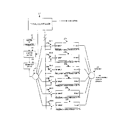
wherein the multiple frequency generating means, of the head end, is
comprised up of:
(o) a master IF oscillator, that generates a signal of a
predetermined frequency, that is stable in both amplitude and
frequency;
(p) a master RF switch ("MRF"), that receives the signal from the
master IF oscillator;
(q) a bandpass filter, that receives the signal from the MRF, and
which further reduces the harmonics that caused by the switching of
the master IF oscillator;
(r) six frequency agile modulators;
(s) six RF switches, each of which is coupled, at one end, to a
unique one, of the six frequency agile modulators;
(t) a splitter, that divides the outputted signal, from the bandpass
filter, six ways, one to each of the six RF switches;
(u) a combiner, that merges the outputs, of the six frequency agile
modulators, into one main output, which is to be combined, with the
TOTAL CHANNELS' TV signals;
(v) a timing controller ("TC"), that puts out a sync. sig., and
closes, and opens, the MRF, for a predetermined duration, at fixed
intervals, and sequentially closes, and opens, and continues to
sequentially close, and open, each of the six RF switches, beginning
with the first one, for approximately the same predetermined
duration, at the same fixed intervals, as it closes, and opens, the
MRF, to enable the six frequency agile modulators, to sequentially
receive, the signal bursts, through the bandpass filter; and
(w) wherein the six frequency agile modulators, output six different
predetermined frequencies, each of which frequencies, is stable, in
both amplitude and frequency, and each of which, lasts for a
predetermined duration, and wherein the sync. sig., identifies which
of the six different predetermined frequencies, is being generated.
15. An apparatus, for selectively controlling, subscriber access, to the
television channels, in a CATV system, that transmits, from its head end,
multiple channels' TV signals, that every subscriber has access to (the "BTV
channels") and multiple channels' TV signals, that every subscriber may not
have access to (the "EBTV channels wherein the BTV channels, and the EBTV
channels, are together, referred to, as the "TOTAL CHANNELS", wherein the
TOTAL CHANNELS' TV signals, are transmitted from the head end, on a system
carrier wave, and wherein each subscriber, receives access, to some, or all,
of the TOTAL CHANNELS, through a receiver end, and wherein the CATV system,
from its head end, is also transmitting subscriber status signals ("SSS"s),
each of which, identifies which subscriber's receiver end, it is intended
for, and which of the TOTAL CHANNELS' TV signals, that subscriber's receiver
end, should jam the output of, to the subscriber; as claimed in claim 10:
wherein the multiple frequency generating means, of the head end, is
comprised up of:
(o) a master IF oscillator, that generates a signal of a
predetermined frequently, that is stable in both amplitude and
frequency;
(p) a matter RF switch ("MRF"), that receives the signal from the
master IF oscillator;
(q) a bandpass filter, that receives the signal from the MRF, and
which further reduces the harmonics that caused by the switching of
the master IF oscillator;
(r) six frequency agile modulators;
(s) six RF switches, each of which is coupled, at one end, to a
unique one, of the six frequency agile modulators;
(t) a splitter, that divides the outputted signal, from the bandpass
filter, six ways, one to each of the six RF switches ;
(u) a combiner, that merges the outputs, of the six frequency agile
modulators, into one main output, which is to be combined, with the
TOTAL CHANNELS' TV signals;
(v) a timing controller ("TC"), that puts out a sync. sig., and
closes and opens, the MRF, for a predetermined duration, at fixed
intervals, and sequentially closes, and opens, and continues to
sequentially close, and open, each of the six switches, beginning
with the first one, for approximately the same predetermined
duration, at the same fixed intervals, as it closes, and opens, the
MRF, to enable the six frequency agile modulators, to sequentially
receive, the signal bursts, through. the bandpass filter;
(w) wherein the six frequency agile modulators, output six different
predetermined frequencies, each of which frequencies, is stable, in
both amplitude and frequency, and each of which, lasts for a
predetermined duration, and wherein the sync. sig., identifies which
of the six different predetermined frequencies, is being generated;
(x) and wherein the sync. sig. is amplitude modulated onto the
system carrier wave;
(y) and wherein the SSS, is frequency shift key ("fsk"), modulated,
onto the system carrier wave; and
(z) wherein the data receivers, of the receiver ends, extract the
sync. sig., and the SSS, form the system carrier wave, by
demodulating them.
16. An apparatus, for selectively controlling, subscriber access, to the
television channels, in a CATV system, that transmits, from its head end,
multiple channels' TV signals, that every subscriber has access to (the "BTV
channels") and multiple channels' TV signals, that every subscriber may not
have access to (the "EBTV channels"), wherein the BTV channel, and the EBTV
channels, are together, referred to, as the "TOTAL CHANNELS", wherein the
TOTAL CHANNELS' TV signals, are transmitted from the head end, on a system
carrier wave, and wherein each subscriber, receives access, to some, or all,
of the TOTAL CHANNELS, through a receiver end, and wherein the CATV system,
from its head end, is also transmitting subscriber status signals ("SSS"s),
each of which, identifies which subscriber's receiver end, it is intended
for, and which of the TOTAL CHANNELS' TV signals, that subscriber's receiver
end, should jam the output of, to the subscriber; as claimed in claim 10:
wherein the multiple frequency generating means, of the head end, is
comprised up of:
(o) a master IF oscillator, that generates a signal of a
predetermined frequency, that is stable in both amplitude and
frequency;
(p) a master RF switch ("MRF"), that receives the signal from the
master IF oscillator;
(q) a bandpass filter, that receives the signal from the MRF, and
which further reduces the harmonics that caused by the switching of
the master IF oscillator;
(r) six frequency agile modulators;
(s) six RF switches, each of which is coupled, at one end, to a
unique one, of the six frequency agile modulators;
(t) a splitter, that divides the outputted signal, from the bandpass
filter, six ways, one to each of the six RF switches;
(u) a combiner, that merges the outputs, of the six frequency agile
modulators, into one main output, which is to be combined, with the
TOTAL CHANNELS' TV signal;
(v) a timing controller ("TC"), that puts out a sync. sig., and
closes, and opens, the MRF, for a predetermined duration, at fixed
intervals, and sequentially closes, and opens, and continues to
sequentially close, and open, each of the six RF switches, beginning
with the first one, for approximately the same predetermined
duration, at the same fixed intervals, as it closes and opens, the
MRF, to enable the six frequency agile modulators, to sequentially
receive, the signal bursts, through the bandpass filter;
(w) wherein the six frequency agile modulators output six different
predetermined frequencies, each of which frequencies, is stable, in
both amplitude and frequency, and each of which, lasts for a
predetermined duration, and wherein the sync. sig., identifies which
of the six different predetermined frequencies, is being generated;
(x) and wherein the sync. sig. is amplitude modulated onto the
system carrier wave;
(y) and wherein the SSS, is frequency shift key ("fsk"), modulated,
onto the system carrier wave;
(z) wherein the data receivers, of the receiver ends, extract the
sync. sig., and the SSS, form the system carrier wave, by
demodulating them; and
wherein each receiver end, is also comprised of:
(aa) a second local oscillator, that generates a second predetermined
local fixed frequency, the amplitude and frequency of which are fixed
and stable, which, each time it is combined, with a different one, of
the six different head end generated fxs, will result in a new
frequency, that is suitable for jamming, a different one of the
television signals, of the EBTV channels, and is a different
frequency, than any of the fxjs, that would be created, when the
first local fixed frequency, is combined and with any, of the different
ones, of the six different head end generated fxs, and therefore, is
a different jamming signal, hereinafter, referred to in general, as,
"fxj2";
(bb) a second mixer;
(cc) a splitter, that receives the fx, from the second output, of the
input diplexer, and sends it to each of the first and second mixers;
(dd) wherein the second mixer, receives the fx, from the splitter,
and receives the second predetermined local fixed frequency, and
mixes them, thereby creating, a second jamming signal, fxj2;
(ee) a third RF switch, that receives the fxj2, from the second
mixer;
(ff) a second amplifier, suitable for raising the level of fxj2, in
order to achieve effective jamming;
(gg) wherein the third RF switch, either transmits, or prevents the
transmission, of fxj2, to the second amplifier;
(hh) a combiner, that receives the fxj, when it is outputted from the
first amplifier, and receives the fxj2, when it is outputted from the
second amplifier, and sends them to the second directional coupler;
(ii) a filter, intermediate, between the first RF switch, and the
subscriber output, that filters out the EBTV channels;
(jj) a fourth RF switch, intermediate, between the second directional
coupler, and the subscriber output, that can output, to the
subscriber the TOTAL CHANNELS' TV signals;
(kk) a microprocessor, that receives the extracted SBB, from the data
receiver, decodes the SSS, to determine whether or not the
subscriber it authorized to receive at least some of the TOTAL
CHANNELS, and which, if any, of the EBTV channels, the subscriber is
authorized to receive, and if the subscriber is not authorized to
receive any of the TOTAL CHANNELS, prevents the first RF switch, and
the fourth RF switch, from closing, and if the subscriber is only
authorized to receive the BTV channels, closes the first RF switch,
and causes the fourth RF switch to remain open, and if the subscriber
is authorized to receive the BTV channels and at least some of the
EBTV channels, causes the fourth RF switch to remain closed; and
(ll) a synchronization controller, that receives the sync. sig., from
the data receiver, and the extracted SSS, from the microprocessor,
and decodes the sync. sig., and decodes the SSS, and cause the
second RF switch, to close, whenever the fix is jamming an EBTV
channel, that the subscriber is not authorized to receive, and causes
the third RF switch, to close, whenever the fxj2, is jamming an EBTV
channel, that the subscriber is not authorized to receive, thereby
transmitting, the fxj and the fxj2, to their respective amplifiers,
and to the subscriber, for EBTV channels, which the subscriber is not
authorized to receive.
17. An apparatus, for selectively controlling, subscriber access, to the
television channels, in a CATV system, that transmits, from its head end,
multiple channels' TV signals, that every subscriber has access to (the "BTV
channels") and multiple channels' TV signals, that every subscriber may not
have access to (the "EBTV channels"), wherein the ETV channels, and the EBTV
channels, are together, referred to, as the "TOTAL CHANNELS" wherein the
TOTAL CHANNELS' TV signals, are transmitted from the head end, on a system
carrier wave, and wherein each subscriber, receives access, to some, or all,
of the TOTAL CHANNELS, through a receiver end, and wherein the CATV system,
from its head end, is also transmitting subscriber status signals ("SSS"s),
each of which, identifies which subscribers receiver end, it is intended
for, and which of the TOTAL CHANNELS' TV signals, that subscriber's receiver
end, should jam the output of, to the subscriber; comprised of:
(i) a head-end; and
(ii) a multiple of receiver ends;
(iii) wherein the head end, is comprised of:
(a) multiple frequency generating means ("MFGM"), that generates,
one at a time, six different predetermined frequencies (each of which
are hereinafter referred to in general as "fx");
(b) a timing controller ("TC"), that controls the MFGM, and
additionally, generates a synchronization signal ("sync. sig.") that
identifies which fx is being generated; and
(iv) wherein the multiple receiver ends, are each comprised of:
(c) an input diplexer, that receives the TOTAL CHANNELS' TV signals,
the SSS, the fx, and the sync. sig., and which outputs, the TOTAL
CHANNELS' TV signals, the SSS, and the sync. sig., at a first output,
and which outputs, the fx, at a second output;
(d) a first directional coupler, that receives the signals, from the
first output, of the input diplexer;
(e) a first splitter that receives the signals from the output of
the first directional coupler;
(f) a first isolation amplifier, that receives the signal from the
first splitter;
(g) a second isolation amplifier, that receives the signal from the
first splitter;
(h) a first RF switch that receives the signals from the output of
the first isolation amplifier and which either transmits of prevents
the transmission of the signals to the first subscriber;
(i) a second RF switch that receives the signals from the output of
the second isolation amplifier and which either transmits or prevents
the transmission of the signals to the second subscriber;
(j) a data receiver, that also receives the signals, from the first
directional coupler, and extracts the SSS, and the sync. sig.;
(k) a local oscillator, that generates a predetermined local fixed
frequency, the amplitude and frequency of which, are fixed and
stable which, each time it is combined, with a different one of the
six different fxs, will result in a new frequency, that is suitable
for jamming a different one of the television signals, of the EBTV
channels and therefore, is a jamming signal, hereinafter called,
"fxj";
(l) a mixer, that receives the predetermined local fixed frequency,
and receives the fx, outputted at the second output of the input
diplexer, and mixes them, thereby creating jamming signal, fxj;
(m) an amplifier, suitable for raising the level of fxj, in order to
achieve effective jamming;
(n) a second splitter, that receive the raised fxj, from the
amplifier;
(o) a third RF switch, that receives the fxj, from the second
splitter, and which either transmits, or prevents the transmission,
of the fxj, to the first subscriber;
(p) a fourth RF switch, that receives the fxj, from the second
splitter, and which either transmits, or prevents the transmission,
of the fxj, to the second subscriber;
(q) a second directional coupler, that couples the output, of the
third RF switch, with the output, of the first isolation amplifier,
at an intermediate point, between the first isolation amplifier, and
the first RP switch;
(r) a third directional coupler, that couples the output, of the
fourth RF switch, with the output, of the second isolatlon amplifier,
at an intermediate point, between the second isolation amplifier, and
the fourth RF switch;
(s) a microprocessor, that receives the extracted SSS, from the data
receiver, decodes the SSS, to determine, whether or not a subscriber
is authorized to receive at least some of the TOTAL CHANNELS, and
which, if any, of the EBTV channels that subscriber is authorized to
receive, and if that subscriber is not authorized to receive any of
the TOTAL CHANNELS, prevents the appropriate one, of the first and
second RF switches, as the case may be, from closing, and if a
subscriber is authorized to receive at least some of the TOTAL
CHANNELS, prevents the appropriate one, of the first and second RF
switches, from opening; and
(t) a synchronization controller, that receives the sync. sig., from
the data receiver, and the excluded SSS, from the microprocessor,
and decodes the sync. sig., and decodes the SSS, and causes the third
RF switch to close, whenever the fxj, is jamming an EBTV channel,
that the first subscriber is not authorized to receive, and causes
the fourth RF switch, to close, whenever the fxj, is jamming an EBTV
channel, that the second subscriber is not authorized to receive,
thereby transmitting the fxj, to the amplifier, and to the
appropriate subscriber, for EBTV channels, which that subscriber, is
not authorized to receive.
18. An apparatus, for selectively controlling, subscriber access, to the
television channels, in a CATV system, that transmits, from its head end,
multiple channels' TV signals, that every subscriber has access to (the "BTV
channels") and multiple channels' TV signals, that every subscriber may not
have access to (the "EBTV channels"), wherein the BTV channels, and the EBTV
channels, are together, referred to, as the "TOTAL CHANNELS", wherein the
TOTAL CHANNELS' TV signals, are transmitted from the head end, on a system
carrier wave, and wherein each subscriber, receives access, to some, or all,
of the TOTAL CHANNELS, through a receiver end, and wherein the CATV system,
from its head end, is also transmitting subscriber status signals ("SSS"s),
each of which, identifies which subscriber's receiver end, it is intended
for, and which of the TOTAL CHANNELS' TV signals, that subscribers receiver
end, should jam the output of, to the subscriber; as claimed in claim 17,
wherein the multiple frequency generating means, of the head end, is
comprised of:
(u) a master IF oscillator, that generates a signal of a
predetermined frequency, that is stable in both amplitude and
frequency;
(v) a master RF switch ("MRF"), that receives the signal from the
master IF oscillator;
(w) a bandpass filter, that receives the signal from the MRF, and
which further reduces the harmonics that caused by the switching of
the master if oscillator;
(x) six frequency agile modulators;
(y) six RF switches, each of which is coupled, at one end, to a
unique one, of the six frequency agile modulators;
(z) a splitter, that divides the outputted signal, from the bandpass
filter, six ways, one to each of the six RF switches;
(aa) a combiner, that merges the outputs, of the six frequency agile
modulators, into one main output, which is to be combined, with the
TOTAL CHANNELS' TV signals;
(bb) a timing controller ("TC"), that puts out a sync. sig., and
closes, and opens, the MRF, for a predetermined duration, at fixed
intervals, and sequentially closes, and opens, and continues to
sequentially close, and open, each of the six RF switches, beginning
with the first one, for approximately the same predetermined
duration, at the same fixed intervals, as it closes, and opens, the
MRF, to enable the six frequency agile modulators, to sequentially
receive, the signal bursts, through the bandpass filter; and
(cc) wherein the six frequency agile modulators, output six different
predetermined frequencies, each of which frequencies, is stable, in
both amplitude and frequency, and each of which, lasts for a
predetermined duration, and wherein the sync. sig., identifies which
of the six different predetermined frequencies, is being generated.
19. An apparatus, for selectively controlling, subscriber access, to the
television channel in a CATV system, that transmits from its head end,
multiple channels' TV signals that every subscriber has access to (the "BTV
channels") and multiple channels' TV signals, that every subscriber may not
have access to (the "EBTV channels"), wherein the BTV channels, and the EBTV
channels, are together, referred to, as the "TOTAL CHANNELS", wherein the
TOTAL CHANNELS' TV signals, are transmitted from the head end, on a system
carrier wave, and wherein each subscriber, receives access, to some, or all,
of the TOTAL CHANNELS, through a receiver end, and wherein the CATV system,
from its head end, is also transmitting subscriber status signals ("SSS"s),
each of which, identifies which subscriber's receiver end, it is intended
for, and which of the TOTAL CHANNELS' TV signals, that subscriber's receiver
end, should jam the output of, to the subscriber; comprised of:
(i) a head-end; and
(ii) a multiple of receiver ends;
(iii) wherein the head end, is comprised of:
(a) multiple frequency generating means ("MFGM"), that generates,
one at a time, six different predetermined frequencies (each of which
are hereinafter referred to in general as "fx");
(b) a timing controller ("TC"), that controls the MFGM, and
additionally, generates a synchronization signal ("sync. sig.") that
identifies which fx is being generated; and
(iv) wherein the multiple receiver ends, are each comprised of:
(c) an input diplexer, that receives the TOTAL CHANNELS' TV signals,
the SSS, the fx, and the sync. sig., and which outputs the TOTAL
CHANNELS' TV signals, the SSS, and the sync. sig., at a first output,
and which outputs the fx, at a second output;
(d) a first directional coupler, that receives the signals, from the
first output, of the input diplexer;
(e) an isolation amplifier, that receives the signals, from the
first directional coupler;
(f) a data receiver, that also receives the signals, from the first
directional coupler, and extracts the SSS, and the sync. sig.;
(g) a first RF switch, that receives the signals, from the output, of
the isolation amplifier, and which either transmits, or prevents the
transmission of the signals to the subscriber;
(h) a local oscillator, that generates a predetermined local fixed
frequency, the amplitude and frequency of which, are fixed and
stable, which, each time it is combined, with a different one of the
six different fxs, will result in a new frequency, that is suitable
for jamming a different one of the television signals, of the EBTV
channels, and therefore, is a jamming signal, hereinafter referred
to, as, "fxj";
(i) a mixer, that receives the predetermined local fixed frequency,
and receives the fx, outputted at the second output of the input
diplexer, and mixes them, thereby creating jamming signal, fxj;
(j) a second diplexer, that receives the fxj from the mixer, and
separates it, into its sum signal, "fxj+", and its difference signal,
"fxj-";
(k) a second RF switch, that receives fxj+, from the second
diplexer;
(l) a third RF switch, that receives fxj-, from the second diplexer;
(m) an amplifier, suitable for raising the level of fxj+, in order
to achieve effective jamming;
(n) an amplifier, suitable for raising the level of fxj-, in order
to achieve effective jamming;
(o) a combiner, that combines the signals, from the two amplifiers;
(p) a second directional coupler, that couples the output, of the
two amplifiers, with the output, of the isolation amplifier, at an
intermediate point, between the isolation amplifier, and the first RF
switch;
(q) a microprocessor, that receives the extracted SSS, from the data
receiver, decodes the SSS, to determine, whether or not the
subscriber, is authorized to receive, at least some of the TOTAL
CHANNELS, and which, if any, of the EBTV channels, the subscriber is
authorized to receive, and if the subscriber is not authorized to
receive any of the TOTAL CHANNELS, prevents the first RF switch from
closing, and if the subscriber is authorized to at least receive the
BTV channels, prevents the first RF switch from opening; and
(r) a synchronization controller, that receives the sync. sig., from
the data receiver, and the extracted SSS, from the microprocessor,
and decodes the sync. sig., and decodes the SSS, and causes the
second RF switch, to close, whenever the fxj+, is jamming an EBTV
channel, that the subscriber is not authorized to receive, and causes
the third RF switch, to close, whenever the fxj-, is jamming an EBTV
channel, that the subscriber is not authorized to receive, thereby
transmitting the fxj+, and the fxj-, to their respective amplifiers,
and to the subscriber, for EBTV channels, which the subscriber, is
not authorized to receive.
20. An apparatus, for selectively controlling, subscriber access, to the
television channels, in a CATV system, that transmits, from its head end,
multiple channels' TV signals, that every subscriber has access to (the "BTV
channels") and multiple channels' TV signals, that every subscriber may not
have access to (the "EBTV channels"), wherein the BTV channels, and the EBTV
channels, are together, referred to, as the "TOTAL CHANNELS", wherein the
TOTAL CHANNELS' TV signals, are transmitted from the head end, on a system
carrier wave, and wherein each subscriber, receives access, to some, or all,
of the TOTAL CHANNELS, through a receiver end, and wherein the CATV system,
from its head end, is also transmitting subscriber status signals ("SSS"s),
each of which, identifies which subscriber's receiver end, it is intended
for, and which of the TOTAL CHANNELS' TV signals, that subscriber's receiver
end, should jam the output of, to the subscriber; as claimed in claim 19,
wherein the multiple frequency generating means, of the head end, is
comprised of:
(s) a master IF oscillator, that generates a signal of a
predetermined frequency, that is stable in both amplitude and
frequency;
(t) a master RF switch ("MRF"), that receives the signal from the
master IF oscillator;
(u) a bandpass filter, that receives the signal from the MRF, and
which further reduces the harmonics that caused by the switching of
the master IF oscillator;
(v) six frequency agile modulators;
(w) six RF switches, each of which is coupled, at one end, to a
unique one, of the six frequency agile modulators;
(x) a splitter, that divides the outputted signal, from the bandpass
filter, six ways, one to each of the six RF switches;
(y) a combiner, that merges the outputs, of the six frequency agile
modulators, into one main output, which is to be combined, with the
TOTAL CHANNELS' TV signals;
(z) a timing controller ("TC"), that puts out a sync. sig., and
closes, and opens, the MRF, for a predetermined duration, at fixed
intervals, and sequentially closes, and opens, and continues to
sequentially close, and open, each of the six RF switches, beginning
with the first one, for approximately the same predetermined
duration, at the same fixed intervals, as it closes, and opens, the
MRF, to enable the six frequency agile modulators, to sequentially
receive, the signal bursts, through the bandpass filter; and
(aa) wherein the six frequency agile modulators, output six different
predetermined frequencies, each of which frequencies, is stable, in
both amplitude and frequency, and each of which, lasts for a
predetermined duration, and wherein the sync. sig., identifies which
of the six different predetermined frequencies, is being generated.