Note: Descriptions are shown in the official language in which they were submitted.
21~ 4 ~ J Attorney Docket No. 20~920
(9558)
SURGICAI~ Cl,A~P APPARATUS
5 BACKGROUND OF THE ~VENTION
1. Field of the In~ention
The subject invention relates to surgical apparatus for performing
laparoscopic and endoscopic surgical procedures, and more particularly to a surgical
clamp apparatus and method for applying the clamp during a surgical procedure
10 2. Description of Related Art
During surgical operations in which it is necessary to open the intestinal
wall to expose the interior lumen, a surgeon must place a clamp across the intesdne above
and below the point of entry Prior art surgical clamping devices for clamping tubular
15 vessels such as the intestines are well Icnown For example, U.S. Patent No 4,976,721
to Blasnik et al describes a manually operable clamp having parallel jaw members biased
in a closed position by a spring which is maintained within a housing portion of the
clamp. Other surgical clamps having spring biased parallel jaw members include those
20 described in U S Patent No 3,509,882 to Blake and U.S. Patent No. 4,931,058 to
~ooper.
A bowel clamp and a detachable applicator for applying the clamp are
disclosed in U.S. Patent No. 3,916,908 ~o Leveen ln particular, Leveen shows a
disposable bowel clamp which comprises two rod members each having a hook structure
at one end thereof and an apenure at the opposed end which the hook structure engages
Each of the rods are held within respective jaws of the applicator in such a manner so that
the jaws of the applicator, once closed, fasten the rod members securdy together, thereby
forming a clamp. Once the clamp has been placed on the vessel, the applicator is30 detached from the clamp and removed for use elsewhere. The apparatus shown in Leveen
is limited in application however, to conventional surgical procedures in which the
surgeon has direct access to the abdominal cavily
-2-
2~ ~q~
Ther~ is a perceived need in the art for adaptation of a detachable bowel
clamp, suc~ as that disclosed in Leveen, for endoscopic or laparoscopic procedures. In
these procedures a small incision or puncture is made in the patient's body to provide
5 access for a tube or cannula device which allows insertion of surgical apparatus. Thus, to
avoid requiring separate incisions for each instrument having a clamp, there is a perceived
need in the art for a clamp detachably mounted to the instrument which could be inserted
through a cannula, clamped onto a vessel and which remains there while the instrument
10 which delivered the clamp to the site is withdrawn through the cannula and used to deliver
another clamp to the operative site.
Such an endoscopic surgical instrument having a detachable clamp for the
bowel would, like other bowel clamps, have atraumatic jaws which are angled and include
15 tabs for preventing the bowel from slipping out. The handle and the jaws of the
instrument would also be spring loaded, and as is desirable with endoscopic instruments,
the instrument would be rotatable and capable of angling for easier application of the
clamp.
While there is a perceived need in the art for the above-described
20 instrument, due to the complexity of such instrument, to date no one has developed an
endoscopic instrument which enables the application and withdrawal of detachable bowel
clamps. The complexity of such an instrument, and hence the diMcul~y of its
development, is due to the requirements that it be operable at a region remote from the
25 clamp to actuate the jaws of the clamp~ detach lhe clamp, re-attach the clamp at the
surgical site, as well as allow for rotation and angling of the instrument.
SU~ARY OF THE INV~NTION
While the subject invention is described herein with respect to a device for
applying a bowel clamp, the applicability of the instrument should nol be limited thereto
for it is envisioned that the surgical apparatus of the subject invention would be useful in
2la;~c~
many endoscopic or laparoscopic procedures wherein it is necessary to apply a surgical
clamp to a tubular vessel.
A surgical apparatus is therefore disclosed, in accordance with a preferred
S embodiment of the subject invention, for applying a surgical clamp during an endoscopic
procedure and subsequently retrieving the clamp upon completion of the procedure. The
apparatus comprises a handle portion, an endoscopic portion which extends longitudinally
from the handle portion, and a surgical clamp which is detachably mounted adjacent a
10 distal end of the endoscopic portion of the instrument. The clamp includes a pair of
opposed cooperating jaw members which are movable between a normally closed position
and an open position. The apparatus further comprises structural means, associated with
the endoscopic portion of the instrument, for detachably engaging the clamp which
comprises a pair of opposed engaging arms mounted on a resilient base structure and
adapted to be cammed from an outstre~ched disengaged position to an engaged position
wherein the engaging arms interlock with the surgical clamp. The instrument is also
provided wi~h means for moving the opposed cooperating jaw members of the surgical
clamp between the normally closed position and the open position.
Preferably, a distal end portion of the endoscopic portion of the apparalus l'
is adapted for articulation relative to the longitudinal axis of the endoscopic portion so as ~,
to increase the range of operability of the instrument. Accordingly, the apparatus includes
means which ue associated with ~he handle portion thereof for effectuating the articulation
25 of the distal end portion of the endoscopic portion. The appuatus also includes seal
means which are provided in the endoscopic portion thereof for inhibiting the egress of
insumation gas therethrough.
The subject invention is fur~her directed to a method for applying a surgical
30 clamp during an endoscopic or lapuoscopic procedure which includes the steps of
providing an appuatus including a handle portion and un endoscopic portion extending
from the handle portion having opposed engaging arms at a distal end thereof fordetachably mounting a surgical clamp, engaging the surgical clamp adjacent the distal end
2-~Q~3~
portion of the endoscopic portion of ~he apparatus, extending the endoscopic portion and
the clamp through a cannula device and into the abdominal cavity of the patient, moving
the opposed jaw members from an initially closed position to an open position, positioning
the clamp in a desired position relative to the tubular vessel to be clamped, moving the
opposed jaw member of t'ne clamp from the open position to a closed position, and
disengaging the opposed engaging arms from the surgical clamp so as to detach the clamp
from the distal end portion of the apparatus.
Further features of the subject invention will become more readily apparent
from the following detailed description of the invention taken in conjunction with the
accompanying drawings.
~RTEF I)ESCRlPl'ION OF THE DRAWI~GS
Preferred embodiments of the subject invention will be describeà
hereinbelow with reference to the drawings, wherein:
Fig. l is a perspective view of an endoscopic surgical apparatus in
accordance with ? preferred embodiment of the subject invention;
Fig. 2 is an enlarged side elevational view in cross-seclion taken along line
2-2 of ~'ig. l;
Fig. 3 is an exploded perspective view of the distal end portion of the
endoscopic surgical appara~us of Fig.l;
Fig. 4 is an enlarged side elevational view of the surgical apparatus of Fig.
l;
Fig. 5 is a side elevational view in cross-section of the apparatus of Fig. l
with the surgical clamp in a normally closed position;
Fig. 6 is a top plan view in cross-section taken along line 6-6 of Fig. 5
with the engaging structure in a disengaged position;
Fig. 7 is a side elevational view in cross-section of the apparatus of Fig. l
with the pivoting handle in a partially closed position;
2 ~ O ~ v ~ 3
Fig. 8 is a top plan view in cross-section taken along line 8-8 of Fig. 7
with the engaging structure in an engaged position;
Fig. 9 is a side elevational view in cross-section of the apparatus of Fig. 1,
with the distal end portion thereof in an articulated position;
Fig. 10 is a side elevational view in cross-section of the apparatus of Fig.
1, with the distal end portion thereof in an articulated position wherein the clamp is in an
open position;
Fig. 11 is a side elevational view of the upper jaw member of the surgical
clamp of the subject invention;
Fig. 12 is a bottom plan view of the upper jaw member of Fig. 11;
Fig. 13 is a rear elevational view of the upper jaw member of Fig. 11;
Fig. 14 is a side elevational view, partially broken away, of the lower jaw
member of the surgical clamp of the subject invention;
Fig. 15 is a top plan view, in partial cross-section, of the lower jaw
member of Fig. 14;
Fig. 16 is a rear elevational view of the lower jaw member of Fig. 14;
Fig. 17 is a top plan view of ~hé barrel member shown in Fig. 3;
Fig. 18 is a side elevational view of the link member shown in Fig. 3;
Fig. 19 is a side elevational view of the surgical clamp engaging structure
shown in Fig. 3; and
Fig. 20 is a top plan view of the surgical clamp engaging structure of Fig.
19.
~I~El~ DE:SCRT~ION OF TH~: PREFl~ ED EMBODI~:NTS
In the drawings and in the description which follows, the term "proximal"
refers to the end which is closest to the operator while the term "distal" will refer to the
end which is furthest from the operator.
2 ~3 .i 1,
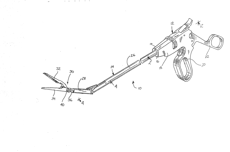
The surgical apparatus of the subject invention is illustrated in Fig. 1 and is
designated generally by reference numeral 10. Surgical apparatus 10 comprises a handle
portion 12 including opposed hemi-portions 14 and 16 which are mounted to one another
5 to define a body 18 and a fixed handle 20. A pivoting handle 22 is movably connected to
body 18 adjacent fixed handle 20. Surgical apparatus 10 further comprises an endoscopic
portion 24 which extends from the body 18 of handle portion 12 and which includes an
elongated proximal portion 26 and an articulating portion 28 which is movably mounted at
10 a distal end of proximal portion 26. A surgical clamp 30 having opposed cooperating jaw
members 32 and 34 is detachably mounted to the articulating portion 28 of endoscopic
portion 24 by a barrel 36 which extends outwardly from surgical clamp 30. Engaging
structure 40 is associated with the articulating portion 28 for detachably mounting surgical
1 5 clamp 30 to apparatus 10.
Referring to Fig. 2, handle portion 12 further comprises a trigger
mechanism which includes a trigger 50 pivotably mounted to body portion 18 by a pin 52
and movable within a chamber 54 which is defined in body portion 18. Trigger 50 is
provided with an internal spring member 56 which biases trigger 50 into an engaging
20 position in the direction of indicator arrow "A". Once biased into the engaging position,
a ratchet link 58, which is pivotably connected to trigger 50 by a pin 60 and which is
mounted within ~rigger chamber 54 by a pin 62, engages a rack member 64 mounted for
reciprocating longi~udinal movement in body portion 18 and operatively associated with
25 the endoscopic portion 24 of surgical apparatus 10. Specifically, a ratchet catch 66 which
depends from ratchet link 58 is engagable between a plurality of teeth defined in rack
member 64 for selectively controlling the longitudinal movement of rack member 64. In
addition, a travel stop detent 68 extends rearwardly from trigger 50 for stopping trigger
30 50 against a shelf 70 which is formed in chamber 54 as biasing spring 56 returns trigger
50 to its engaging position.
Pivoting handle 22 is mounted to the body 18 of handle portion 12 by a
pivot pin 72. A biasing spring 74 and a thrust member 76 are mounted within a slot 78
.
2 t O '1~ 1 ~
in pivoting handle 22 and extend into a groove 80 formed in fixed handle 20.
Compression of pivoting handle 22 in the direction of indicator arrow "B" will compress
biasing spring 74 against thrust member 76 so as to store energy to return the pivoting
S handle 22 when it is released. A universal joint member 82 is associated with the upper
portion of pivoting handle 22 and is operatively conrJected to a mechanism for controlling
the cooperative movement of the jaws 32 and 34 of surgical clamp 30, and in addition,
for controlling the engaging structure 40 which is associated with the articulating portion
28 of endoscopic portion 24 for detachably engaging surgical clarnp 30. The control
mechanism includes an elongated rod member 84 having a head 86 formed at the
proximal end thereof which is engaged in a universal joint 82. The distal end of rod
member 84 is engaged in a coupling member 88 which is disposed in endoscopic portion
24 and more particularly, within an inner tube 90 of endoscopic portion 24. A proximal
end of an elongated control cable 92 is engaged in coupling member 88 and a distal end
of control cable 92 extends operatively through endoscopic portion 24 to engaging
structure 40.
Handle portion 12 further comprises a mechanism for moving the
20 articulating portion 28 of endoscopic portion 24 relative to the longitudinal axis of
proximal portion 26. The articu]ating mechanism includes a latch member 96 which is
pivotably mounted in the body 18 of handle portion 12 by a pivot pin 98. Latch member
96 is formed with an arcuate portion 100 having a plurality of gear teeth 102 defined
thereon. Gear teeth 102 mesh operatively with an elongated rack member 104 having
corresponding gear teeth 105 and disposed movably within a longitudinal chamber 106
formed in handle portion 12. A draw arm 110 is mounted to the under-surface of rack
member 104 and includes a hook structure 112 formed at a distal end thereof. Hook
structure 112 is adapted and configured to engage a flange-like structure 114 formed on ''~!'
the proximal end of an internal tube 116 which is operatively mounted for coaxial
translation within an outer tube 118 of endoscopic portion 24. Flange-like structure 114
is dimensioned to translate within an annular chamber 120 defined in the body 18 of
2t ~3 1',
handle portion 12. Manipulation of latch member 96 will~cause gear teeth 102 on the
annular portion lO0 of latch member 96 to operatively intermesh with teeth lOS on rack
member 104, moving it in a longitudinal direction within chamber 106, so as to cause
5 draw arm 110 to move the internal tube 116 longitudinally,
An adjustable leaf spring 126 is operatively associated with draw arrn 110
and has an engaging detent 128 formed thereon which is engagable within a grooved
section 130 of the body 18 of handle portion 12. Grooved section 130 has a plurality of a
10 grooved receptacle areas for receiving detent 128 which correspond to a plurality of
angular positions of articulating portion 28. More particularly, the receptacle areas
correspond to a first position of articulation equal to 0, a second position of articulation
equal to 30, a third position of articulation equal to 60, and a fourth position equal to
90 of articulation. Movement of the articulating portion 28 of endoscopic portion 24 is
achieved by translating the longitudinal movement of internal tube member 116 to an
elongated link member 132 which is pivotably mounted at a proximal end 134 thereof to a
joint member 135 on the end of internal tube'member 116 and at a distal end 136 thereof
to articulating portion 28 (see Figs. 3 and 4). Proximal movement of internal tube
20 member 116 in respo,nse to rotation of latch member 96 will cause link member 132 to
urge articulating portion 28 into an articulated position reladve to the longitudinal axis of
the proximal pordon 26 of endoscopic portion 24. Clearly, the instrument can be
configured to allow articulation ~o other angular position than those which are discussed
25 above.
Referring again ~o Fig. 2, handle portion 12 further comprises a mechanism
for rotating endoscopic portion 24 about the longitudinal axis thereof relative to handle
portion 12. The rotation mechanism includes a rotator member 140 mounted within body
30 portion 18 and having a central passageway extending therethrough for accommodating
the tubular structures of endoscopic portion 24. A thrust collar 142 is engaged in an
annual recess 144 defined in rotator member 140 and is maintained therein by a biasing
spring 146 which is disposed in a chamber 148 defined adjacent the distal end of body
.,
2 1 0 i9~ 3
portion 18. Opposed detents 150 and 152 are also associated wit'n the distal end portion
of body 18 for interlocl~n~ with corresponding apertures in outer tube 118 of endoscopic
portion 24 so as to rigidly mount endoscopic portion 24 to handle portion 12.
Endoscopic portion 24 is further provided with a plurality of seal members
which are positioned to inhibit the egress of insuMation gas from the operative site
through endoscopic portion 24. A first seal member 151 is preferably disposed in the
distal end of proximal portion 26 adjacent articulating portion 28 and a second seal
member 153 is preferably disposed in proximal portion 26 adjacent handle portion 12.
Referring to Figs. 3, 4 and 6, the articulating portion 28 of endoscopic
portion 24 is movably mounted adjacent the distal end of elongated pro~imal portion 26
by a transverse pin pivot 154. A longitudinal bore 156 having a diverging inlet port 158
extends through pin pivot 154 for accommodating the passage of control cable 92.Diverging inlet port 158 functions to limit any undue bending of cable 92 which may be
caused when the articulating portion 28 is pivoted about pivot pin 154. A passageway
160 extends longitudinally through articulating portion 28 for accommodating a plurality
of components including a spring member 162 (see Fig. 6) which serves to bias the
engaging structure 40 in a distal direcdon. In particular, spring member 162 is disposed
in a substantially cylindrical intermediate chamber 164 of passageway 160, the walls of
which diverge to define a generally V-shaped distal charnber 166 for accommodating a
structural portion of engaging structure 40.
Referring to Figs. 3-7, 19 and 20, engaging structure 40 is movable from a
disengaged position (Figs. 6 and 20) to an engaged position by operation of pivoting
handle 22 in handle portion 12 for detachably mounting surgical clarnp 30 to thearticulating portion 28 of endoscopic portion 24. Engaging structure 40 includes a
structural portion 170 having a base 172 from which extends a pair of opposed resilient
legs 174 and 176 defining umming surfaces and each having a mounting portion 178 and
180 formed thereon respectively. LateTal engaging arm members 182 and 184 having T-
shaped head portions 186 and 188, re~;pectivdy, extend from mounting portions 178 and
: ~,
.~ .
-10-
2 1 0~;3i.l~
180 of structural portion 170. In a disengaged position, engaging structure 40 extends
partially into ~e V-shaped chamber 166 of passageway 160 so that spring member 162 is
biased against the base 172 of structural portion 170 and the opposed resilient legs 174
5 and 176 extend radially outwardly from the base 172. Control cable 92 extends through
an aperture 173 in the base 172 of structural portion 170 and is maintained therein by a
fastener member 175. Consequently, when the pivoting handle æ is compressed in the
direction of indicator arrow "B'', elongated rod member 84 is pulled in a proximal
10 direction (see Fig. 7), urging coupling member 88 to draw control cable 92 rearward so
as to pull the engaging structure 40 into the V-shaped chamber 166 of passageway 160,
camming engaging arms 182 and 184 into an engaging position. As engaging structure 40
extends into chamber 166, spring member 162 is compressed until such time as the T-
1 5 shaped heads 186 and 188 of engaging arms 182 and 184 respectively, detachably engagesurgical clamp 30.
Referring to Figs. 3, 4 and 11-18, surgical clamp 30 includes an upper jaw
member 32 and a lower jaw member 34 which are normally biased toward one another in
a closed position. Upper jaw member 32 includes body ponion 190 which has a tissue
20 engaging surface 191 with a plurality of longitudinal striations 192 of triangular cross-
section defined thereon, and a flange portion 193 having a pair of spaced apart apertures
194 and 195 extending therethrough for interconnection with lower jaw member 34.Lower jaw member 34 comprises an elongated body portion 196 which has a tissue
25 engaging surface 197 having a plurality of elongated striadons 198 of triangular cross-
section defined thereon. Triangular striations 198 on the tissue engaging surface 197 of
lower jaw member 34 may be adapted and configured for intermeshing with triangula~
striations 192 on ~he tissue engaging surface 191 of upper jaw member 32 when the
30 opposed jaw members 32 and 34 are in a closed position. The body portion 196 of lower
jaw member 34 depends *om a base portion 199 and has a cross-section of generally
circular configuration. A pivot aperture 204 is provided in flange portion 193 for
receiving a pivot pin 206 which movably connects upper jaw member 32 to lower jaw
2 ~ 3
rr,ember 34 through aperture 192 in the flange postion 193 of upper jaw member 32. A
lo~gitudinal groove 205 is provided in base portion 199 of lower jaw member 34 for
accommodating the flange portion 193 of upper jaw member 32 and associated structure.
5 Opposed lateral slots 208 and 210 are also defined in the base portion 198 of lower jaw
member 34 for reseiving engaging arms 182 and 184 of engaging structure 40 so as to
detachably maintain surgical clamp 30 at the distal end of articulating portion 28. A bore
hole 212 extends longitudinally into the base portion 199 of lower jaw member 34, from
lO the proximal end thereof, for accommodating barrel member 36 and a spring 214 which
biases barrel member 36 in a proximal direction.
Referring to Figs. 3, 4, 17 and 18, barrel member 36 has a circular cross-
section and is defined by an elongated body portion 220 and a rod portion 222. Atraverse bore 224 extends through body portion 220 and a perpendicular slot 226 of
rectangular configuration extends through body portion 220 for accommodating themovement of the flange portion 193 of upper jaw member 32 and a link member 230.Link member 230 is provided with a pair of spaced apart apertures 232 and 234. A pivot
pin 236 extends through aperture 232 and the traverse bore 224 in barrel member 36 for
20 operatively connecting the link member 230 to barrel member 36. Aperture 234 in link
member 230 is provided for operatively receiving a rocker pin 235 which interconnect
~ith aperture 195 in flange portion 193 of uppcr jaw member 32. When the opposed jaw
members 32 and 34 of surgical clamp 30 are to be opened, manipulation of pivoting
25 handle 22 will cause control cable 92 to draw the engaging structure 40 in a proximal
direction, whereby surgical clamp 30 will move proximally relative to barre1 member 36
in the direction of arrow "C" causing rocker pin 235 to urge upper jaw member 32 into
an open position. During operations, the movement of upper jaw member 32 rdative to
30 lo~,ver jaw member 34 is unobstructed by barrel member 36 because the width "w" of the
perpendicular slot 226 in the body portion 220 of barrel member 36 is approximately
equal to the combined thickness of the nange portion 193 of upper jaw 32 and link
member 230.
`I . ~,,
Referring to Figs. 5-8, surgical apparatus 10 is prepared for introduction
into a cannula device by detachably securing surgical clamp 30 adjacent the distal end of
articulating portion 28. Securement of surgical clamp 30 is achieved by extending barrel
member 36 into the distalmost chamber of passageway 160 in articulating portion 28. At
such a time, the engaging arms 182 and 184 of engaging structure 40 extend radially
outward from the longitudinal axis of the instrument and coiled spring 162 biases the
engaging structure 40 distally as it exerts a force against the base 172 of resilient
1 o structural portion 170. Subsequently, as trigger 50 is compressed by the user so as to
disengage catch 66 from the teeth in rack member 64, the pivoting handle 22 of handle
portion 12 is compressed into an intermediate position in the direction of arrow "D", as
illustrated in Fig. 7. Thereupon, rod member 84 is drawn in a proximal direction1 5 carrying with it rack member 64. Consequently, control cable 92 retreats within
endoscopic portion 24 pulling engaging structure 40 into the V-shaped chamber 166 of
passageway 160. As the engaging structure 40 is pulled into chamber 166, the opposed
walls 250 and 252 thereof function to cam the engaging arms 182 and 184 into an
engaged position where they are interlocked within the ]ateral slots 208 and 210 defined in
the base portion 199 of the lower jaw member 34 of surgical clamp 30. At this dme, the
user releases trigger 50 so that catch 66 engages the teeth of rack member 64, thereby
locking the control cable 92 in an intermediate posidon corresponding to the surgical
clamp 30 being engaged at the distal end of the apparatus.
After clamp 30 has been detachably secured to articulating portion 28, the
handle 22 may be pivoted in the direcdon indicated by arrow ~D" to lock jaws 32 and 34
and then the endoscopic pordon 24 of apparatus 10 may be introduced into the abdominal
cavity of a patient through a cannula device. Thereafter, by rotating latch member 96 the
30 user may articulate portion 28 to increase the range of operability of the instrument. In
pardcular, referring to Fig. 9, rotadon of latch member 96 in a counter-clockwise
direction indica~ed by arrow "E", will translate rack member 104 in a proximal direction
within longitudinal chamber 106. Thaeupon, the hook structure 112 of draw arrn 110
' ,. ' `
,
- .: . ' , . :
- ' ~ ' ., ' ' ' . ' . ,- : - ,
pulls the flange 114 of inner tube structure 116 rearwardly within the chamber 120
defined in barrel 18, causing inner tube structure 116 to travel in a proximal direction
within the outer tube 118 of endoscopic portion 24. Consequently, articulating link 132 is
5 urged in a generdlly proximal direction causing the articulating portion 28 to rotate in a
clock-~ise direction indicated by arrow "F" about transverse pivot pin 154. The degree
of angular rota~on of articulating portion 28 can be selected by moving the leaf spring
126 relative to groove structure 130 so that engaging detent 128 is received within one of
10 the grooved areas provided therein.
- ~Vhen apparatus 10 is in a desired articulated position, the user may move
the cooperating jaw members 32 and 34 of surgical clamp 30 from the initially closed
position of Fig. 9, to the open position of Fig. 10, by compressing pivoting handle 22 into
1 5 a fully compressed position. First, the user depresses trigger 50 so as to release catch 66
from the teeth of rack member 64. Then, pivoting handle 22 is fully compressed so as to
draw the head portion 86 of rod member 84 to its proximal-most posidon. At such a
time, coupling member 88 moves proximally within endoscopic portion 24, drawing
control cable 92 in a proximal direction, and thereby pulling engaging structure 40 further
20 into passageway 160 in articulating portion 28. Thereupon, surgical clamp 30 is drawn in
a generally pro~imal directdon as spring member 214 is compressed against barrel member
36 within the bore hole 212 defined in lower jaw 34. Consequently, link member 230
translates reladve to the base portion 198 of lower jaw 34 causing the upper jaw member
25 32 to be moved into a open position.
Once jaw members 32 and 34 have been moved into an open position,
surgical clamp 30 may be placed in a desired location on the intestine adjacent the area to
be opened. Surgical clamp 30 may ~e easily repositioned by depressing trigger 50 while
30 maintaining pivoting handle 22 in the intermediate position of Pig. 9. This may be
repeated undl clamp 30 has been properly posidoned on the intesdne~. When the clamp 30
has been properly positioned, the user of the instrument can depress trigger ~0 so as to
once again release rack member 64. Thereupon, pivoting handle 22 returns to its
.
2~' a~
decompressed position under lhe influence of biasing spring 74. As pivoting handle 22
moves, rod member 84 is urged in a distal direction permitting control cable 92 to
advance distally within endoscopic portion 24. At such a dme, the spring 162 in
5 passageway 160 urges engaging structure 40 forward causing the opposed engaging arms
182 and 184 to disengage from lateral slots 208 and 210, thereby detaching the surgical
clamp 30 from the endoscopic portion 24 of apparatus 10. Once surgical clamp 30 has
been detached, the articulating portion 28 may be manipulated to its longitudinally aligned
10 position and the inst~ument may be withdrawn from the cannula device.
When the surgical procedure has been completed, the endoscopic portion of
. the apparatus may be once again extended through the cannula device and into the
abdominal cavity of the padent to retrieve the surgical clamp. Retrieval of surgical clamp
30 is achieved by manipulating the engaging structure 40 to engage clamp 30 so that it
may be moved to an open position and removed from the intesdne.
It is envisioned that the present invention would be marketed in a wide
variety of confi~urations including the apparatus in conjunction ~ith a plu~ of clamp
assemblies either of the same or varying sizes such as for example at least one 30mm
20 clamp, and/or at least one 45 mm clamp, andior at least one 60 mm clamp. Further, the
invention could be presented with an assortment of other surgical instrumentadon which
would be utilized in the course of a pardcular procedure. These instruments could include
surgical fastening apparatus and/or clip appliers, trocars, cannulae, grippers, dissectors,
25 forceps, insumation needles, etc.
Although the endoscopic surgical apparatus of the subject invendon has
been described with respect to a preferred embodiment, it is apparent that modificadons
or changes may be made to the instrument without depardng from the spirit or scope of
30 the invention as described by the appended claims.