Note: Descriptions are shown in the official language in which they were submitted.
1V0 92/1.1423 , ~ PCT/US92/01397
MIDDLE EXPANDABLE INTERVERTEBRAL DISK IMPLANT AND METHOD
BACKGROUND OF THE INVENTION
This invention relates to an intervertebral disk
implant and a method of implanting same. More
specifically, the present invention relates to cylindrical
and rectangular disk implants which are expandable in
the
middle portion which are used alone or in various
combinations for the purpose of spinal fusion.
The spine is a flexible structure comprised of thirty-
three vertebrae separated and cushioned from each other
by
fibrous intervertebral disks. If the spine is injured
or
becomes diseased, surgical intervention involving removal
of one or more disks, and fusion of the adjacent vertebrae,
may be indicated. The more frequent injuries are in the
. lower lumbar and in the lower cervical regions.
Treatment of a herniated disk in the neck and in the
lumbar region continues to be a challenging field of
medicine. The classical treatment for a ruptured disk
continues to be diskectomy, i.e., removal of the disk
from
between the vertebrae. In this process, all or a portion
of the intervertebral disk is removed, leaving a defect
which continues to bother the patients throughout the
rest
of their lives. An additional procedure is to replace
the
disk space with a bone graft, usually bone chips cut
from
the patient's iliac crest, bringing about fusion of the
vertebrae above and below the disk, eliminating the empty
space between the vertebrae.
Theoretically, a diskectomy with fusion is a
satisfactory procedure, though not ideal because the
replaced bone does not have any of the functions of the
cartilage tissue of the disk, i.e. no cushioning effect,
WO 92/14423 . PCT/US92/01397
,
-2-
and has complications because of several factors. First,
the bone plug used to pack the disk space does not conform
to the shape of the disk because the disk bulges maximally
a
in the center. The disk space is wider in the middle and
narrower at its anterior and posterior ends. Consequently,
a bone plug having its maximum width at the center, e.g.,
one which is shaped to fit the space, cannot be inserted
through the narrow mouth of the disk space. For this
reason, the various bone plugs which are currently
available commercially have only four contact points, i.e.
at the front and back of the disk space. Secondly, access
to the disk is from one side or the other of the dorsal
spine of the adjacent vertebrae, leaving a space that is
"off-center" relative to the bodies of the adjacent
vertebrae. An implant inserted into that off-center space,
therefore, replaces only a portion of the disk and
consequently contacts only a portion of the bodies of the
adjacent vertebrae such that the stability of the implant
is even more problematical than might be apparent from the
limited contact resulting from the shape of the
intervertebral space in the first place. Another
complication is the possibility of infection or other
conditions which may require the removal of the implant.
Also, if the bone pieces do not fuse, they may eventually
extrude out of the disk space, causing pressure on the
nerve roots.
Various prosthetic disk plugs, or implants, are
disclosed in the art, but all are characterized by
limitations of not conforming to the shape of the disk
space, lack of stability when inserted off-center,
inability to be removed, or other disadvantages. For
instance, U.S. Patent No. 4,863,476 describes an elongated .
body divided longitudinally into two portions having a cam
device movable therebetween for increasing the space ,
between the two body portions. However, that device is ~ '
CA 02104391 2003-02-24
r
-3-
generally cylindrical in shape such that the only contact points are at the
front and
back of the disk space, creating increased likelihood of instability and
generally
rendering that device unsuitable for use after partial diskectomy. The art
also
discloses intervertebral disk prostheses (e.g., U.S. Patent Nos. 3,867,728,
4,309,777, 4,863,477 and 4,932,969 and French Patent Application No. 8816184)
which may have more general contact with the adjacent disks, but which are not
intended for use in fusion of the disks. The art also includes spinal joint
prostheses
such as is described in U.S. Patent No. 4,759,769, which is again not
indicated for
use when fusion is the preferred surgical intervention.
From this prior art, it is apparent that there has long been a need for a disk
plug, or implant, capable of supporting the disk space after a simple
diskectomy
for fusion of adjacent vertebrae, and the object of the present invention is
to
provide such an implant.
SUMMARY OF THE INVENTION
An intervertebral disk implant is described for implantation into the disk
space after surgical removal of all or a portion of a diseased or damaged
disk.
Implants according to this invention include means for changing the shape of
the
implant to adapt to the shape of the disk space by expanding the implant to
conform to the contour of that space, and are, for that reason, referred to
herein as
being "middle expandable".
The invention therefore provides an implant for disposition in the space
between two vertebrae of a patient after removal of a portion of the disk
therefrom,
the implant comprising an elongate, threaded rod and first and second end caps
integrally mounted to said rod, characterized in that said implant comprises
an
intermediate portion mounted between said first and second end caps, rotation
of
said rod causing radially outward expansion of said intermediate portion to
conform the shape of the expanded implant to the shape of the portion of the
anatomical region of the space from which the disk has been removed.
CA 02104391 2004-12-24
- 3(a) -
The implant in various embodiments may be used to maintain the space between
two
adjacent vertebrae of a patient after removal of the disk from therebetween.
In accordance with the present invention, there is provided an implant for
disposition
S in the space between two vertebrae of a patient after removal of at least a
portion of the disk
therefrom, the implant comprising an elongate, threaded rod, with an
intermediate portion
mounted between first and second end caps, rotation of said rod causing radial
outward
expansion of said intermediate portion, but not said end caps, thereby
conforming the shape of
the expanded implant to the shape of the portion of the anatomical region of
the space from
which the disk has been removed.
In accordance with another aspect of the present invention, there is provided
an implant
for disposition in the space between two vertebrae of a patient after removal
of at least a portion
of a disk therefrom, the implant comprising an elongate, threaded rod, with an
intermediate
portion mounted between first and second end caps, rotation of said rod
causing said
intermediate portion to expand outwardly in radial directions such that a
radial extent of said
intermediate portion increases relative to a radial extent of said end caps,
thereby conforming
the shape of the expanded implant to the shape of the portion of the
anatomical region between
said two vertebrae from which the at least a portion of the disk has been
removed.
In one embodiment, there is provided an intervertebral disk implant with a
cylindrical
body comprised of subunits capable of radially outward expansion. In another
embodiment,
there is provided an implant having a substantially rectangular body likewise
comprised of
subunits capable of radially outward expansion. Both are disk plugs expandable
in the middle
portion to provide
WO 92/14423 , PCT/US92/01397
-4-
contact with substantially the entire area of the disk
space against the vertebral bodies.
In the method of the present invention, there is
provided a method of fusing two adjacent vertebrae after
removal of all or a portion of the disk from therebetween
which comprises inserting a disk implant into the space
from which the disk has been removed, expanding the middle
portion of the implant outwardly in a radial direction,
injecting cancellous bone chips into the disk space medial
to the implant, and applying a physiologically compatible
adhesive over the bone chips medial to the implant to close
off the opening of the disk space.
BRIEF DESCRIPTION OF THE DRAWINGS
In the drawings, Figure 1 is a projected view of one
embodiment of the disk implant of the present invention.
Figure 2 is a cross sectional view of the disk implant
of Fig. 1 taken along the line 2-2 in Fig. 1.
Figure 3 is a projected view of the central axis of
the disk implant of Fig. 1 having the members coiled
therearound removed therefrom.
Figure 4 is a projected view of the implant of Fig. 1
after expansion of the middle portion thereof.
Figure 5 is a projected, exploded view of a second
embodiment of the disk implant of the present invention.
Figure 6 is a projected view of the implant of Fig. 5
showing that implant after expansion thereof.
Figure 7 is a top, plan view of a lumbar vertebra of
a human patient having a top, plan view of the implant of
Fig. 6 superimposed thereon to show the spatial
relationship of the implant to the adjacent vertebrae after
insertion into the disk space.
Figure 8 is a projected view of another embodiment of _ '
the implant of the present invention.
Figure 9 is a projected view of the disk implant of .
Fig. 8 after expansion of the middle portion thereof.
WO 92/14423 w ~ /~ ~l _ PCf/US92/Oi397
..
f-'. ~..~ ~.
S
Figure 10 is an exploded, projected view of a fourth
embodiment of the implant of the present invention.
Figure l0A is a side view 'of two hinged members
comprising the middle portion of the implant of Fig. 10 and
removed therefrom.
Figure 11 is a projected view of a fifth embodiment of
the disk implant of the present application.
Figure 12 is a cross sectional view of the disk
implant of Fig. 11 taken along the line 12-12 in Fig. 11.
Figure 13 is a side view of the disk implant of Fig.
11 showing a portion broken away therefrom.
DETAILED DESCRIPTION OF THE INVENTION
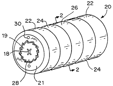
Figure 1 depicts a cylindrical embodiment of the disk
implant of the present invention. The disk implant 20
shown in that figure is comprised of a strong, thin non
porous material. Suitable materials for the disk implant
include modified carbon, titanium, steel, metals and/or
metal alloys having a memory (see below), physiologically
inert and/or medically compatible polymers such as a
20 urethane or DELRIN~ polymer, or any generally rigid,
biologically compatible material used for surgical
implants. It is also useful to use a material which is
compatible with magnetic resonance imaging (MRI)
procedures. The disk implant 20 is comprised of a
plurality of longitudinally aligned sections, or subunits
22, 24 and 26, and a screw 28 to which each section is
mounted (as described below) is turned to cause
differential, radially outward expansion of subunits 24 and
26. The subunits 24 and 26 are preferably comprised of a
material capable of maintaining spring tension and are
mounted to and wound around an elongate longitudinal axis
in the form of central rod 25 (see Figs. 2 and 3) integral
with screwhead 28. Because of this structure, each of the
subunits is conveniently referred to as including a coiled
member as identified at reference numeral 32.
WO 92/14423 . PGT/US92/Oi397
Each coiled member 32 is mounted to central rod 25 by
welding, riveting, or by other manner depending upon the
materials) comprising the sheet 32 and central rod 25 as
known in the art. In the preferred embodiment shown in
Figures 1-4, the central rod 25 is provided with a flat 23
to provide a stable surface for mounting of the member 32
thereto by, for instance, welding. At the other, free end
of each coiled member 32, the coiled member 32 is beveled
as at reference numeral 33 so as to provide a smooth,
generally~round exterior surface on each of the subunits 24
and 26 and to facilitate the sliding of the free end of
coiled member 32 along the outside surface thereof as the
subunits 24 and 26 are expanded radially outwardly as
described belo4:.
A Phillips head-type slot 18 is provided in the
screwhead 28 for rotation of the rod 25 as described below,
and the head 28 is provided with a plurality of teeth 19
for interdigitating with the reciprocal cavities in the
lock nut 21 to prevent undesired rotation of central rod
25. The Allen screws 30 are loosened to force lock nut 21
away from the end surface 27 of subunit 22 so that the
teeth 19 on the head 28 of central rod 25 are disengaged
from the cavities in lock nut 21 to allow rotation of
screwhead 28 and rod 25. Alternatively, either or both of
rod 25 or lock nut 21 is comprised of a resilient,
medically compatible polymer material which allows rotation
of the teeth 19 past the cavities in lock nut 21 in one
direction but not the other. The expanded shape of a
section of the disk implant 20 is shown in Figure 2.
Turning screwhead 28 and central rod 25 using the slot
18 expands the sections 24 and 26, which remain expanded
due to the interaction of the teeth 19 and the cavities in
lock nut 21 and the compression of the implant 20 between
the bodies of the vertebrae above and below the implant 20
once inserted into the disk space. In other words,
WO 92/14423 ~ ~ ~ ~ ~ ~ PCT/US92/01397
7
engagement of the free end of coiled member 32 by the
adjacent vertebrae prevents the slipping of the free end of
the coiled member 32 around the outside circumference of
implant 20 such that members 32 do not "re-wind" after
being expanded.
As shown in Figure 3, central rod 25 is provided with
a portion 29 approximately mid-way between the ends thereof
having a larger diameter than the rest of the central rod
25. By use of the central rod with sections of different
diameters and/or thicknesses of the cylindrically wound
member 32, the subunits 24 and 26 are differentially
expanded. Turning screw 28 allows for maximal expansion of
the subunit 26 and moderate expansion of the subunit 24
because the member 32 comprising subunit 26 is mounted to
the rod 25 on the portion 29 of larger diameter while each
of the members 32 comprising subunits 22 and 24 is mounted
to central rod 25 between the portion 29 and the subunits
22. Turning the central rod 25 uncoils the members 32
because each member 32 is attached to the central rod 25.
Figure 4 illustrates the cylindrical disk implant 20
in its radially expanded form. Once expanded, the implant
cannot be removed from the disk space except by turning the
allen screws 30 to either back out or remove lock nut 21,
thereby allowing rotation of rod 25.
Referring now to Figures 5 and 6, an alternative
embodiment of the implant 20 is shown at reference numeral
56. Implant 56 is comprised of a single piece of metal,
such as a titanium alloy, or medical grade polymeric
plastic, such as DELRIN~', which is resilient and has a
memory for the shape in which it is molded, shown in Fig.
6. Implant 56 is molded in the same generally el~~.gate,
cylindrical shape as the implant 20 shown in Figs. lw , but
is molded in a shape in which the middle portion 58 thereof
is normally expanded radially outwardly from the central
axis of the cylinder. An elongate screw 60 is provided
WO 92/14423 - ,~ ' . PCT/US92/01397
f
_8_
having two sets of threads 62 and 66 thereon, the former
for engaging the threads 68 formed in the bore 70 extending
longitudinally through implant 56, the latter for engaging
a similarly formed set of threads located in the bore 70 at
the other end of implant 56 and therefore not visible in
Figures 5 and 6. A slot 72 is formed in the head 74 of
screw 60 for turning screw 60 to move the opposite ends 76a
and 76b of implant 56 away from each other, thereby
extending implant 56 and decreasing the radially outward
expansion of the middle 58 thereof as shown in Fig. 5 for
insertion into the disk space. Longitudinal slots 75 are
molded into implant 56 to form ribs 77 which flex to allow
the extension and outward expansion of implant 56 in this
manner.
As noted above, the instability of prior implants once
inserted into the disk space is problematical, and Fig. 7,
showing the implant 56 in place relative to the body 78 of
an adjacent lumbar vertebra 80 illustrates how the
apparatus of the present invention overcomes this
limitation of prior implants. The implant 56 is inserted
into the disk space in an anterior-posterior (A-P)
orientation, the dorsal spine 82 of vertebra 80 being
pointed posterially. As clearly shown in Fig. 7, when so
positioned, implant 56 occupies only a portion of the
surface area of the vertebral body 78, the remainder of the
area being occupied by that portion of the intervertebral
disk (not shown) which is not removed during the diskectomy
procedure (or, in a fusion procedure, this area is packed
with cancellous bone chips). Access to that area is from
the posterior aspect of the disk medial to the implant. In
addition, the periphery 88 of vertebral body 78 is, ~as
described above, thicker than the central portion 90 of
body 78, further limiting access and creating an uneven
surface on which the body 78 bears on the implant.
However, because of the expansion of only the middle 58 of
WO 92/1.1423 a .i PCT/US92/0139'7
~2~~~~L3~.
.,,
_g_
implant 56, the implant 56 is stable in the A-P orientation
shown. Once implanted, the screw 60 is backed out of the
bore 70 in implant 56 and implant 56 assumes the shape
shown in Figs. 6 and 7.
Figure 8 depicts a rectangular disk implant 31
constructed according to the present invention. Turning
Phillips head 39 of screw 42 encapsulated in a sheath 44
(best shown in Fig. 9) formed in the hinged members 34 and
36 forming intermediate subunits in the same manner as the
subunits, or sections, 24 and 26 of implant 20 causes the
radially outward expansion of superior hinged members 34
superiorly and inferior hinged members 36 inferiorly.
Although shown in Figures 8 and 9 with two of the hinged
members 34 and 36, it will be understood by those skilled
in the art who have the benefit of this disclosure that the
plug, or implant, 31 may be provided with four, eight, or
even more of the hinged members 34 and 36 as shown at
reference numerals 92 and 94 in Figure 10 and numeral 41 in
Figures 11-13. The expanded shape of the rectangular disk
plug 31 is illustrated in Figure 9. Hinged members 34 and
36 are secured to an end cap or subunit 33 by hinge 38 and
to each other by hinge 46. Upon rotation of screw 42 using
a conventional screwdriver and the Phillips head slot 39,
the end caps 33 are drawn closer together by movement along
the threads of screw 42. To insure that the members 34 and
36 expand radially outwardly from screw 42, the ends 48 of
each respective member 34 and 36 abutting the end caps 33
are angled so as to create a force vector outwardly away
from screw 42 when end cap 33 exerts pressure on the
surface 48, the hinge 38 being mounted in the acute angle
formed by surface 48 and end cap 33.
In one embodiment (best shown in Figures 11-13 and
discussed below), the tendency of this force vector to
cause the members 34 and 36 to expand is increased by
angling the face 50 of one member 34 or 36 in the same
WO 92/14423 ;.~ * ~k , PCT/US92/01397
'' ~ ~,..:
-lo- w
direction as the angle in the surface 48. The surface 52
of the opposed member 34 and 36 is similarly angled, but
with a bearing surface'S4 formed therein that is angled in
the same direction as the angle in surface 48 and face 50 v '
so that the face 50 rides upwardly onto bearing surface 54
to translate the opposed, end-to-end force vectors applied
to end caps 33 by rotation of screw 42 into a force vector
having a radially outward (from screw 42) component. By
referring to Figures 11-13, it can be seen that the
radially outward expansion of the middle portion of implant
31 caused by rotation of the screen 42 effectively simulates
the opening of two opposed umbrellas, and the particular
embodiment shown in those figures may be conveniently
referred to as having a "double umbrella" configuration.
A threaded lock nut 40 is inserted over Phillips screw
head 39 (see Figure 8). Lock nut 40 prevents the members
34 and 36 from moving once expanded. Removing lock nut 40
provides access to screw head 39 to allow members 34 and 36
to return to the position shown in Figure 8.
The above-referenced, double-umbrella configuration of
the implant of the present invention is illustrated at
reference numeral 88 in Figure 10. In this embodiment, the
hinged members 92 and 94 are mounted on pivot pins 96 to
the first and second end members 90 and 98, respectively,
as well as to each other, most of the pins 96 and all but
two sets of the hinged members 92 and 94 being omitted from
the figure for purposes of clarity. The pivot pins 96
which mount members 92 and 94 to the ends 90 and 98 are
received within the bores 100 and 102 formed in each end
member 90 and 98, the bores 100 and 102 being numbered
separately to draw attention to their arrangement on the
end members 90 and 98. The ears 104 on hinged members 92'
and 94' are longer than the ears 106 on hinged members 92 "
and 94 " and the bores 100 for receiving the pivot pin 96
are located closer to the end surface 108 of end member 90
' W092/1~1423 ~ ~,~ ~ ~~ ~~ :~ PC.T/US92/0139'1
r,?
E:SN ~~
-11-
(and the corresponding end surface of end member 98 at the
opposite end of implant 88) than the bores 102. By this
arrangement, the strength of the implant 88 is
significantly increased.
Expansion of the middle portion of implant 88 is
accomplished by turning the screw 112 using the hex head
114 formed at one end thereof, the other end of screw 112
being received by the threads 115 formed in the second end
member 98. To increase the tendency of the hinged members
92 and 94 to expand in the radially outward direction, the
holes in the hinged members 92 and 94 in which pivot pins
96 reside are offset along the longitudinal axis of implant
88. The offset holes are better shown in Figure l0A in
which one pair of the members 92 and 94 is shown in side
view removed from implant 88. The direction of expansion
is shown by the arrow 95 in Figure l0A and, as can be seen,
the center holes 97 are offset outwardly (e.g., in the
direction of arrow 95) relative to the holes 99 at the ends
~of hinged members 92 and 94 (e. g., in the ears 106).
A lock nut 116 having threads 118 formed in the
outside surface thereof is received by the threads 120
formed in the bore 122 in end member 90 through which the
screw 112 is received for preventing undesired rotation of
screw 112. Lock nut 116 is provided with a hex slot 124 to
facilitate insertion and/or removal and hex slot 124
extends all the way through lock nut 116 and is of large
enough size that a hex key can be inserted through slot 124
and into hex head 114 for turning screw 112 without
adjustment of lock nut 116.
Another embodiment of the double-umbrella
configuration of the implant of the present invention is
shown at reference numeral 41 in Figures 11-13. As is the
case with the implant 88 shown in Figure 10, the implant 41
is generally cylindrical in shape, yet utilizes the hinged
member 34 and 36 construction of implant 31 shown in
WO 92/14423 , ~ ° '~.~~j ~ PCT/US92/01397
.~.~.~'3 a . . ~ta,~:
-12- _.
Figures 8 and 9. Figure 12 shows a projected view of the
disk implant 41 shown in Figure 11 having the members 34
wind 36 cut in section. This view shows how the hinged ,
members 34 and 36 fit together in the unexpanded position '
due to their beveled sides 64, giving the implant 41 its ,
generally cylindrical shape. The sides 110 of the hinged
members 92 and 94 of implant 88 are similarly beveled
(Figure 10).
All of the disk implants of the present invention are
expandable in the middle portion, i.e., the portion
intermediate the ends, to contact substantially the entire
anterior-posterior dimension of the disk space against the
vertebral bodies as described above in connection with the
description of Figure 7. If a complete intervertebral
fusion is being performed, the plug is used in conjunction
with intervertebral cancellous bone packing. Because of
the support provided by the plug, until fusion is
established, the cancellous bone pieces have a better
chance of fusion due to the presence of the implant, and
the bone pieces and the disk. implant have a better chance
of staying in the intervertebral disk space.
Alternatively, the plug is used to maintain the spacing
between vertebrae and can be used in conjunction with
intertransverse posterior lateral fusion. In short, the
implant acts as a physiological support for the rest of the
patient's life or until a bone fusion is established.
The disk implant of the present invention may have
additional indications, e.g. short segment scoliosis, where
the curvature of the spine can be corrected by distracting
the vertebral bodies on the inside of the curvature. By
expanding the middle portion of the plug inside the disk ,
space, the vertebral bodies are distracted, thereby helping
straighten the spinal column.
If no bone graft is planned, diskectomy can be made '
minimally through one side exposure so that when the disk
w0 92/14423 ~ 1 ~ '~ ~ .~.~ ~ ~ ~ PCT/US92/01397
~:z .
-13
plug is inserted and expanded, it will occupy the empty
space. Because there is no further movement at this disk
space, the chance of recurrent disk herniation is
minimized. Also, the likelihood of recurrent disk
herniation due to opening and closing of the space on the
side of the diskectomy is reduced because the disk plug
closes this mouth. Consequently, in addition to the
advantages of a one sided, simple diskectomy, the risk of
recurrent disk herniation can be reduced.
The cylindrical 20, 41, 56, and 88 and rectangular 31
implants are inserted after a simple diskectomy.
Ordinarily, the size of the disk implant is approximately
2.5 to 3.5 centimeters in length and 1.0 to 1.5 centimeters
in height and width. The same plug in smaller dimensions
is used in thoracic and cervical levels where indicated.
By reference to the figures, it can be seen that both
the rectangular and the cylindrical implants have the
common feature of being expandable in the middle without
changing the diameter of the dimensions of the two ends.
Consequently, surgery is performed as in simple diskectomy,
and the disk is exposed through a small laminotomy. The
disk material is removed and any nerve root compression is
corrected. The posterior longitudinal ligament and disk
cartilage are removed until the vertebral surfaces are
exposed above and below the disk space. The shape of the
disk space determines whether the disk plug used is
cylindrical or rectangular. The disk plug is then inserted
and hammered into place so that the anterior end of the
disk plug almost touches the anterior longitudinal
ligament. Subsequently, using a Phillips screwdriver, the
posterior screw end is turned. This implant method also
gives good distraction to the vertebral bodies. In the
case of simple disk problems, no further treatment may be
required.
WO 92/14423 a ~ ''PCT/US92/Oi39'7
;~..~ :~:.:'s,..'' :.- , ~'':'~;
-14-
When used in interbody fusion, cancellous bone chips
are made into very fine particles and pumped into the disk
s~>ace medial to the disk plug and packed into the space.
The posterior longitudinal ligament is intact to the '
opposite side and to the center of the disk space. These
cancellous bone chips are held tightly in place. Since the
mouth of the disk space is closed with the disk plug, the
risk of the cancellous bone chips coming out is minimized.
Also, the disk plug prevents the opening and closing of the
disk space, thus preventing the bone chips coming~out. If
necessary, a small amount of a physiologically compatible
adhesive of a type known in the art is applied over the
cancellous bone chips just medial to the disk plug to close
off the remaining portion of the opening of the disk space.
The patient should be able to ambulate soon after the
surgery because of the stability given by the disk plug.
Before narrowing of the disk space occurs, the cancellous
bone chips will have started the fusion process.
If a posterior lateral intertransverse fusion is
desired, this procedure is also done in conjunction with
the middle expandable disk plug. The disk plug is applied
as explained above and the posterior lateral fusion
performed. Since the disk plug provides stability to the
spine until the posterior lateral fusion is solid, the
patient can ambulate soon after the surgery. This
procedure also prevents the disk space narrowing, which is
a common problem with posterior lateral fusion.