Note: Descriptions are shown in the official language in which they were submitted.
2 1 ~ 3
APP~RA~U8 FO~ R~ vlN~ AND DI8~L~YIN~
COLOR TE~E~ O~ 8I~ Xa~I~ D~BR~N~ FORM~8
D OF T~ INV~N~I~N
The present invention generally relates to the color
television field, and more particularly, is directed to a color
television receiver which is capable of receiving and displaying
color televi~ion ~ignals broadca~t with different transmission
specification~ and formats. The receiver pe~its accurate
reproduction and display of the color picture information contained
in the received television signal without regard to its
transmission speci~ication or ~ormat.
r -~ D 0~ ~E T~V~N~O~
In ~he NTSC teleuision signal system, which i8 the system
presently in use in the United States ,and in many ok~er countries,
the tr~n~ 3ion specifications and format wer~ esta~lished in
order t~ maxi~ize the amount of red ~R), green (G) and blue (B)
primary col~r in~or~ation which can be transmitted in the
tel~vision signal. Thus, the NTSC specifications and format
provide wide chromaticity ranges in order to insure transmission of
.
. , .
, .: , , ~ .
~ : ~ . - .
~ .
' ~ ' .:: ' '' ~
4 3
full color content for the television image.
Television rec~ivers known in the prior art reproduce the
color image con~ained in the television signal by adding and mixing
the red, green, and blue primary color information extracted ~rom
the television signal. However, the chrom~ticity ranges of a
typical television receiver is narrower than the chromaticity
ranges present in the received television signal. Thu~, full and
faithful reproduction of the ~olor picture information contained in
the television signal is not possible in televi ion receivers known
in the prior art.
Figure 1 is a CIE (Commission International de Enluminure)
chromaticity diagram illustrating the red, green and blue primary
color chromaticity values for the NTSC sy~tem, the phosphor in a
cathode ray tube (CRT) used in the typical television receiver and
the color filter in a liquid crys~al display device (LCD), also now
commonly used in small portable television receivers and large
projection-type television displays. The NTSC chromaticity values
are represented by the ~Ache~ line, the CRT chromaticity values are
represented by th dot-dash line and the LCD values are represented
~y the solid line. The chromaticity values charted in Flgure 1 are
set forth below in table form: .
, .. ~ .. .
. . ~ ,
" ~".
2~0~3
N~SC CR~' LCD
X Y X ~ X Y
R: 0.670 0.330 0~657 0.338 0.613 0.334
G: 00210 0.710 0.2~7 0.609 0.233 0.627
B: 0.140 0.080 0.148 0.054 0.140 0.079
The outer bold line in Figure 1, and associated numbers at the
indicated points on the line, illustrate the spectrum locus and
wave-lenqths (nm). In the NTSC system here, C light having a color
temperature of 67~4 K is used as a referenc2 white light W with the
following chromaticity:
W : X = 0.3101, Y = 0.3163
In the NTSC system, if the chromaticity values ~or the three
primary color~ for the display ~CRT or LICD) in the receiver are set
to the s~me as the NTSC values, the co.lor picture information in
the tran3mitted television signal can be ~aithfully reproduced on
the receiver display by setting the reierence white light to the
c~romaticity of C light. Howev~r, a color television receiver must
also b~ capable of receiving and displaying black and white
television signals. Therefore, in order to achieve the requisite
compatibility with black and white television broadcasts, a white
color light with higher chromaticity values than C light must be
x,. ~
, i
: ~ ' ' ~ , ~ .......... . .
;
' . '
: : ~
2104~3
-4
used as the reference.
In addition, the chromaticity values for the primary colors
for a television receiver depends on the phosphor chro~aticities oP
the CRT or LCD which, as described above and shown in Figure 1, are
different than the chromaticity values for the primary colors for
the NTSC system. Therefore, if corrections are not made ~or the
differences between the NTSC and receiver chro~aticity values,
color errors will result and the color picture information
contained in the television signal will not be faith~ully
reproduced on the display in the receiver.
Moreover, and as also discussed above, the chromaticity ranges
of the CRT and LCD are narrower than the NTSC chromaticity ranges.
Thus, the color reproduction range of the television receiver i5
not brvad enough to reproduce all o~ the color information
contained in the ;nc ing television signal~ The~efore, even when
the appropriate color corrections are made with respect to
differencs~ in the NTSC and display chromaticity ~alues, the
receiver is still not capable of faithful reproduction of every
color received in the inc. ;ng television signal.
The types of color reprcduction errors discus~ed above are
also referenced on page 959 in the book entitled "The New Color
-... : :: ... . . ... - :
.. .~ . . . .
2 1 ~ 3
Science Handbook" which was published in Japan.
Figure 2 i~ a UV chromaticity diagram showing the color
reproduction errors described above and referenced in the above
mentioned handbook. The solid line triangle in Figure 2 indicate~
the chromaticity range for the primary colors of the NTSC system on
the transmis~ion side of the television signal. The dashed line
triangle illustrates the chromaticity range of the primary coiors
of the CRT phosphor at the receiver. Note that while the NTSC a~d
CRT ranges greatly overlap, the NTSC range is slightly larger and
each of its values are shifted from the corresponding values in the
CRT range. The graph in Figure 2 is obtained by calculating the
color reproduction error based on the differences between the NTSC
ancl CRT chromaticity ranges. An example of some of the NTSC
chromati~ity values are shown by the dots in Figure 2. In order to
correct color reproduction errors in the display, these values must
be shifted in order to bring them into a corresponding point in the
CRT chromaticity range as indicated by the arrows in Figure 2.
In CRT television receivers and color cameras, linear matrix
circuits are used to correct color reproduction errors. Figure 3
is a block diagram showing a linear matrix oircuit which corrects
such color reproduction errors. The G (green), B (blue) and R
.. ,.,. - ,~ -, : .
. ~
-6-
(red) primary color signals are supplied to input terminals 1, 2
and 3, respectively, and to gamma cancellation circuits 4, 5 and 6
so that transmission gamma is cancelled by removing the ga~ma
correction which was added to the signal on the image transmission
side.
The output signals ~rom gamma canc~llation circuits 4, 5 and
6 are supplied to matrix circuit 7 which is formed of coe~ficient
circuits 8 to 16 and adders 17 to 1~. Matrix circuit 7 multiplies
the supplied R, G and B signals by respective corre~tion matrix
coefficients and then adds them together. Coefficient circuits 8
to 16 can be formed o~ simple circuits using resister~ as is known
in the art. Gamma addition circuit:s 20, 21 and 22 add the
transmission gamma to the respective corrected R, G and B color
signals and outputs them via terminal~s 23, 24 and 25 as primary
color signals Rl, Gl, and Bl. In this way, color reproduction errors
are r~ :ved and approximatQly the same colors as in the transmitted
image can bs re~Lo~uced at the receiver. However, the correction
is possible only for colors in the region in which the solid line
triangle and the ~he~ line triangle in Figur~ 2 overlap each
other.
,~.. ... - . , - , ~ -
. . ;
: . .:
2 ~ 4 3
Recently, there have been test broadcasts of a high definition
television (~DTV) signal format which is capable of displaying high
quality television images. Taking into account the popularity of
the existing NTSC television system, and the large installed base
of such equipment, television receivers which are capable of
receiving images in both the NTSC and HD~Y system formats are being
made commercially available. ~owever, the transmission
specific~tions of an HDTV system are different from those o~ an
NTSC system. In the HDTV transmission specification and format,
th~ R, G and B primary color chromaticîties are as follows:
R: X - 0.640, Y = 0.330
G: X = 0.300, Y - 0.600
13: X = 0.150, Y = 0.0~)
Also in the HDTV specification, D~ lis~ht is used as a reference
white color and its chromaticity W Ls as follows:
~ : X = 0.3127, Y = 0.3290
Figur~ 4 is a ClE chromaticity diagram showing the NTSC
specification values and the HDTY specification vales of thP
respective R, G and B primary color chromaticities. As Figure 4
indicates, the chromaticity value ~or G in the NTSC syst~m is
.j, . ~ - .
:.
.
'' ': ~
-
~4~43
greatly dif~erent than the chromatic:ity value for G in t~e HDTV
system. Note, however, that the chromaticity value for G in the
HD~V system is comparatively close to the chromaticity value for G
in CRT and LCD displays (see Figure 1). There~ore, in a television
receiver which uses a C~T or LCD, there is comparatively little
color reproduction error when receiving and displaying a HDTV
broadcast. There is, however, a likelihood of large color
reproduction errors when receiving an NTSC broadcast as is apparent
from Figure 1.
When correcting color reproduction errors for one system in a
television receiver which is capable of receiving multiple system
formats ~such NTSC and HD~V) in which the three primary color
chromaticity values differ from one system to the other, color
reproduction errors in the other systems cannot be corrected~
Television P~OYLamS produced by the HDTV system and commercial
feature ~ilms are sometimes bro~r~cted using the NTSC system.
Faature ~ usually are produced in accordance with
specifications established by the Society o~ ~otion Pictura and
Television Engineers (SMPTE~. The HDTV system also i5 set to
conform to SMPTE specifications.
Eigure 5 is a CIE chromaticity diagram showing the
,' :
', . ' ''''~;' :' ~ ' '
2 1 ~
.9_
transmission primary color chromaticity values for both the SMPTE
and NTSC systems. As is apparent from Figures 4 and 5, the
transmission primary color chromaticity values for the HDTV system
approximately coincides with those of the SMPTE system. Also, the
PAL and SECAM television signal transmission systems are nearly
standardized to the EBU specifications~ The transmission primary
color chromaticity values for thase systems also approximately
coincide with those of the HDTV system
There is presently known in the art an HDTV to NTSC system
converter which enables reception of HDTV broadcasts on a standard
NTSC system television receiver. With such a converter, or other
equipment having similar functions as that of the converter, it is
possible to also convert other signal f'ormats, such as SMPTE, PAL
and SECAM to NTSC for display on a standard NTSC receiver. However,
the transmission gamma of the NTSC syste~ dif~ers from the
transmission ga~ma of any one of the other systems.
Figure 6 is ~ ~raph illustra~ing transmission gamma. The
solid line shows the gamma curve of the SMPTE system and the dashed
line shows the gamma curve of the NTSC system (~ = 0~45~ s shown
in Figure 6, the black side values in particular differ between the
NTSC and the SMPTE systems. Due to the difference between the
-. ~ . : .
.
CA 02104443 1998-02-27
-10-
gamma curves, the rendering of the black gradations sometimes is unnatural
depending on the signal source of the broadcast program. For instance, even
within the same broadcast program, the gradation rendering differs
according to the difference in the signal source, namely in accordance with
5 the specification under which the program was produced.
In addition to television receivers which use a CRT or liquid crystal
display, recently projection-type color television receivers have been
developed in order to provide large-screen viewing. Projection-type
television receivers uses a plurality of liquid crystal panels capable of
modulating light colors. Such a receiver is referred to at pages 415 to 418 in
"SID 91 DIGEST."
SUMMARY OF THE INVENTION
Various aspects of the invention are as follows:
Television receiving apparatus for receiving and displaying television
signals distributed in a plurality of formats, said television apparatus
comprising:
input means for receiving said television signal;
color error correction means coupled to said input means for correcting
color reproduction errors associated with the received television signal and
providing a corrected television signal;
display means coupled to said color error correction means for
receiving said corrected television signal and displaying a television image in
accordance with said corrected television signal, said display means having a
reproduction chromaticity range sufficiently wide to include essentially all of
the transmission chromaticity range in said received television signal; and
control means coupled to said color error correction means for
controlling the operation of said color error correction means in accordance
with the format of said received television signal.
Television receiving apparatus for reproducing a colored image
transmitted by a television signal in any one of a plurality of systems with
differing transmission specifications, said apparatus comprising:
CA 02104443 1998-02-27
-lOa-
input means for receiving a television signal;
detection means coupled to said input means for receiving said
television signal and detecting which system of said plurality of systems is
5 used for said television signal and generating a control signal which indicates
the system of said television signal;
color error correction means for correcting color reproduction errors
associated with said received television signal in accordance with said control
signal and providing a corrected television signal;
white color setting means for setting a display white color temperature
in accordance with said control signal and the system of said television
signal; and
display means having a reproduction chromaticity range wider than
the transmission chromaticity ranges of each of the systems of said plurality
15 of systems, said display means displaying a television image in accordance
with said corrected television signal and said display white color
temperature.
A method for reproducing a color image transmitted by a television
signal in any one of a plurality of systems with differing transmission
20 specifications, said method comprising the steps of:
receiving said television signal and providing a received television
signal;
detecting which system of said plurality of systems is used for said
television signal and generating a control signal which indicates the system of
25 said television signal;
correcting color reproduction errors associated with the received
television signal in accordance with said control signal and providing a
corrected television signal; and
driving a display device having a reproduction chromaticity range set
30 sufficiently wide to include the transmission chromaticity ranges of said
plurality systems in accordance with said corrected television signal and
displaying said colored image.
By way of added explanation, in accordance with an aspect of this
invention, a television apparatus is provided for displaying an image
35 transmitted in accordance with a plurality of different transmission
specifications and formats. The apparatus includes a color correction device
CA 02104443 1998-02-27
-
-lOb-
for correcting color reproduction errors associated with the received
television signal. The reproduction errors are due to differences in the
primary color chromaticity values between the transmission side and the
reception side of the television signal. The errors must be
CA 02104443 1998-02-27
-11-
corrected in order to provide faithful reproduction of the color picture
information contained in the television signal for display at the receiver.
A control device also is provided for controlling the operation of the
error correction device in accordance with the particular specification and
5 format of the received signal. The corrected primary color information is
provided to a display for display of the television image with full and
accurate color reproduction. The displayed image has reproduction
chromaticity ranges which are sufficiently broad to include essentially all of
the transmission chromaticity ranges of the various transmission systems
10 such as NTSC, HDTV, SMPTE and the like.
It is therefore an object of an aspect of the present invention to provide
a television apparatus by which the colors on the transmission side of the
system can be faithfully reproduced even when receiving a television signal
from multiple systems with differing transmission specifications and formats.
An object of an aspect of the present invention is to provide a display
apparatus which can provide natural gradation rendering when using
different television system specifications and formats.
The above and other objects of the present invention will
2 1 ~ 3
-12-
become obvious upon an understancling of tha illustrative
embodiments described below. Various advantage~ which are not
referred to herein will also occur to those skilled in the art upon
employment of the pr~sent invention in practice.
BRI~ D~8CRI~ION OF T~ DRAW~NG8
Figure 1 is a CIE chromaticity diagram howing the three
primary color chromaticities o~ an NTSC system, a CRT phosphor
display screen and an LCD display screen.
Figure 2 is a W chromaticity diagram showing eolor reproduc-
tion errors.
Figure 3 is a block diagram illustrating a linear matrix
circuit which corrects color reproduction errors.
Figures 4 and 5 are CIE chromaticity diagrams showing the
three primary color chromaticities of an HDTV system and an SMPTE
system, respectively.
Figure 6 i~ a graph showing the gam~a curves of an NTSC and
SMPTE system.
Figure 7 is a schematic block diagram showing a projection-
type color television receiver to which an ~ hg~i ~nt of the
present invention is applied.
Figure 8 i~ a graph showing the light emission distribution
-~
~ .
! :
,,
" ' ' ~
2110~3
characteristics of a metal halide lamp.
Figure 9 is a graph showing the integrated transmissivity
characteristics of dichroic mirrors.
Figure 10 is a graph showing the light output characteristics
of dichroic mirrors.
Figure 11 is a CIE chromaticity diagram showing the three
primary color chromaticities of a television receiver in accordance
with one ~ ho~i ?nt of the present invention.
Figure 12 is a block diagram showing the drive circuitry used
for driving the liquid crystal panels shown in Figure 7 according
to one embcdiment of the present invention.
Figure 13 is a block diagram showing the circuitry which
generates control signals in accordance with the present invention.
Figure 14 is an illustration of a display screen showing a
letter-box display.
Figure 15 i5 a block diagram showing a linear matrix circuit
used for another A~ho~iment of the pre~ent invention.
DE~T~,R~ DE~C~IPTION OF T~ PREFERR~D EW~ODIMEN~
Representative ~ ho~i ents of the present invention will now
be explained with reference to the accompanying drawings.
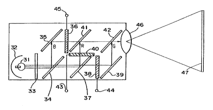
Figure 7 is a line drawing illustrating a projection-type
21p 1~3
color television receiver to which an embodiment o~ the present
invention can be applied. In this embodiment, the projection type
television receiver shown in Figure 7 is capable of receiving and
displaying television picture inPormation in both the NTSC and HDTV
formats.
The receiver of Figure 7 operat~s in the following manner. A
white lamp 31 emits a high intenRity white light. A metal halide
lamp which has superior color rendering can be used ~or white lamp
31. A reflector 32 is provided on the periphery o~ white lamp 31
and is the ~ocal point of the white light. The reflecting surface
of reflector 32 is formed in the shape of a paraboloid so that the
light from white lamp 31 is re~lected and directed in a parallel
beam in a direction perpendicular to the reflecting surface of
reflector 32.
~ W -IR filter 33 is po~itioned :Ln ~ront of white lamp 31.
This filter eliminates unwanted light from the beam re~lected from
reflector 32. The reflQcted beam which p~ssPs through filter 33 is
incident upon dichroic mirror 34. Dichroic mirror 34 reflects, or
~ilters out, blue light while passing other colors of light.
A mirror 35 is positioned on the beam axis of the blue light
re~lected from dichroic mirror 34 and in turn reflects this light
.. . . .
.. ... . . .
. .
:
210~3
-15-
to blue light liquid crystal panel 36 which is positioned on the
beam axis of the light reflected from mirror 35. A dichroic mi.rror
37 is positioned on the beam axis of the light which pa~sed through
dichroic mirror 34, and it reflects or filters out, red light while
passing green light to green light liquid crystal panel 38. The
red light reflected by dichroic mirror 37 is incident upon a liquid
crystal panel 40. Thus the three liquid crystal panels 40, 38 and
36 recei~e an R signal, a G signal and a B signal, respectively,
via terminals 43, 44 and 45 from a drive circuit which will be
discussed below. At the same time, liquid crystal panels 40, 38
and 34 are supplied with, and driven by, sc~nning signals from a
drive circuit so that each colored beam is modulated and
respectively emitted a~ an R imag~ beam, a G imaqe bea~ and a B
image beam from their emission ~urfaces.
A synthesizing mirror 41 is positioned on both beam axis of
the light emitted from liquid crystal panels 40 and 36. Mirror 41
optically synthesizes and transmits the B image beam and the R
image beam from liguid crystal panels 3S and 40. A mirror 39
reflects the G image beam from liquid crystal panel 38. This
reflected beam is directed to another synthesizing mirror 42.
Synthesizing mirror 42 optically synthesizes the image beam from
. : ,
.
.,. . : - -
2104~3
-16-
synthesizing mirror 41 and the G image beam from mirror 39 and
directs them to a projection lens 46. Projection lens 46 is
designed so that the incident beam is magnified and projected onto
a screen 47.
Figure 8 is a graph showing the typical light emission
distribution characteristics for the metal halide lamp us~d for
white lamp 31, where wavelength is plotted along the horizontal
axis and relative luminous intensity i5 plotted along the vertical
axis. As shown in Figure 8, a continuous spectrum of light i8
emitted from white lamp 31. This continuous spectrum o~ ligh~ is
resolved by dichroic mirrors 34 and 37 in order to obtain the three
primary color beams, blue, red and green.
Figure 9 is a graph showing the integrated transmissivity
curves of dichroic mirrors 34 and 37, where wavelength is plotted
along the horizontal axis and trAn~ ;ssivity is plotted along the
vertical axis. In the graph, the dot-dash line (B~, the solid line
~R) and th~ h~ line (G) show that wavel~ngths in the vicinity
of blue, red and gr~en light, respectively, can be obtained.
Figure 10 is a qraph showing the light output curves of
dichroic mirrors 34 and 37, where wavelength is plotted along the
horizontal axis and quantity of light emitted is plotted along the
: , . .
:: : :, ' ~
. ~ .
2~0~3
-17-
vertical axis.
The light from white lamp 31 is split into the three primary
colors having the characteristics shown in Figure 10 by passing the
light through dlchroic mirrors 34 and 37 as discussed above. When
liquid crystal panel~ 36, 38 and 40 are in the transmission state,
image beams with the same characteristics ~s shown in Figure 10 are
emitted. Thus, display of the three primary color chromaticities
are determined by the light-emitting characteristics of white lamp
31 and the transmissivity characteristics of the optical c-omponents
of dichroic mirrors 34 and 37. Display of the three primary color
chromaticities also vary due to the optical component
characteristics of W-IR filter 33, pro~ection lens 46 and mirrors
35, 39, 41 and 42. However, variations due to these components are
small and are not dominant factors.
Control of the display of the three primary color chromaticity
values can be accomplished relatively easily by suitably setting
the tr~n~ sivity characteristics of dichroic mirrors 34 and 37.
For example, when it is desired to project a color on the spectrum
locus in a CIE chroma~ici~y diagram, a dichroic mirror having
narrow band filter characteristics and which only transmits light
of that wavelength is used. In this embodiment, the light-emitting
~ .
: .
'
'
210~4~3
characteristics of white lamp 31, and the transmissivity
characteristicR of dichroic mirrors 34 and 37, are set for the
reproduction range of the three primary color chromaticity values
for both the NTSC and HDTV systems.
Figure ll is a CIE chromaticity diagram showing the
chromaticity values for displaying the three primary color
chromaticities which are established by settlng the optical system
illustrated in Figure 7 so that the color reproduction range is set
to the chromaticity range shown by the thick-line triallgle, i.e.,
the range which includes the NTSC and NDTV formatsO
Figure 12 i~ a block diagram showing the drive circuitry which
upplies the R, G and B image signals to terminals 43, 44 and 45 in
Figure 7. As shown in Figure 12, respective R, G and B original
image coLor signals are supplied to input terminals 51, 52 and 53
and in turn, to linear matrix circuits 54 and 55. Matrix circuits
54 and 55 differ fro~ the matrix circuit in Figure 3 only with
respect to th~ correc~ion matrix coefficients in coefficient
circuits 8 to 16 and the characteristics of gamma addition cixcuits
20 to 22.: In other words, linear matrix circuit 54 sets the
correction m trix coefficients so that the three display primary
color chromaticities agree with the three transmission primary
.
.- ' . ' '
2104~
--19--
color chromaticities of an NTSC system. Linear matrix circuit 55
also sets the correction matrix coe~icients so that the three
display primary color chromaticities agree with the three
transmission primary color chromaticities of the HDTV system.
A switching circuit 56 is controlled by a control signal from
terminal 58. Circuit 56 selects either the R, G and B signals from
linear matrix circuit 54, or the R, G and ~ signals from linear
matrix circuit 55, and outputs them to a video signal processing
circuit 57. The control signal supplied to terminal 58 indicates
whether the rece:ived signal is an NTSC or HDTV ~ormat signal. When
receiving an NTSC format signal, swil:ching circuit 56 selects
linear matrix circuit 54 and when receiving an HDTV format signal,
switching circuit 56 selects linear matrix clrcuit 55.
Video signal processing circuit 57 performs contrast
adjustment, brightness adjustment and picture quality correction
and outputs process~d signals to gamma correction circuit 59.
Transmission gamma is originally added to the television ignal on
the transmission side by taking in account the vol~age/brightness
characteristics of the CRT. Therefore, gamma correction circuit 59
performs gamma corre~tion which takes into consideration the
reverse correction of transmission gamma and the transmissivity
.: . , , ~ ,
. . .
:. .-. .
.-.
.
,' ' ' ' . ' ' " '
2104~3
-20-
characteristics of liquid crystal panel5 36, 38 and 40.
The gamma addition circuits of linear matrix circuits 54 and
55 of the present embodiment are designed to add a transmission
gamma which is the specification value o~ one of the broadcast
systems. The transmission gamma which conforms to the HDTV
specification and format is added in the present embodiment
independently of the format of the received signal. 3y this
process, ~luctuation~ in the graduation rendering of the black side
due to the system can be prevented.
Gamma correction circuit 59 may be omitted by correcting the
transmissivity characteristics of the liquid crystal panels using
the gamma addition circuits in linear ]natrix circuits 54 and 55.
In addition, the gamma addition circuits may be omitted by adding
tr~n~ ;~sion gamma using gamma correction circuit 59 for correcting
~he transmissivity characteristics of the liquid Grystal panels.
The output signal from gamma correction circuit 59 is supplied
to drive adjustment circuit 60. The output signal from drive
ad~ustment circuit 60 is supplied to cut-o~f ad~ustment circuit 61.
Circuits 60 ~nd 61 perform white balance adjustment of the black
and white sides of the displayed image. Drive adjustment circuit
60 is designed to alter the display white color temperature in
; ., , . ,', ~ ', ' , .............. ' ' ' ,:':' ,
, . ' ' ' ' ~ ' ' ,
"' ~ '; " .': ' ' " " '
2 ~ 3
accordance with the control signal received from terminal 58. For
instance, drive adjustment circuit 60 alters the ratios between the
R, G and B signals by fixing the gain of the G signal and adjusting
the gains of the B and R signals. By this process, drive
adjustment circuit 60 controls the display white color temperature.
In this embodiment, drive adjustment circuit 60 ~ets the white
color temperature to C light (6774 K) when it is indicated by the
control signal that an NTSC broadcast is being received. Drive
adjustment circuit 60 sets the white color temperature to D65 light
(6504 K) when it is indicated that an HDTV broadcast is being
received.
rhe output ~ignal from cut-off adjustment circuit 61 is
supplied to polarity reversal circuit 62. circuit 62 converts the
R, G and B signals to alternating signals in order to drive the
liquid crystal p~n~l~. The output signals from polarity reversal
circuit 62 are -~upplied to te~ in~ls 43, 44 and 45 via buffer
circuit 63 and then to the liquid crystal panels 40, 38 and 36,
shown in Figure 7, as the R, G and B signals for modulating the
colored beams, respectively.
Figure 13 is a block diagram showing the circuitry which
~ . "~ , . . - ,
. .
.. . . .
.
- :
4~3
generat~s the control signal supplied to terminal 58 in Figure 12.
since the aspect ratio of the display in an HDTV system is 16:9,
the entire HDTV image cannot be displayed on the full screen area
of an NTSC system display unit without distortion due its much
small aspect ration of 3:4. For this reason, a letter-box display
is quite often adopted in this situation which renders the top and
bottom of the screen non-graphic or unusable for the display of
picture information.
Such a letter-box display is illustrated in Figure 14. The
image of the HD~V system is displayed in a center section 64a of
screen 64. The non-graphic section 64b is monitored in order to
detect whether a received television signal i5 in an NTSC format or
an HDTV format. The image signal on input terminal 65 is supplied
to non-graphic section monitor circuit 66. A microcomputer unit 67
supplies a search signal to monitor circuit 66 during a specified
sc~nn; ng line period before and after each vertical blanking
period. Monitor circuit 66 monitors whether there is an imaye
signal during the time of the search signal. As a result,
microcomputer unit 67 outputs a control signal to ter~inal 58 which
indicates an NTSC system when an image signal exists during the
ti~ o~ the search signal and indicates an HDTV system when no
,,~, - . . . . .
,: ~ . . ~ . , ' -
:' . ' . . , : ~
.,
- ' ' , . . .
-23~10~'~43
image signal exist during the time of the sea.rch signal.
The operation of this embodiment will now be explained. The
chromaticity ranges of the color beams which are incident upon
liquid crystal panels 36, 38 and 40 in Figure 7 are those shown by
the thick line in Figure 11 by suitably setting the characteristics
of white lamp 31 and dichroic mirrors 34 and 37. Thus, every color
of the transmission specification of the NTSC and HDTV systems can
~aithfully be reproduced. The R, G and ~ signals are supplied to
liquid crystal panels 40, 38 and 36, respectively. By controlling
the quantity of incident beam transmission based on these signals,
R, G and B image beams are emitted ~rom the liquid crystal panels.
In the case where an NTSC telev:ision signal is received,
switching circuit 56 in Figure 12 sellects the output of linear
matrix clrcuit 54. .Linear matrix circuLt 54 corrects the R, G and
B original signals by using the correction matrix coefficients
according to the NTSC system. In addition, drive adjustment
circuit 60 sets the display white color temperature to C light. By
using this process, the R, G and B signals are corrected ~or color
reproduction errors and are supplied to liquid crystal panels 40,
38 and 36.
When an HDTV television signal is rec~ived, switching circuit
:
' ' ~ ' ' ' ''' .
. . . .
;: :: ,. .
,
-24210~3
56 selects the output of linear matrix circuit 55. Tha R, G and B
signals are corrected by using the correction matrix coef~icients
according to the HDTV system and are supplied to video signal
processing circuit 57. Drive adjustment circuit 60 also sets the
display whita color temperature to D6s light. As a result, when an
image signal o~ either an NTSC or an HDTV system is received, color
reproduction errors are accurately correctad by correcting the
display..primary color chromaticities as shown by the arrow in
Figure 11 and also by changing the display white color temperature.
Moreover, and as described above, since the chromaticity ranges of
the color beams incident upon liquid crystal panels 36, 38 and 40
are wider than that o~ either system specification, the color of
the transmission side of the signal can be correctly reproduced.
In addition, the gamma addition circuits o~ linear matrix circuits
54 and 55 add tr~n! ission gamma for the appropriate system.
Therefore, regardless of the tr~n! ission system used, the same
gradation rendering can be obtained and the unnaturalness o~ the
block side gradation rend~ring can be improved.
In accordance with this embodiment, a projection-type
television system is used and its reproduction chromaticity ranges
' ' . ' ' '' ' ~ '
: :
~25~10~3
are made much broader than those of the transmission specification
and format of either an NTSC or an HDTV system by suitably settinq
its optical system. Color reproduction errors are corrected by
using the appropriate correction matrix coefficients and display
white color temperature according to the system used by the
received television signal. As a result, the transmi~ted colors
can be correctly reproduced on the receiver display.
In the case of converting a HDTV, SMPTE, PAL or SECAM
broadcast signal to an NTSC signal and displaying the converted
signal on an NTSC receiver, good color reproduction can be obtained
by correcting the color reproduction errors in the same manner as
described above. In other words, even with a standard NTSC
televi~ion receiver, color reproduction errors due to differences
in the primary color chromaticities of the original slgnal can be
corrected. In addition, the present invention is able to correct
di~ference~ in the gamma curves of the transmitted signal. Thus,
unnaturalnes~ of the block side gradation rendering can be solved.
Figure 15 is a block diagram showing a linear matrix circuit
u~ed for another ~ ~o~iment of this invention. In this linear
matrix circuit, the gamma cancellation and gamma addition circuits
are common for NTSC and HDTV systems. This embodiment differs from
' ': , ~:
':
~26- 210~3
the embodiment illustrated in Figure 12 with respect to linear
matrix circuit 71 which is used in place of linear matrix circuits
54 and 55 and switching circuit 56. The G, B and R original
signals, which are supplied via input terminals 51, 52 and 53, are
supplied to respective gamma cancellation circuits 72, 73 and 74.
Gamma cancellation circuits 72, 73 and 74 cancel out the
transmission gamma and supply the output signals to coef~icient
circuit~ 8 to 16 and 78 to &6 of matrix circuit 75. Coefficient
circuits 8 to 16 multiply the supplied R, G and B signals by
correction matrix coefficients which correspond to the NTSC system.
Coefficient circuits 78 to 86 multiply the supplied R, G and B
signals by correction matrix coefficients which correspond to the
HD~V system. The control signal indicating the identity of the
received.broadcast system is supplied to switching circuit 87 from
teL 1 nAI 58. During an NTSC bro~c~t, switching circuit 87
selects th~ ou~uL signals of coefficient circuits 8 to 16 and
supplies these signal~ to adders 17 to 19.
During an HDTV broadcast, switching circuit 87 selects the
output si~nals of coefficient circuits 78 to ~6 and supplies these
signals to adders i7 to 19. Adders 17 to 19 add the three supplied
signals of each color and provide the signals to respectiva gamma
,. ~ . ! ' ~ : ' ' . ' , ' . . :
:' :
. : '
. ' . : : '
.' ~ .' . ' ~ '
' ~ ' ' ' ' ' ''
. ., ' ' ~ ~:
-27- 2 ~ 3
addition circuits 88, 89 and 90. Gamma addition circuits 88, 89
and so add transmission gamma to the respective color signals.
In this embodiment, correction of the original signal is
switched according to the particular broadcast sy~tem (NTSC or
HDTV) the same as described above with respect to the first
embodiment of this invention. Also in this ambodiment, the size of
the circuitry can be reduced by making the gamma cancellation and
gamma addition circuits common for both the NTSC and HDTV systems.
In the above embodiments, the linear matrix circuits are
positioned at the initial stage in the drive circuit as shown in
Figure 12. However, these circuits may be positioned at a later
stage as well. Note tha~ the display p:rimary color chromaticities
are set by the white lamp and the optical system so that they
include the transmission primary color chromaticities of multiple
systems, such as NTSC and HDTV. However, the chroma~icity ranges
o~ an NTSC system clearly are distinguished from those o~ other
systams but include the other systems as shown in Figures 4 and 5.
Note, however, that the chromaticity of blue has little influence
on visual ef~ects in comparison with other colors as the
differences between the chromaticity of blu~ in the NTSC and HDTV
systems is not ~reat. Thus, even when the display primary color
,, .,: ~ . ~
-2~ 21~ 3
chromaticitles are set to NTSC values in this embodiment, nearly
the same visual effect can be achieved as in the previously
discussed embodiments. In this case, the linear matrix circuit for
the NTSC system can be omitted, thus reducing the sizé and cost of
the circuitry.
As descrLbed above, the present invention provides a display
apparatus in which the transmitted colors can be faithfully
reproduced, even when receiving television signals from multiple
systems with differing transmission specifications and forma1ts.
The present invention also includes a display which can provide
natural gradation rendering for the various transmission systems.
While the present invention has been illustrated and described
in detail in the drawings and fore~oi,ng description, it will be
recognized that changes and modificatiLons can and will occur to
those skilled in the art. It is there~ore intended by the
app~ing claims, to cover any such changes and modificaltions as
fall within the true spirit and scope vf the invsntion.
: ~ ' ., ' :
- ~ .
'