Language selection

Search

Patent 2104499 Summary

Third-party information liability

Some of the information on this Web page has been provided by external sources. The Government of Canada is not responsible for the accuracy, reliability or currency of the information supplied by external sources. Users wishing to rely upon this information should consult directly with the source of the information. Content provided by external sources is not subject to official languages, privacy and accessibility requirements.

Claims and Abstract availability

Any discrepancies in the text and image of the Claims and Abstract are due to differing posting times. Text of the Claims and Abstract are posted:

  • At the time the application is open to public inspection;
  • At the time of issue of the patent (grant).
(12) Patent: (11) CA 2104499
(54) English Title: INSULATED FITTINGS FOR FLEXIBLE AIR DUCTS
(54) French Title: RACCORDS ISOLES POUR CONDUITS D'AIR SOUPLE
Status: Deemed expired
Bibliographic Data
(51) International Patent Classification (IPC):
  • F16L 59/18 (2006.01)
  • F16L 59/16 (2006.01)
(72) Inventors :
  • ROSZIN, JOSEPH M. (United States of America)
(73) Owners :
  • ROSZIN, JOSEPH M. (United States of America)
(71) Applicants :
  • ROSZIN, JOSEPH M. (United States of America)
(74) Agent: OSLER, HOSKIN & HARCOURT LLP
(74) Associate agent:
(45) Issued: 1996-07-16
(22) Filed Date: 1993-08-20
(41) Open to Public Inspection: 1995-02-21
Examination requested: 1993-10-15
Availability of licence: N/A
(25) Language of filing: English

Patent Cooperation Treaty (PCT): No

(30) Application Priority Data: None

Abstracts

English Abstract


An insulated fitting for a flexible air duct wherein
the fitting has a collar for dressing the end of the flexible
air duct coupled to the fitting. The fitting can be a tee,
wherein the collar is connected to a retaining ring rotatably
mounted to the main conduit of the tee so that the angular
position of the tee can be varied depending upon the desired
direction of the branch conduit of the tee. The retaining
ring has a base portion for securing the T-fitting to a
supporting surface. The fitting can also be a wye and a
reducer.


Claims

Note: Claims are shown in the official language in which they were submitted.


THE EMBODIMENTS OF THE INVENTION IN WHICH AN EXCLUSIVE
PROPERTY OR PRIVILEGE IS CLAIMED ARE DEFINED AS FOLLOWS:
1. An insulated tee-shaped fitting for a flexible air
duct comprising, an inner tubular shell and an outer tubular
shell spaced radially outwardly from the inner shell, a layer
of insulation mounted within the space between the inner and
outer shells, said inner shell providing a main conduit
portion and a branch conduit portion extending normal to and
communicating with the main conduit portion to thereby form
said tee-shaped fitting, an end face extending between the
inner and outer shells at the main conduit portion of said
tee-shaped fitting, a retaining ring rotatably mounted on said
inner shell adjacent said end face, a shoulder integral with
the inner shell and engaging the retaining ring for holding
the retaining ring thereon, the retaining ring being
positioned between said end face and said shoulder,
circumferentially spaced, radially outwardly extending keepers
integral with one face of the retaining ring, a collar, a
plurality of circumferentially spaced, radially inwardly
extending keepers integral with the collar and cooperating
with the keepers on the retaining ring, to thereby connect the
collar to said retaining ring, the end portion of a flexible
insulated air duct being secured to the inner shell at the
main conduit portion of the tee-shaped fitting, said collar
extending over the end of the air duct to cover the secured
end portion, to thereby improve the appearance of the
connection.
2. An insulated fitting for a flexible air duct
according to Claim 1, wherein the opposite face of said


retaining ring abuts said end face, a plurality of
circumferentially spaced protuberances integral with said
opposite face of said retaining ring, a plurality of
circumferentially spaced similarly configured recesses
provided in said end face and receiving said protuberances,
whereby the retaining ring is held in a desired angular
position, depending upon the desired direction of the branch
conduit portion.
3. An insulated fitting for a flexible air duct
according to Claim 2, wherein the retaining ring is provided
with a base portion, nail receiving apertures and strap
receiving apertures formed in said base portion, whereby the
T-shaped fitting can be selectively secured to and suspended
from a supporting surface.
4. An insulated fitting for a flexible air duct
according to Claim 1, wherein the inner and outer shells are
made of plastic, whereby the fitting can sustain various
temperature ranges without cracking.
5. An insulated fitting for a flexible air duct
according to Claim 1, wherein the inner and outer shells are
made of metallic material, whereby the fitting can sustain
various temperature ranges without cracking.
6. An insulated fitting for a flexible air duct
according to Claim 1, wherein the main conduit portion is
tapered to facilitate the mounting of the end of the air duct
thereon.
7. A tee-shaped fitting for an air duct wherein the
fitting includes a main conduit portion and a branch conduit
portion extending normal to and communicating with the main


conduit portion, an end face extending normal to the main
conduit portion, a retaining ring rotatably mounted on said
main conduit portion adjacent said end face, a shoulder
integral with the main conduit portion and engaging the
retaining ring for holding the retaining ring thereon, the
retaining ring being positioned between said end face and said
shoulder, circumferentially spaced, radially outwardly
extending keepers integral with one face of the retaining
ring, a collar, a plurality of circumferentially spaced,
radially inwardly extending keepers integral with the collar
and cooperating with the keepers on the retaining ring, to
thereby connect the collar to said retaining ring, the end
portion of an air duct being secured to the main conduit
portion of the tee-shaped fitting, said collar extending over
the end of the air duct to cover the secured end portion, to
thereby improve the appearance of the connection.
8. A tee-shaped fitting according to Claim 7, wherein
the opposite face of said retaining ring abuts said end face,
a plurality of circumferentially spaced protuberances integral
with said opposite face of said retaining ring, a plurality of
circumferentially spaced similarly configured recesses
provided in said end face and receiving said protuberances,
whereby the retaining ring is held in a desired angular
position, depending upon the desired direction of the branch
conduit portion.
9. A tee-shaped fitting according to Claim 8, wherein
the retaining ring is provided with a base portion, nail
receiving apertures and strap receiving apertures formed in
said base portion, whereby the tee-shaped fitting can be


selectively secured to and suspended from a supporting
surface.
10. A tee-shaped fitting according to Claim 7, wherein
the main conduit portion is tapered to facilitate the mounting
of the end of the air duct thereon.


Description

Note: Descriptions are shown in the official language in which they were submitted.


- I 2104499
-- INSULATED FITTINGS FOR FLEXIBLE AIR DUCTS
BACRGROUND OF THE INVENTION
Flexible air ducts used in heating and air
conditioning systems include an inner liner or core, a layer
of insulation and an outer cover or jacket. To date, the
primary purpose of the flexible air duct was for it to be used
as branch runs where smaller diameter ducts are connected to a
sheet metal or rigid fiberglass ductboard main air trunk and
communicate with registers in rooms or zones.

SUMMARY OF THE lNv~Nl~IoN
After considerable research and experimentation, the
fittings of the present invention have been devised so that
larger sizes of flexible duct can be used as the main trunk
while the smaller sizes can be used as branch runs. The
fittings of the present invention comprise, essentially, an
inner shell and an outer shell having a layer of insulation
therebetween. The inner shell has a tapered conduit upon
which the end of the flexible duct is taped. A supporting
ring is mounted on the fitting conduit and is provided with
keepers for cooperating with keepers on a collar slidably
mounted over the taped end of the flexible duct to thereby
dress the taped end of the flexible duct to provide a
professional appearance. The fittings are constructed as tee-

shaped, wye-shaped and reducers and can be made of plastic or
metallic material or both which can sustain various
temperature ranges without cracking.
The thickness of the insulation layer is the same as
that of the flexible duct insulation layer, whereby the outer

.~

~104~99


shell of the fitting is aligned with the outer jacket of the
flexible duct.
The supporting ring is rotatably adjustable on the
fitting so that the fitting can be mounted on flooring, joists
S or be suspended and rotated to the desired angle.


BRIEF DESCRIPTION OF THE DRAWINGS:
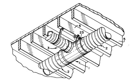
Figure 1 is a perspective view of flexible air ducts
connected to the tee-shaped fitting of the present invention
~ mounted on a floor;
Figure 2 is a perspective view of the tee-shaped
fitting secured to floor joists;
Figure 3 is an exploded, perspective view of the
tee-shaped fitting and cooperating support ring and collar;
Figure 4 is a fragmentary perspective view of one of
the keepers on the collar;
Figure S is a fragmentary perspective view of one of
the keepers on the support ring;
Figure 6 is an enlarged, sectional side elevational
view of the tee-shaped fitting having a support collar and
duct collar connected to each end thereof;
Figure 7 is a sectional, elevational view of a
reducer fitting of the present invention; and
Figure 8 is a sectional, elevational view of a wye-

shaped fitting of the present invention.

2104499

DESCRIPTION OF THE PREFERRED EMBODIMENTS
Referring to the drawings and more particularly toFigures 1 and 2, the fitting 1 of the present invention is
employed to connect conventional flexible air ducts 2 and 3
used in heating and air conditioning systems, the particular
illustrated fitting being a T-shaped fitting constructed and
arranged to be mounted on a floor 4 or secured to floor joists
5, whereby air ducts 2 can be used as a main trunk while the
smaller ducts 3 can be used as branch runs.
10 ~ The details of the construction of the T-shaped
fitting 1 are illustrated in Figures 3 and 6, wherein it will
be seen that the fitting comprises an inner tubular shell 6
and an outer tubular shell 7 having a layer of insulation 8
therebetween. The inner shell 6 includes a main integral
conduit having tapered portions 9, and a branch conduit 10
extending normal to and communicating with the main conduit.
The flexible air ducts 2 and 3 are connected to the
main and branch conduits by pulling the jacket 11 and
insulation 12 away from the core 13 and taping or banding the
core to the conduit as at 14. The insulation 12 and outer
jacket 11 are placed back over the insulation and core 13, and
the outer jacket 11 is taped or banded as at 15.
In order to dress the coupled end of the flexible
duct, a collar 16 is slidable over the end of the taped
flexible duct and is held in place by a retaining ring 17
having a plurality of circumferentially spaced, radially
outwardly extending keepers 18 cooperating with a plurality of
circumferentially spaced, correspondingly configured, radially


210~9~


inwardly extending keepers 19 provided on the end of the
collar 16.
The retaining ring 17 is rotatably mounted on the
inner tubular shell 6 and held thereon by a shoulder 20 formed
integral with the conduit portion 9. As will be seen in
Figures 1, 2 and 3, the retaining ring 17 is formed with a
flared base portion 21 having nail receiving apertures 22 for
securing the T-shaped fitting 1 to the floor 4, as shown in
Figure 1, and strap receiving openings 23 for securlng the T-

~ shaped fitting 1 to a floor joist 5, as shown in Figure 2. By
- rotatably mounting the retaining ring 17 on the inner tubular
shell 6, the retaining ring can be rotated so that the T-
shaped fitting 1 can be secured to or suspended from any
supporting surface positioned at various angles, depending
upon the desired direction of the branch conduit 10. To hold
the retaining ring 17 at the desired angular position, a
plurality of circumferentially spaced protuberances 24 are
formed on the inner face 17a of the ring 17 and cooperate with
similarly configured, circumferentially spaced recesses 25
formed in the outer face 7a of the outer tubular shell 7.
To complete the description of the T-shaped fitting
1, the portion 7b of the outer tubular shell surrounding the
branch conduit 10 is provided with a plurality of
circumferentially spaced, radially outwardly extending keepers
26 which would cooperate with the keepers on a collar similar
to that of collar 16, to thereby dress the end of a flexible
conduit which would be secured to the branch conduit 10.


2104499

While the description of the insulated fitting of
the present invention has been directed to the T-shaped
fitting 1 as shown in Figures 1 to 6, the salient features of
the T-shaped fitting can also be employed in other fittings
such as a reducer 27 illustrated in Figure 7 and a wye-shaped
fitting 28 shown in Figure 8. In each instance, the fittings
comprise an inner shell 27a, 28a, and outer shell 27b, 28b and
a layer of insulation 27c and 28c therebetween. The reducer
27 i-s provided with a tapered conduit 27d and the wye-shaped
~ fitting 28 is provided with tapered branch conduits 28d. The
end faces of the outer tubular shells 27b and 28b are provided
with the circumferentially spaced radially outwardly extending
keepers 27e and 28e adapted to receive keepers on a collar
similar to the collar 16 shown in Figures 3 and 6 to thereby
dress the ends of the flexible ducts which would be taped to
the tapered conduit 27d and 28d.
The opposite end faces of the outer tubular shells
27b and 28b are each provided with a radially inwardly
extending flange 27f and 28f forming a catch for coupling
another fitting thereto.
From the above description, it will be appreciated
by those skilled in the art that the insulated fittings of the
present invention provide an improved connection for the main
trunk and branch runs of insulated flexible air ducts. The
rotatably mounted retaining ring 17 being adjustable on the T-
shaped fitting so that the fitting can be mounted on flooring,
joists, or suspended at any desired angle. The collar 16
connected to the retaining ring 17 covers the secured end of


2104499
the flexible air ducts 2 and 3 to thereby provide a
professional appearance, the same being true of collars
connected to reducers and wye-shaped fitting having ducts
secured thereto.
It is to be understood that the form of invention
herewith shown and described is to be taken as a preferred
form of the invention, and that various changes in the shape,
size and arrangement of parts may be resorted to, without
departing from the spirit of the invention or scope of the
~ subjoined claims.

Representative Drawing
A single figure which represents the drawing illustrating the invention.
Administrative Status

For a clearer understanding of the status of the application/patent presented on this page, the site Disclaimer , as well as the definitions for Patent , Administrative Status , Maintenance Fee  and Payment History  should be consulted.

Administrative Status

Title Date
Forecasted Issue Date 1996-07-16
(22) Filed 1993-08-20
Examination Requested 1993-10-15
(41) Open to Public Inspection 1995-02-21
(45) Issued 1996-07-16
Deemed Expired 1998-08-20

Abandonment History

There is no abandonment history.

Payment History

Fee Type Anniversary Year Due Date Amount Paid Paid Date
Application Fee $0.00 1993-08-20
Maintenance Fee - Application - New Act 2 1995-08-21 $50.00 1995-08-16
Maintenance Fee - Patent - New Act 3 1996-08-20 $50.00 1996-08-19
Owners on Record

Note: Records showing the ownership history in alphabetical order.

Current Owners on Record
ROSZIN, JOSEPH M.
Past Owners on Record
None
Past Owners that do not appear in the "Owners on Record" listing will appear in other documentation within the application.
Documents

To view selected files, please enter reCAPTCHA code :


To view images, click a link in the Document Description column. To download the documents, select one or more checkboxes in the first column and then click the "Download Selected in PDF format (Zip Archive)" or the "Download Selected as Single PDF" button.

List of published and non-published patent-specific documents on the CPD .

If you have any difficulty accessing content, you can call the Client Service Centre at 1-866-997-1936 or send them an e-mail at CIPO Client Service Centre.


Document
Description 
Date
(yyyy-mm-dd) 
Number of pages   Size of Image (KB) 
Claims 1995-04-14 4 242
Description 1995-04-14 6 392
Abstract 1996-07-16 1 17
Claims 1996-07-16 4 134
Drawings 1996-07-16 4 146
Cover Page 1995-04-14 1 68
Abstract 1995-04-14 1 63
Description 1996-07-16 6 208
Cover Page 1996-07-16 1 12
Drawings 1995-04-14 4 422
Representative Drawing 1999-07-12 1 23
Office Letter 1994-03-23 1 70
PCT Correspondence 1996-05-10 1 51
Prosecution Correspondence 1993-10-15 1 48
Prosecution Correspondence 1994-04-19 1 41
Prosecution Correspondence 1993-12-15 1 36
Fees 1996-08-19 1 45
Fees 1996-09-09 2 46
Fees 1995-08-16 1 36