Note: Descriptions are shown in the official language in which they were submitted.
2 1 ~ 7
~ 1
MONITORING APPARATUS AND SYSTEM.
The present invention relates to an apparatus and system
for monitoring street lighting.
Devices that are designed to perform a task dependent on
the time or on environmental conditions are often cheaper
to operate and more reliable than manually operated
devices. An example of a device which benefits from
automation is the street lamp. It would be expensive to
employ a workforce so as to have each lamp turned on
manually as daylight faded and turned off again at
daybreak. There is, however, a disadvantage in having
automatic street lamps responsive to time and/or to
ambient lighting levels. The fallure of an automatic
street lamp may go undetected for a substantial time.
Strategies for preventing unknown failures from existing
for a long time may include the manual inspection of
street lights or maintenance being performed more
frequently than the expected lifetime of the constituent
parts of the street lamp would dictate. However, such
strategies are inefficient and/or expensive.
According to a first aspect of the invention, there is
provided an apparatus for monitoring operation of a
street light, comprising providing means for providing
data representing the operational state of the street
light, storing means for storing the data, and access
means for providing external access to the stored data.
The providing means may comprise a transducer for
monitoring the supply of electrical power to a lamp of
the street light.
The storing means may comprise means for storing the or
each time at which the street light is turned on or off.
2~Ln~7~
~ 2
The access means may comprise means for sending signals
via a power supply line to the street light.
According to a second aspect of the invention, there is
provided a system for monitoring operation of a plurality
of street lights, comprising an apparatus according to
the first aspect of the invention for each street light,
and a monitoring station comprising communication means
for communicating with the access means of each of the
apparatuses, storage means for storing data from the
access means, and external communication means for
providing external access to the data stored in the
storage means.
Preferably the monltoring station is located at a
junction of power supply lines to the street lights and
the communication means is arranged to communicate with
each of the access means via the power supply lines.
Preferably the communication means is arranged to
interrogate and receive data from each of the apparatuses
in turn.
Preferably the monitoring station includes processing
means ~or producing diagnostic data representing the
operative condition of each street light and for storing
the diagnostic data in the storage means.
Preferably the external communication means includes data
transmitting means responsive to an external enquiry for
transmitting at least some of the data stored in the
storage means. The data transmitting means may be
arranged to respond to an enquiry and transmit data by
means of a line such as a power supply or telephone line,
radio communication, ultrasonic communication, or in any
other suitable way.
2 ~
~ 3
The system may comprise a plurality of monitoring
stations, each arranged to serve a respective group of
street lights. The system may further comprise a mobile
interrogating station arranged to lnterrogate each
monitoring station when in the vicinity thereof.
It is thus possible to provide an apparatus and a system
which permits the operation of a street lighting
installation to be improved and/or the requirement for
servicing personnel to be reduced.
The invention will be further described, by way of
example, with reference to the accompanying drawings, in
which:
Figure 1 is a schematic diagram of an arrangement of
street lamps;
Figure 2 is a schematic diagram of an arrangement of
street lamps incorporating an embodiment of the present
invention;
Figure 3 is a block diagram of a basic signalling module
of the embodiment of Figure 2;
Figure 4 is a block diagram of a logger unit of the
embodiment of Figure 2;
Figure 5 is a flow diagram illustrating operation of the
basic signalling module of Figure 3; and
Figure 6 is a flow diagram illustrating operation of the
logger unit of Figure 4.
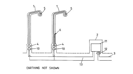
Figure 1 shows a street lamp installation in which, for
convenience, only two street lamps and only one supply
box 2 are shown. However, any number of such lamps may
210~797
be connected to in groups to any number of such supply
boxes 2. The street lamps of the group shown have a
single node of electrical connection with the mains power
supply 3 at the supply box 2. Each street lamp 1 has a
controller 4 that controls the power to a lamp 5 so as to
switch it on and off at predetermined times, and/or in
response to the ambient lighting condition as measured by
a light sensor 6.
Figure 2 shows an installation in which a basic
signalling module (BSM) 10 is located in each street lamp
1. Each BSM 10 is arranged to monitor the current taken
by the associated lamp 5 and to communicate with a logger
11 at the supply box 2 via power cables 13. A filter 12
is provided in the supply to the street lamp/BSM/logger
combination so as to prevent mains borne communication
signals from entering the mains supply and interfering
with other equipment. Each BSM 10 continuously monitors
the operation of its associated street lamp.
Each BSM 10 is microprocessor controlled, the
microprocessor interpreting the data about the associated
lamp 5 in order to determine if the associated lamp 5 is
working correctly. The microprocessor also handles the
communications between each BSM 10 and the logger 11.
Each sSM 10 has a unique address and will not respond
until it has been addressed by the logger 11 and invited
to respond.
The logger 11, which is also microprocessor controlled,
periodically addresses each BSM 10 and receives data from
it. The data are stored in the logger along with the
lamp address so that the performance of each individual
street lamp 1 can be identified. The logger 11 contains
a non-volatile memory so that stored data will not be
affected by power loss.
2101797
~ 5
The logger 11 stores the street lamp status in
conjunction with the time so that the action of street
lamps 1 controlled by timers or light sensitive elements
may be monitored. If no current is sensed for a specific
lamp 5 in a 24 hour period, the logger records that the
specific lamp 5 has failed. If a group of electrically
adjacent BSMs 10 fails to respond, a fauit in the power
cables 13 is the probable cause. The approximate
position of such a fault may be found by e~min~tion of
the data recorded by the logger 11. If a specific BSM 10
fails to respond, the logger 11 records that the specific
BSM 10 has failed. The logger 11 can also maintain data
such as the total hours each lamp 5 has been lit, the
number of hours that have elapsed since a lamp 5 has
failed, the number of hours that have elapsed since a
lamp was tested, and the BSM number and lamp post serial
number associated with each street lamp 1.
Periodically the logger is interrogated by a data
collection unit so as to collect the data from a
plurality of loggers 11 for analysis. The transfer of
data from each logger 11 to the data collection unit
could be done by electrical connection to a socket on the
logger 11, or an ultrasonic or radio link, so that the
data collection unit need only be in the proximity of a
logger 11, or a supply box 2 housing a logger 11, to
collect data. Alternatively the data could be collected
via a telephone link. The telephone link could be either
a land line or a radio telephone.
The data collection unit (not shown) processes data from
the loggers and may include a display for providing an
indication of faulty street lamps 1 or faulty BSMs 10.
The data collection unit can also be used to program a
logger 11 so that extra street lamps 1 can be added to an
existing installation or the address of a BSM 10 can be
updated if a faulty BSM 10 is replaced. Once the
- 210~97
~ 6
re~uired data have been passed between the logger 11 and
the data collection unit, the logger 11 is re-
initialised.
Figure 3 shows a block diagram of a BS~ 10. Each BSM 10
receives its power from, and commllnicates to the logger
11 by, the power cables 13. A power supply 14 provides
power to a microcontroller ~5. The current through the
associated lamp 5 is measured by a current sensor 16.
The measured value of the current is converted to digital
data by an analogue to digital converter 17 and supplied
to the microcontroller 15. The microcontroller 15
communicates with the logger 11 via a signal driver 18
that allows the communication signals to be passed along
the power cables 13.
As shown in Figure 4, the logger 11 includes a
microprocessor 20. The microprocessor 20 receives power
from a power supply 21 connected to the power cables 13.
The microprocessor 20 has a program read only memory 21
and a random access memory 22. Processed data are stored
in a non-volatile memory 23 provided by an electrically
erasable read only memory. The microprocessor
communicates with each BSM 11 via a signal driver 24
connected to the power cables 13.
The microprocessor has communications drivers 25 for
communication with external devices. The drivers 25 may
be linked to an external device such as a data collection
unit by a direct electrical connection, or by telephone,
radio or ultrasonic link.
Figure 5 shows a flow chart for the operation of each BSM
10. After initialisation at step 30, each BSM 10 checks
the status of its associated street lamp 1 at step 31 by
measuring the associated lamp current and stores it at
step 32. At step 33 the BSM 10 checks the power cables
2104797
_ 7
13 to determine whether the logger 11 is calling. If the
logger 11 is not calling, then control returns to the
step 31. If the logger 11 has sent a call signal, the
BSM performs steps 34 to 36 to check if it is being
polled and, if the logger 11 is ready to receive data.
If the BSM 10 is selected and the logger 11 is ready,
then the BSM 10 transmits its data to the logger 11 at
step 37. After transmission, if the BSM 10 is not being
polled, or communication between the BSM 10 and the
logger 11 has failed, control is returned to the step 31.
Figure 6 shows a flow chart for the logger 11. After
initialisation at step 40, the logger 11 starts
collecting data from each BSM 10 on its network. Step 41
selects the first BSM 10. At step 42 the addressing and
data request signals are issued and at step 43 the
response of the BSM 10 is stored. Step 45 checks to see
if an external device, such as a data collection unit,
wishes to communicate with the logger 11. If no external
device wishes to communicate control is passed to step
46. Step 46 checks to see if all the BSMs on the network
have been polled. If not, step 47 selects the next BSM
and control is then passed to the step 43. Once all the
BSMs 10 have been polled, control passes back to the step
41.
If an external device does wish to communicate, the
logger 11 identifies itself at step 48. At step 49 the
logger checks whether the caller wishes to receive data
from the logger 11. If so, the logger 11 sends its data
at step 52 and then checks, at step 53, if the caller
requires the data to be resent. Once the data have been
successfully passed, operation of the logger 11 returns
to the step 40. If the caller does not wish to receive
data, control passes to step 50. The logger 11 checks
whether the caller wishes to transmit data. For
instance, the number of street lamps 1 on the network may
210~79~
_ 8
have been changed requiring the logger operation to be
modified. If the caller wishes to transmit data, then
the logger 11 receives the data at step 51 and then
returns control to the step 40. If the caller fails to
indicate that it wishes to transmit data, then the logger
11 returns to monitoring of the BSMs 10 at the step 46.
After data from one or more loggers 11 have been
collected by one or more data collection units, the data
may be loaded into a computer for analysis. The analysis
may show when a street lamp 1 has not been on at all,
when a street lamp 1 has failed to extinguish, when a
street lamp 1 has illuminated outside a given time period
or when a group of street lamps 1 has failed. Such
analysis may indicate lamp failure, light sensor failure,
timer failure and power cable faults respectively. The
computer may produce a list of faulty street lamps 1 and
suggest the most likely fault, the street lamp location,
parts required, likely repair time and when the fault
occurred. Statistical data about street lamp failure
rates may also be produced.
It is thus possible to provide an automatic checking
system which does not require manual checking of
individual street lights for correct operation. Faults
can be detected and diagnosed more quickly so as to
permit more rapid repairs. The cost of manufacturing,
installing, and operating such system can be rapidly
recovered by the reduced personnel requirements which the
system permits, and the efficiency of street lighting can
be substantially improved.
Various modifications may be made within the scope of the
invention. For instance the BSMs 10 may be arranged to
participate in the control of the street lamps 1 such
that, at certain times such as dusk, only a proportion of
the street lamps are on. For this purpose, the BSMs 10
~ ~4~
~ g
,. .
may be arranged to receive, as well as send, data. Thus,
the street lamps may be arranged as two or more groups
which are progressively illuminated as light levels fall.
A substantial saving in electricity may be obtained by
such a system.