Note: Descriptions are shown in the official language in which they were submitted.
210~84~
LONG HOLE CHEMICAL GROUT INJECTOR SYSTEM
BACKGROUND OF THE INVENTION
Field of the Invention
The present invention, in general, relates
to a system for injecting grout into eracks that
require sealing via access holes and, more
partieularly, to apparatus that reeeive
ehemieally reaetive grout eomponents separately,
eombine the eomponents within the aeeess holes
near the eraek, and then, injeet the resultant
grout into the erack.
It is necessary to inject grout to seal
eraeks and erevices which occasionally develop in
a variety of structures. For example concrete
dams may settle and crack, sometimes leaking
water through the craeks that develop. Similarly
eraeks oeeasionally form in other types of
struetures sueh as tunnels, pipes, eonduits, and
sewer lines, for example. These eraeks may be
either above or below grade level.
A variety of reasons eontribute to eraek
formation ineluding settling of the strueture,
earthquake, aecident, and other causes. In some
eases, as hereinbefore mentioned, the eraeks will
leak water or other types of fluids therein and
will therefore require timely repair. A eraek or
erevice through which there is a leakage of fluid
is referred to as having a "pervasive flow"
occurring therein. In other cases a leakage does
not occur, yet the crack must nevertheless be
repaired to prevent further deterioration of the
strueture from occurring.
- 21018~
Occasionally the cracks afford easy access
and grout application is a task that is easily
accomplished. Often though the cracks are
difficult to access and require drilling long
holes and injecting grout through the drilled
holes.
The term "long hole" is used in favor of the
term "deep hole" because sometimes the holes that
are drilled in order to provide access to the
cracks and crevices are indeed long, but not
necessarily "deep" nor are the bored holes always
in a direction that extends below the drilling
equipment. It is necessary to drill at a variety
of angles with respect to the drilling surface
including drilling horizontally, down at some
predetermined angle, or even in an upwards
direction in order to access the crack that has
formed. These types of drilled holes are often
long but are not necessarily deep.
The difficulty with injecting grout into
long holes is due simply to the fast reacting,
and therefore also, the generally fast setting
nature that is required of the two part (binary)
chemical grouts that are, at present, commonly
used for such purposes.
The most common of the binary chemical
grouts that are used fall into one of the two
general classifications of grouts, either
monomers or polymers. Examples of monomer based
grouts include the acrylamides, acrylates, and
acrylics. A common example of a polymer grout is
polyurethane. The polyurethanes are often
referred to as simply the "urethanes" and include
many of the preferred types of grouts that are
used. Other types of binary chemical grouts not
- 2~0~
listed herein are sometimes appropriate for
certain types of repair.
There are many "systems" for each of these
grout families, each system usually referring to
some particular characteristic of the cured
grout. Examples of some systems include "gel",
"flexible foam", "hard foam", and "solid"
systems.
Certain repair situations respond better
when certain types of grout systems are used. For
example a solid grout system may be suitable for
use to effect repairs when no further motion by
the structure is anticipated. If continued motion
by the structure is anticipated to occur, then
repair may best be accomplished by the use of a
gel or perhaps a flexible foam grout system.
Regardless of the grout system selected, all
of the binary grouts are broadly defined to be
any two part material that can be made to flow,
usually by means of a pump, before the grout h~as
had time to set or to cure. The terms "set" and
"cure" are used interchangeably.
Each binary chemical grout formulation has
one principle component part that is referred to
as the "resin" and a second principle component
part that is referred to as the "catalyst". The
catalyst that is used for many of the preferred
grouts is water (H20). For certain binary grouts
other chemicals may be combined with either the
resin or the catalyst just prior to use. These
chemicals are referred to as "additives" and they
are used to modify some characteristic of the
grout being used. For example certain additives
are used to either lengthen or shorten the
"setting" time of a grout.
210 l~4~
For all types of binary chemical grouts when
the catalyst component is blended with the resin
component, a chemical reaction immediately begins
to occur whereby a grout is formed. The process
of blending the catalyst with the resin is often
referred to as "reacting" the components. For
many of the chemical grouts listed, a durable and
expansive fast setting grout is thereby formed
that is well suited for sealing these types of
cracks and crevices.
Furthermore, it is not a practical option to
attempt to slow reactant times while still
preserving the fast setting time that is
required. A slow reactant time (which would
provide a longer time to set) is especially ill
suited when injecting grout into formations
having a pervasive flow occurring therein. The
flow would tend to carry a slow reactant grout
away before it had sufficient time to set and to
adhere to its surroundings, thereby preventing an
effective sealing of the crack from occurring.
This type of situation is often encountered when
sealing cracks that occur in water dam
structures, for example.
It is also the case where "freezing sand" is
a requirement. Freezing sand is an expression
which originates from an industry practice
whereby coolant is used literally to freeze
sediments in position thereby permitting the
accomplishment of some other task which requires
a rigid formation. It is also currently used in
industry to refer, generally, to the
immobilization of sediments. In particular as
used hereinbelow, freezing sand refers to the
immobilization of sand, silt, and other sediments
' - 2 1 0 ~
in position by means other than by merely a
lowering of the temperature thereof.
Occasionally water dams and other structures
develop a flow, usually by water, that is
occurring underneath a portion of the reinforced
dam structure or foundation. The reinforced
portion of the dam structure may be constructed
of concrete or of other materials. In this
instance, water finds a path whereby it begins to
flow underneath the reinforced portion of the
structure. As the water flows it is constantly
eroding more of the sand, silt, and other
materials away from underneath the structure
which in turn is enlarging the pathway under the
structure, increasing the water flow rate,
weakening the supporting base, and for as long as
it continues, ever worsening and compounding the
problem.
The necessary repair procedure in such a
situation is to "freeze the sands" underneath the
structure and it is in general quite similar to
the required procedure for long hole crack repair
having a pervasive flow occurring therein. A two
part fast setting grout is reacted and is then
injected onto the sand, silt, and other materials
that are located underneath the reinforced
portion of the structure where the leak is
occurring thereby intersecting the flow of water.
The fast setting grout mingles with the sand and
silt and other materials and solidifies these
materials into a unitized mass together with the
grout.
A fortified and reinforced means of sealing
the leak and also of preventing further erosion
from occurring is thereby achieved. The result of
2 i O ~
this process is to "freeze the sands" that are
located underneath the structure. A slow setting
grout would in this instance also be removed and
carried away by the pervasive flow before it had
sufficient time to adhere to the sands and silt,
thereby once again preventing an effective repair
from occurring.
The hereinbefore described repair situations
require that the preferred two part grout
formulations, of necessity, have a short setting
time. However if a grout formulation having a
short setting time is reacted (mixed) at or near
the drilling surface and is then piped through
long holes to reach either a crack in the
structure or a leak that is located underneath
the structure, it will actually begin setting
prior to reaching the repair area.
Consequently after the grout begins to set,
its viscosity increases greatly so that it will
no longer flow easily through the conduit that is
used to transport the grout nor will it flow
properly into the cracks and crevices that
require sealing. Furthermore, once it begins to
set it will no longer be capable of achieving an
optimum bond with the materials surrounding the
crack or the crevice. After a reacted grout
begins to set, its efficacy at sealing cracks and
crevices or of "freezing sand" is greatly
diminished.
While a two part urethane grout is described
as one of the presently preferred grout
formations, other present and future grout
formulations will also have to be fast setting
for the same reasons as described hereinbefore.
It does not matter if the grout formulation
2113i~
requires the mixing together of two or more
component parts, to be effective at freezing sand
and at sealing cracks in the presence of a
pervasive flow, the grout, after having been
reacted, must be fast setting. Any fast setting
grout will in turn be difficult to pump through
long holes and will also experience diminished
repair efficacy if it is reacted too early prior
to injection into the crack or onto the sands and
silt to be frozen.
Accordingly, there exists today a need for a
long hole chemical grout injector system that is
able to react the grout components in ideal
proximity with respect to the crack that is being
sealed or with respect to the sands and silts to
be frozen. Clearly, an apparatus which allows for
the reacting of grout constituents at a close and
predetermined location with respect to the crack
or crevice requiring repair is a useful and
desirable device.
Description of Prior Art
Chemical grout injectors that are placed
within long holes at a predetermined location
away from a crack or crevice where they are used
for the mixing (reacting) of grout constituents
prior to injection of the grout into the crack or
crevice are not hereinbefore known. Means for
reacting grout at the surface of a long hole and
thereafter pumping the mixture into a crack or
crevice are known.
Means of pumping grout components separately
into a long hole through an inner and an outer
pair of grout pipes arranged in a coaxial manner
and into a mixing chamber that is located at the
210g8~
end thereof are known. The use of coaxial grout
pipes and a mixing chamber does not, however,
ensure the complete reacting together of grout
components, especially in the presence of a
pervasive flow. Coaxial grout pipes also tend to
be difficult to extract from a long hole
following usage.
While the structural arrangements of other
grout injection devices may, at first appearance,
have similarities with the present invention,
they differ in material respects. These
differences, which will be described in more
detail hereinafter, are essential for the
effective use of the invention and which admit of
the advantages that are not available with the
prior devices.
SUMMARY O F THE I NVENT I ON
It is an important object of the present
invention to provide a chemical grout injector
system that is particularly well suited to the
injection of all types of fast reacting binary
grouts into deep holes when there is a need to
control the time interval after having reacted
the grout constituents together until the time
when the reacted grout is injected into the area
requiring sealing.
Another object of the invention to provide a
chemical grout injector apparatus that is capable
of maintaining grout components separate from
each other until the components reach an optimal
distance away from the crack or crevice requiring
repair and to react the components together at
that ideal location.
- 210484q
Still another object of the invention to
provide a chemical grout injector apparatus
capable of automatically and adequately reacting
grout components together at a predetermined
location with respect to a crack or crevice.
Yet another object of the invention is to
provide a chemical grout injector apparatus which
discharges the reacted grout therefrom and into
the crack or crevice to be sealed or onto the
sand or silt to be frozen.
Briefly, a long hole chemical grout injector
system for use in the mixing of binary grout
components together and thereafter injecting the
resultant reacted grout into a crack or crevice
that is constructed in accordance with the
principles of the present invention has an
injector apparatus that is of a shape and size
suitable for insertion into a bored hole, and has
a means for securing the long hole chemical grout
injector apparatus in position within the bored
hole during grout injection, a means for separa-
tely receiving grout components that are pumped
therein, a means for maintaining the separation
of components passing through a portion of the
grout injector apparatus, a means for combining
and thoroughly mixing (reacting) the grout
components together, a means for discharging the
reacted grout therefrom, and a means for
releasing and thereby retrieving the long hole
chemical grout injector apparatus from the bored
hole.
- 21 04844
9a
In a preferred embodiment the invention is
directed to a chemical grout injection system for
sealing a crack in a structure, access to said
crack being provided by at least one hole formed
in said structure, said system comprising pipe
means in sections of predetermined lengths and
including means for assembling at least two of
said sections together to form a lining for said
hole to a predetermined depth; path defining
means for forming at least two chemically
separate paths within said pipe means; valve
means attached to each of said chemically
separate paths at said predetermined depth;
means for inserting said path defining means into
said lining; means for securing said path
defining means at a predetermined location in
said lining; and means for removing said path
defining means from said lining; whereby grout is
formed from at least two chemically reactive
components as they combine at said predetermined
depth for filling said crack.
A-
-
2 1 ~ ~ c~
BRIEF DESCRIPTION OF THE DRAWINGS
FIG. 1 is a cross sectional view of a
portion of a structure in need of crack repair
having a preferred form of chemical grout
injector apparatus inserted into proper position
within a bored hole prior to the injection of
grout.
FIG. 2 is cross sectional view of the
injector apparatus only when taken on the line 2-
2 in FIG 1.
FIG. 3 is a cross sectional view of a fifthcoupling component only of the injector apparatus
taken along the line 3-3 in FIG 2.
FIG. 4 is an end view of the fifth coupling
component of the injector apparatus.
FIG. 5 is a cross sectional view of a
portion of the valve assembly component of the
injector apparatus.
DETAILED DESCRIPTION OF THE INVENTION
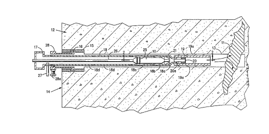
Referring to FIG. 1 is shown a long hole
chemical grout injector apparatus identified, in
general, by the numeral 10. Details relating to
the construction of the injector 10 are included
hereinafter. The injector 10 is shown in relation
to a crack 11 that is in need of sealing which
has formed in a structure 12.
For the purpose of this discussion the
structure 12 is assumed to be a concrete water
210 4~ i
11
dam and water (not shown) is assumed to be
flowing through the crack 11.
A long hole 13 of suitable diameter and
length has been bored into the wall 14 of the dam
structure 12 so as to intersect and pass through
the crack 11. The long hole 13 is bored through
the dam structure 12 at the required angle so as
to reach the crack 11 and may typically require
drilling through rock, cement, and other
materials by the use of a core-type diamond drill
boring apparatus (not shown).
The access area that is provided in most dam
structures 12 is referred to as the gallery area
(not shown). The gallery is a narrow corridor,
much like a tunnel, which runs along the length
of the water dam structure 12. Therefore the wall
14 (shown) is one of the two gallery walls (other
wall not shown). The long hole 13 is bored
starting from the one gallery wall 14 providing
that the gallery affords the best access to the
crack 11. Otherwise the long hole 13 is bored
starting from an exterior location of the
structure 12 that affords the best access to the
crack 11.
While only one such long hole 13 is shown,
actual repair of the crack 11 often requires the
drilling of many such long holes 13, each of
which intersects, and thereby provides access to,
a portion of the crack 11. The injector 10, as
hereinafter described, is used in each of the
long holes 13 that is bored to supply an adequate
amount of grout to completely fill the expanse of
the crack 11.
The long hole 13 is considered to be "long"
if the grout formulation that is used to seal the
210~841
12
crack 11 would begin to set enough to increase
its viscosity during pumping prior to reaching
the crack 11 if the grout components were to be
reacted (mixed together) at or near either the
gallery wall 14 or "collar" area (not shown).
The area where either drilling of the long hole
13 or pumping of the grout originates, whether in
the gallery or on the surface of the structure
12, is referred to as the "collar" area.
Whenever a fast setting grout is used even a
very short hole 13 is considered "long" if it can
benefit from the use of the injector 10.
Hereinafter whenever reference is made to a "hole
13" it is assumed to be long enough so as to
derive benefit from the use of the chemical grout
injector 10 apparatus for the sealing of cracks
11. Reference to a "hole 13" and to a "long hole
13" are used interchangeably throughout the
specification.
Core samples (not shown) are periodically
extracted during the drilling process, and it is
by a monitoring of the removed core samples that
a verification of the intersection of the hole 13
with respect to the crack 11 is confirmed. This
is accomplished both by noting a discoloration of
the core sample in the vicinity of the crack 11
as well as by a study of the actual core sample
materials that are extracted and sometimes by
noting the presence of contaminants (not shown)
that have migrated into the crack 11 as a result
of any pervasive flow which may be occurring
therein. If a pervasive flow is not occurring,
confirmation may involve a more careful study
noting fractures and possible voids in the
extracted core samples.
21~4~4~
To facilitate crack 11 repair it is
necessary to add cement grout reinforcement 15 to
an enlarged portion of the hole 13 that is formed
immediately upon penetration into the gallery
wall 14. The cement grout reinforcement 15 is
used to provide an anchor location for affixing a
pipe coupling 16 that is cemented directly to the
structure 12.
The pipe coupling 16, in turn, is useful for
securing and maintaining the drilling apparatus
(not shown) in proper alignment during subsequent
boring of the hole 13, and later for securing a
packing gland 17 and a packer pipe 18 in the
desired position. The packing gland 17 and packer
pipe 18 are described in greater detail
hereinafter.
Referring also to FIG. 2, the packer pipe 18
is comprised of three threaded specially modified
sections 18a, 18b, 18c and a plurality of as many
as is required threaded standard sections 18d
that are assembled together in specific order and
are then inserted, section by section, into the
hole 13.
Certain modified sections 18a, 18b, 18c, of
the packer pipe 18 are fabricated so as to
cooperate with the injector lo. Details of
construction of the modified sections 18a, 18b,
18c are included hereinafter.
After having bored the hole 13 and after
having affixed the pipe coupling 16 thereto, the
next step in the process of deep hole 13 crack 11
repair is to first properly prepare and to then
insert the modified sections 18a, 18b, 18c and
the remaining standard sections 18d of the packer
pipe 18 into the hole 13. Preparation begins with
21 0~844
14
the first section 18a of the packer pipe 18 and
requires the assembly together of a cup packer 19
and of a resident rod 20.
The resident rod 20 is attached by threads
(not shown) to the inside of the cup packer 19.
The cup packer 19 having the resident rod 20
attached therein is attached to the end threads
18f of the first section 18a of the packer pipe
18.
Construction of the cup packer 19 includes a
plurality of circular packer seals l9a about its
periphery to prevent any water that may be
flowing in the crack 11 from otherwise passing
beyond the cup packer 19, around the outside of
the packer pipe 18, and flowing in the space
between the outside diameter of the packer pipe
18 and the inside diameter of the hole 13.
The packer seals l9a are typically
constructed of either rubber, neoprene, leather,
or some other type of pliable material. The
inside of the cup packer 19 is open to allow for
the reacted grout, as is described hereinafter,
to flow out from the end of the cup packer 19 and
into the crack 11.
The resident rod 20 is a known method of
mixing substances together that relies upon
inducing a motion by the substances that are
forced to pass therein which, consequently,
agitates and blends the substances together. The
use of a resident rod 20 to react grout
components together in a long hole 13 is not
hereinbefore known.
Inside the resident rod 20 are angle clips
20a that are affixed firmly in position within
the resident rod 20. The angle clips 20a cause
21~1~4~
the materials being forced therein to swirl
around as they pass through the resident rod 20
and, therefore, to mix thoroughly together. The
resident rod 20 thereby improves the efficacy by
which the resin and the catalyst are reacted.
The first section 18a has a lip 18e area
which serves to limit on the one side the
allowable travel of a valve assembly 21. The
valve assembly 21 is inserted as shown into the
first section 18a before the second section 18b
is threaded onto the first section 18a.
The second section 18b of packer pipe 18 is
fastened onto the first section 18a by tightening
the threads 18j of the second section 18b onto
the corresponding first section threads 18k
thereby securing the valve assembly 21 in
position therein.
The threads 18j of the second section 18b
bear upon the valve assembly 21 and force the
valve assembly 21 in turn to bear tightly against
the lip 18e. As such the valve assembly 21 forms
a seal to prevent any fluid (water or resin) from
flowing, in either direction, through the space
between the lip 18e and the valve assembly 21.
The end threads 18h of the third section 18c
are then used to secure the third section 18c to
corresponding threads (not enumerated) of the
second section 18b.
The sub-assembly of packer pipe 18 now
consists of the first section 18a having with the
cup packer 19 attached thereto and the resident
rod 20 located therein at one end thereof, and at
the remaining end thereof, having the valve
assembly 21 located therein between the first
section 18a and the second section 18b and also
- 2~0~8~ l
16
having the third section 18c attached to the
second section 18b. The sub-assembly is inserted
into the hole 13 beginning first with the cup
packer 19.
The second section 18b contains a locking
area 18g that consists of a thinner inside
diameter portion that is formed near to where the
second section 18b is threaded onto the third
section 18c. The locking area 18g of the second
section 18b provides an area whereby the locking
dogs 22 of the injector 10 are able to expand
under leaf spring 23 tension, as shall be
hereinafter described in greater detail, and to
rest upon the end threads 18h of the third
section 18c.
The locking dogs 22 thereby serve to secure
the injector 10 in place within the packer pipe
18 during grout application. The distance the
locking area 18g is located from the lip 18e is
controlled to ensure that when the injector 10 is
fully inserted into the packer pipe 18, the
locking dogs 22 will be in the proper position to
expand into the locking area 18g.
The third section 18c of the packer pipe 18
contains a water by-pass 24 area consisting of a
thinner inside diameter near to where the third
section 18c is threaded onto a standard section
18d that is similar in construction to the
locking area 18g of the second section 18b. The
purpose of the water by-pass 24 is to allow water
to flow past the pump-in glands 25 and around the
body of the injector 10.
The distance that the water by-pass 24 is
located from the lip 18e of the packer pipe 18 is
set to ensure that the length of the injector 10
21D4~
17
and the valve assembly 21, when combined, will
result in the pump-in glands 25 of the injector
10 resting in the area afforded by the water by-
pass 24 when the injector 10 is fully inserted
into the packer pipe 18.
The injector 10, when it is later inserted
into the fully assembled packer pipe 18 behind
the valve assembly 21, is thus permitted to
travel within the packer pipe 18 only until it
contacts the valve assembly 21. Additional detail
regarding the insertion of the injector 10 into
the packer pipe 18 is included hereinafter.
A standard section 18d is threaded onto the
third section 18c and is thereafter inserted into
the hole 13. As many standard sections 18d are
used as is required. The number of standard
threaded sections 18d that are used is determined
by the length of the hole 13 and by the desired
placement of the injector 10 with respect to the
crack 11. The overall length of each standard
section 18d that is used may vary providing each
standard section 18d is able to thread onto
either the third section 18c or onto other
standard sections 18d.
The length chosen for each of the three
modified sections 18a, 18b, 18c is set to
correspond properly with the length of the
injector 10 and the valve assembly 21, and cannot
be altered without making similar changes to the
dimensions of either the injector 10 or valve
assembly 21. Therefore in order to control
precisely the overall length of the packer pipe
18, the length of each standard section 18d as
well as the number of standard sections 18d that
are used are varied accordingly.
104~4
18
Additional standard sections 18d are added,
one by one, and inserted into the hole 13 until
the overall length of packer pipe 18 that is
desired has been obtained. The outside diameter
of all modified sections 18a, 18b, 18c, and of
the standard sections 18d of the packer pipe 18
must, of necessity, be somewhat less than the
inside diameter of the bored hole 13.
The overall length that is chosen for the
packer pipe 18 is selected to terminate with the
cup packer 19 being situated a predetermined
distance away from the actual crack 11. The
bored hole 13, as shown, will normally proceed a
short distance beyond the actual crack 11 and
will then terminate at the point where drilling
had stopped and the last core sample had been
extracted.
The final position that is selected for the
placement of the first section 18a of the packer
pipe 18 within the hole 13, and therefore also
for the injector 10, cup packer 19, and resident
rod 20, is a repair specific variable that
depends upon a variety of factors. In general,
the distance that is selected for the injector 10
to be placed from the crack 11 during grout
application is governed by the amount of time
that the grout will have to set prior to reaching
the crack 11.
Both the reactant and setting times of the
grout formulation are determinant factors which
are used to establish the placement of the
injector 10, as are the pervasive flow rates
which may be occurring through the crack 11. The
size of the crack 11, and the materials
surrounding the crack 11 to which the grout must
-- 210~8~ 1
19
adhere to, are also influential factors as is the
speed at which the grout components are being
pumped into the hole 13.
In certain instances the cup packer 19 is
placed only inches away from the crack 11 while
in other specific instances it is located many
feet away from the crack 11. The design of
injector 10 allows for the functional placement
of the injector 10 anywhere within the length of
the hole 13. The depth within the hole 13 to
which the first section 18a is inserted limits
the depth to which the injector 10 may later be
inserted as well. Grout discharge, which occurs
at the end of the cup packer 19, can be set to
occur directly adjacent to the crack 11 or from a
location that is considerably closer to the
collar area.
In this manner the injector 10 is suitable
for use over a very wide range of crack 11 repair
situations and with a wide variety of two-part
(binary) grouts having various reactant and
setting times while also being able to take into
account the many other application specific
requirements that warrant consideration.
After the entire packer pipe 18 has been
fully assembled, section by section, and has been
pushed into the hole 13 so that the first section
18a has reached the desired location (depth)
within the hole 13, then the packer pipe 18 is
secured in position by the pipe coupling 16 and
by other component parts of the injector 10
system that are attached to the pipe coupling 16
and are described hereinafter.
After the fully assembled packer pipe 18 has
been inserted into the hole 13 to the depth
- 210~8~
desired for grout application, the packer pipe
18 is maintained in position by affixing the
packer pipe 18 securely to a packer pipe clamp 28
that is attached to the pipe coupling 16.
The packer pipe clamp 28 is attached to the
pipe coupling 16 and is used to secure the
packing gland 17 and the packer pipe 18 to the
pipe coupling 16 thereby maintaining the assembly
in a static position with respect to the dam
structure 12. Attached to the packer pipe clamp
28 are one or more threaded bolts 28a which
engage corresponding threads (not shown) within
the packer pipe clamp 28 and, when tightened,
pass through clearance holes (not shown) that are
provided for each bolt 28a in the packer pipe
clamp 28 until each bolt 28a bears upon the
packer pipe 18 that is located therein, thus
securing it in position. The packer pipe clamp 28
is also sometimes referred to as a "spider
clamp".
The injector 10 is inserted next into the
assembled packer pipe 18 from the collar area.
The injector 10 is connected to a urethane
injection hose 26 that first passes through the
center of the packing gland 17 and is then
secured to a nipple (not shown) that is attached
to nipple threads 29 located at one end of the
injector 10.
At this point, the injector 10 is located
inside the packer pipe 18 near the collar area.
Details as to how the injector 10 is moved from
the collar area to the end of the packer pipe 18
near the crack 11 are included hereinafter.
The packing gland 17 is attached next to the
end of the packer pipe 18 by pipe threads (not
2104~
shown) or by other attachment methods as are
known and appropriate.
The urethane injection hose 26 is a type of
conduit that is used generally to convey the
resin component of the chemical binary grout
formulation that is to be pumped (later) under
pressure to the injector 10. The urethane
injection hose 26 is typically constructed of a
strong and flexible polyvinylchloride (PVC)
material, although other pipe materials are used
as well. The advantage to the use of PVC is that
it is flexible, relatively inexpensive,
continuous, and strong.
The packing gland 17 is used to permit the
pumping of fluids into the packer pipe 18 while
maintaining separation of the fluids, each from
the other. For use with a polyurethane grout,
urethane resin is normally pumped into the
urethane injection hose 26 and water (the
catalyst) is pumped into the water inlet port 27.
The water (not shown) that is pumped into the
inlet port 27 flows in a coaxial path around the
urethane injection hose 26 and bears upon the
pump-in glands 25 of the injector 10.
For use with other types of binary (two
part) grouts, each of the other grout components
would be pumped separately, one into the urethane
injection hose 26 and the other component into
the water inlet port 27 accordingly.
If a grout requiring the mixing of three or
more component parts together is used, the
present injector 10 system is equally viable
without modification providing the components may
be combined at the collar area in some non-
reactive fashion so as to reduce the materials to
2~0~84~
22
be pumped to the injector 10 to two formulations
whereby one formulation is pumped into the
urethane injection hose 26 and the other
formulation is pumped into the water inlet port
27. Either formulation may contain the resin or
the catalyst as well as any additives that are
used, providing the two formulations are
maintained separate from each other until they
reach, and are combined by, the valve assembly 21
of the injector 10.
If a three part (tertiary) grout formulation
is used which does not permit combining any of
the components together until just prior to a
full and complete blending together (reacting) of
all grout components, then the injector 10 system
is modified accordingly as would be obvious to
those now skilled in the art.
For example, one such modification would be
to use an additional injection hose (not shown)
passing through a modified packing gland (not
shown) in addition to the urethane injection hose
26. Both injection hoses would connect together
at a "Y" shaped adapter (not shown) attached to
the nipple (not shown) of the injector 10 whereby
two of the grout components would be combined
together upon entry into the "Y" adapter of the
injector 10, a moment before the third component
part is combined (reacted) with the other two
combined components by the valve assembly 21 of
the injector 10.
Other similar types of modifications made to
the injector 10 as are made necessary for use
with certain specialized grout formulations are
thereby anticipated. For example, if a grout
formulation requiring four or more component
21~48~4
parts to be maintained separately is used,
additional urethane injection hoses (not shown)
are routed to pass through a specially modified
packing gland (not shown) and are connected to
additional "Y" shaped adapters (not shown) that
are located near the injector 10. As such the
beneficial use of the injector 10 with a wide
variety of present and future types of chemical
grouts and additives is assured.
The water (or other type of catalyst) that
is pumped under pressure into the inlet port 27
of the packing gland 17 flows through the packing
gland 17, around the urethane injection hose 26,
and bears upon the pump-in glands 25 of the
injector 10. The pump-in glands 25 form a tight
seal against the inside diameter of the packer
pipe 18. Therefore as water is pumped under
pressure, the injector 10 is pushed by the force
of the water further along into the packer pipe
18.
As the injector 10 is being pumped into
position within the packer pipe 18, additional
urethane injection hose 26 is also being
furnished off of a reel (not shown) thereby
allowing the injector 10, with the injection hose
26 attached thereto, to travel within the packer
pipe 18 until the injector 10 reaches the valve
assembly 21 that is located at the end of the
packer pipe 18.
The injector 10, upon reaching the valve
assembly 21 as it is being pumped into position,
engages and enters into a portion of the valve
assembly 21 (as is described in greater detail
hereinafter) until the injector 10 eventually
reaches the limit of allowable travel. When that
2 i 04~4
24
occurs the injector 10 can not be pumped
(conveyed) by additional water pressure any
further into the packer pipe 18.
While the injector 10 is being pumped into
position it is noted that only water (the
catalyst) under pressure is being furnished.
There is no resin flow at this time occurring
through the urethane injection hose 26.
Furthermore if a pervasive flow is occurring
through the crack ll, water will be flowing from
the crack 11, through the packer pipe 18, and out
of the collar area of the packer pipe 18,
providing that the collar area is located in
elevation below the surface level (head) of the
water that is contained by the dam structure 12.
Once the injector 10 is inserted into the
packer pipe 18 the pump-in glands 25 provide a
seal that contains the flow of water originating
from the crack 11 to one side thereof of the
pump-in glands 25. As the injector 10 is pumped
further along into the packer pipe 18, the water
that is located within the packer pipe 18 is
forced, by the movement of the injector 10 and
seal provided by the pump-in glands 25, out of
the center of the valve assembly 21, cup packer
19, and resident rod 20 back into the crack 11.
A walking beam pump (not shown) is a method
well known to control all factors involving the
pumping Q~ umerous liquids, either independent
of each other or simultaneously. By adjusting the
position of a piston-type pump that is positioned
along the walking beam, the stroke of the piston
pump is thereby established. As many piston pumps
are connected to the walking beam as are there
components to be pumped.
-
210~
A longer stroke when established for a
piston pump attached to the walking beam will
pump a greater proportion of one component
(liquid) whereas a shorter stroke will pump a
lesser proportion of the same or another
component (liquid). By individually varying the
proportion of each of the binary components
(resin and catalyst) that are being pumped
simultaneously to the injector 10, it is possibly
to supply the two grout components to the
injector in any desired ratio.
If for example twice as much catalyst as
resin is required, then the catalyst (water) pump
is connected to the walking beam so as to have a
stroke twice as long as that of the resin pump.
Optionally the piston pump chosen to pump the
catalyst is selected to have a cylinder inside
bore diameter that provides for a greater
quantity of catalyst to be pumped with a shorter
stroke.
Similarly if a piston of one of the pumps to
be used is simply not connected to the walking
beam then it is effectively disabled, and no
fluid will flow through that particular pump. It
is by this manner that a selection of the
substances to be pumped is achieved. If, for
example, only water is to be pumped in order to
move the injector 10 to position at the end of
the packer pipe 18, then only the water piston
pump is connected at that time to the walking
beam pump.
Later when both the catalyst and the resin
are to be pumped simultaneously to the injector
10, an additional pump that is used to convey the
resin to the injector 10 is connected to the
- '- 21048~
26
walking beam pump and the walking beam pump is
then turned on to supply, in the proportion that
is desired, both substances simultaneously.
Any number of desired piston pumps are
connected to the walking beam pump (or to a
plurality of walking beam pumps if desired) to
provide for the simultaneous pumping of all
necessary grout components to the injector 10.
Well known means to regulate the pressure of each
grout component (catalyst and resin) are employed
as an integral part of the walking beam pump.
When the injector 10 is in position at the
end of the packer pipe 18, actual grout
application may begin. The walking beam pump, as
hereinbefore mentioned, is turned off, the pump
that is used to supply the resin is attached to
the walking beam pump, and the walking beam pump
is turned on again. Additional details as to
actual system operation during grout application
are provided in the section of the specification
entitled "Operation".
In general, during grout application the
resin flows down inside the urethane injection
hose 26, past the nipple threads 29, and into a
center channel 30 of the injector 10. The nipple
threads 29 are located on one side of a first
coupling 31.
Adjacent to the first coupling 31 are the
first of three pump-in glands 25, each separated
by one of two spacers 32. The spacers 32 and
pump-in glands 25 are located between the first
coupling 31 and a second coupling 33 and they are
secured in position by threading the second
coupling 33 to the first coupling 31.
- 210~844
Attached by threads to the second coupling
33 is a third coupling 34. Located between the
third coupling 34 and second coupling 33 is a
first coil spring 35. The first coil spring 35
bears against one surface of the third coupling
34 and also against a first fitting 36.
The first fitting 36 is connected by threads
to a first pipe nipple 37. The first pipe nipple
37 extends past the inside of the third coupling
34, past the inside of a fourth coupling 38, past
the inside of a fifth coupling 3g, and is
attached by threads to a dog pivot coupling 40.
The first pipe nipple 37 is able to slide
longitudinally along the axis as provided within
the centers of the third, fourth, and fifth pipe
couplings 34, 38, 39 as required.
The fifth coupling 39 has two leaf springs
23 secured thereto by screws 41. The locking dogs
22 are free to pivot about the hinge 42 of the
dog pivot coupling 40. The leaf springs 23 supply
a force which tends to urge the locking dogs 22
so as to pivot in a direction that is, in
general, away from the body of the injector 10.
The outward pivoting motion of the locking dogs
22 is restrained by the dog retractor lips 43 of
the fifth coupling 39.
Greater detail of construction of the fifth
coupling 39 is shown in FIG. 3 and in FIG. 4. Two
dog slots 39a are provided in one end of the
fifth coupling 39 through each of which pass one
of the locking dogs 22. The outward pivoting
motion, as mentioned hereinbefore of the locking
dogs 22, is limited to the angle of produced
between each of the locking dogs 22 as is bears
against each of the dog retractor lips 43.
-- 2104~44
28
Accordingly, as the dog pivot coupling 40 is
moved to a relative position that is closer to
the fifth coupling 39, then the locking dogs 22
will not contact the dog retractor lips 43 but
will instead pivot to their maximum extent away
from the body of the injector 10, as urged by the
leaf springs 23, until the locking dogs 22 make
contact with the locking area 18g of the second
section 18 of packer pipe 18.
Conversely, as the dog pivot coupling 40 is
moved to a relative position that is further away
from the fifth coupling 39, then the locking dogs
22 will make contact with the dog retractor lips
43 which will, in turn, cause the locking dogs 22
to pivot to a retracted position that aligns the
dogs 22 closer with the body of the injector 10.
The locking and unlocking of the dogs 22 is
described in greater detail hereinafter under the
section of the specification entitled
"Operation".
A second pipe nipple 44 is attached by
threads to the dog pivot coupling 40 and to a
sixth coupling 45. The sixth coupling 45 is
connected by threads to a resin piston 46.
Resin, when flowing through the injector 10,
is able to pass unimpeded along the center
channel 30 beginning from the nipple threads 29,
past the center opening of the resin piston 46,
and directly to a resin spring 47. From the resin
spring 47 the resin passes to and bears upon the
sealed surface of a resin valve 48.
The sixth coupling 45, on the side opposite
to the side having the resin piston 46 attached
thereto, bears upon a second coil spring 49,
which in turn bears upon a second fitting 50.
- 2 l 048 ~
29
Connected to the inside threads of the second
fitting 50 is a bushing 51. The inside of the
bushing 51 and second fitting 50 are able to
slide longitudinally along the axis over the
second pipe nipple 44.
A third pipe nipple 52 is connected by
threads to the outside of the second fitting 50
at one end and to a seventh coupling 53 at the
other end. The seventh coupling 53 has a beveled
edge 53a which bears upon a corresponding beveled
edge 54a of a valve bushing 54. The valve bushing
54 is attached by threads to the valve assembly
21.
Attached by threads to the inside of the
seventh coupling 53 is a resin valve seat 55. The
resin spring 47 is secured by a resin spring pin
56 to the resin valve seat 55 at one end and to
the end of the valve stem of the resin valve 48
at the other end thereof. The resin spring 47 is
normally under tension and as such maintains the
resin valve 48 in the normally closed position
(shown) unless the resin spring 47 tension is
overcome by the force of the resin being pumped
to the injector 10 that is pushing against the
back surface of the resin valve 48.
An O-ring 57 seal in the valve assembly 21
provides a water tight hydraulic seal between the
valve assembly 21 and the resin valve seat 55.
The preferred 0-ring 57 type of seal is sometimes
referred to by the tradename of "PolyPak".
Located throughout the injector 10 additional
seals 57a, 57b, 57c, 57d are used where needed to
prevent the passage of one type of fluid (either
resin or water) from occurring beyond a certain
point.
2~04844
Referring on occasion also to FIG. 5 is
shown two of four water valves 58 that are
located concentrically about the valve assembly
block 2la of the valve assembly 21.
A water valve spring 58a that is located
about each of the water valve stems 58b is
secured in position on one end by a clip 58c and
on the other end by the valve assembly block 2la.
Each water valve spring 58a supplies a force to
maintain each of the four water valve 58 in the
normally closed position. The valve assembly
block 2la provides for two water ports 2lb for
each of the four water valves 58 which merge
together above each of the four water valves 58.
Referring again to FIG. 3 are shown two
spanner slots 39b where a spanner wrench (not
shown) is able to engage and to either turn or
prevent from turning the fifth coupling 39. Not
shown are similar types of provisions including
other slots, screws, and access holes that are
provided on certain of the other component parts
of the injector 10 to facilitate the assembly or
disassembly thereof.
Operation
Hereinbefore in the specification during a
description of certain of the principle elements
of the invention the sequence of general grout
repair procedures which require the drilling of
the hole 13, assembly of all sections 18a, 18b,
18c, 18d of packer pipe 18 along with the cup
packer 19, resident rod 20, and valve assembly
21, followed by the insertion of the injector 10
into the packer pipe 18 have been described.
21 ~44
31
It has also been stated hereinbefore that
water pressure (or the pressure as created by
some other fluid) acting upon the pump-in glands
25 and the rear surface of the injector 10 is
used to convey the injector 10 to its proper
position at the end of the packer pipe 18 and
also to expel any fluids originating from the
crack 11 that have entered into the packer pipe
18.
The outside diameter of the injector 10 body
is chosen to be less than the inside diameter of
the packer pipe 18. This is an intentional design
attribute which, after the injector 10 is in its
proper position within the packer pipe 18,
permits water to flow in the area that is created
between the outside of the injector 10 and the
inside of the packer pipe 18, past the body of
the injector 10 and to arrive at the valve
assembly 21.
Consequently, to accommodate the tolerance
that exists between the injector 10 and the
packer pipe 18, the resin valve seat 55 of the
injector 10 has a beveled nose 55a which, along
with the corresponding beveled edge 54a of the
valve bushing 54, ensures that the resin valve
seat 55 aligns with and enters into the center
portion of the valve assembly 21.
The beveled nose 55a of the valve seat 55
further ensures that the valve seat 55 will pass
through the O-ring 57 seal and come to rest with
the beveled edge 53a of the seventh coupling 53
making contact with the beveled edge 54a of the
valve bushing 54 when the injector 10 is pumped
to its final position within the packer pipe 18.
The valve seat 55 passing through the O-ring 57
21 ~484i~
provides a seal that prevents any fluids on the
discharge side of the valve assembly 21 from
passage to the injector 10 side of the valve
assembly 21.
After the injector 10 has reached its
position at the end of the packer pipe, the flow
of resin through the urethane injection hose 26
is started. It is the flow of resin through the
center channel 30 of the injector 10 that is used
to engage the locking dogs 22 and to secure the
injector 10 in position within the packer pipe
18.
It is noted that the injector 10 system
would function equally well with many types of
chemical grouts if the resin were instead to be
pumped through the water inlet port 27 (instead
of into the urethane injection hose 26) and if
the catalyst were accordingly to be pumped
instead through the urethane injection hose 26.
Operator discretion is used to determine the
preferred conduit for pumping each of the grout
components to the injector 10. For consistency of
discussion it is assumed that, for the rest of
this discussion, the resin is pumped into the
urethane injection hose 26 and that the catalyst
(water) is pumped into the water inlet port 27.
As the flow of resin fills up the center
area 30 of the injector 10 hydraulic pressure
increases. The pressure attempts both to open the
resin valve 58 and also to push the resin piston
46 away from the seventh coupling 53.
The spring constant of the second coil
spring 49 is selected so as to ensure that the
force required to compress the second coil spring
3S 49 by the sixth coupling 45 as it is being urged
210484 1
33
by the resin piston 46 as a consequence of the
hydraulic pressure induced within the channel
area 30 of the injector 10 by the flow of resin
therein is less than the required hydraulic
pressure that is necessary to cause the resin
valve 48 to open by overcoming the force as
exerted by the resin spring 47.
This ensures that as hydraulic resin
pressure increases within the injector 10, the
resin piston 46 is urged along the longitudinal
axis of the injector 10 in a direction that is
generally towards the collar area prior to any
opening of the resin valve 48. The motion by the
resin piston 46 causes the second pipe nipple 44
and in turn the dog pivot coupling 40 to move
correspondingly in a direction that is generally
towards the collar area of the packer pipe 18.
As the dog pivot coupling 40 moves toward
the collar area, the locking dogs 22 are removed
from a position of contact with the dog retractor
lips 43 and are therefore able to pivot, as urged
by the leaf springs 23, away from the body of the
injector 10 into a position of contact with the
locking area 18g. As hydraulic pressure continues
to build, the locking dogs 22 bear upon the end
threads 18h thereby securing the injector 10 in
position within the packer pipe 18 for as long as
the flow of resin continues.
As such, the flow of resin within the
injector 10 provides a means first of
automatically locking and securing the injector
10 in the proper position within the packer pipe
18. As the flow of resin continues, the hydraulic
pressure continues to increase until the force
exerted upon the back surface of the resin valve
21 0~8 ~
34
48 is sufficient to overcome the restraining
force as exerted by the resin spring 47 causing
the resin valve 48 to open and allowing the
passage of resin to occur therein.
The overall outside diameter of the injector
lO, with the exception of the pump-in glands 25,
as hereinbefore mentioned, is less than the
inside diameter of the packer pipe 18. When the
injector 10 is secured in the proper position
within the packer pipe 18, the pump-in glands 25
occupy the enlarged area as provided by the water
by-pass 24.
This allows for the catalyst (water in this
discussion), which is being supplied
simultaneously but separately along with the
resin, to flow down the packer pipe 18 around the
urethane injection hose 26, around the pump-in
glands 25, around the body of the injector 10
along the inside surface of the three specially
modified threaded sections 18a, 18b, 18c until
the water makes contact with the valve assembly
21. The valve assembly 21 that is secured between
the second section 18b and the first section 18a
provides a substantially water-tight seal as it
bears directly against the lip 18e.
As water is continually being pumped, the
hydraulic water pressure as induced by the flow
of water to the injector 10 increases, until
eventually the hydraulic water pressure is able
to overcome the force as exerted by each of the
water valve springs 58a thereby opening the water
valves 58 and permitting the flow of water to
occur therein.
- 2~0~841
The simultaneous flow of water through the
water valves 58 and the flow of resin through the
resin valve 48 result in the mixing together of
the resin and water (the catalyst) to occur for
the first time on that side of the valve assembly
21 referred to, in general, as the discharge
side. The two substances are reacted further by
the more thorough mixing that is accomplished as
the grout, which is now forming, passes through
the resident rod 20 and ultimately is discharged
from the end of the cup packer lg and into the
crack 11 where it cures (sets) and bonds to the
surfaces therein.
As the resin and catalyst mix together in
lS the resident rod 20, a chemical reaction occurs
whereby a durable and expansive grout is
produced. By controlling the placement of the
resident rod 20 (and injector 10) with respect to
the crack 11, a method is obtained whereby the
grout is reacted in ideal proximity to the crack
11 .
As such the reacted grout is forcibly being
injected into the crack 11 while it continues to
expand and also as it begins to set as a
consequence of the continued flow of resin and
catalyst that is being pumped to the injector 10.
Providing an ideal location for reacting the
resin with the catalyst ensures that when the
resultant newly reacted grout is thereafter
injected into the crack 11, it will provide an
optimum bond with the crack 11 surroundings and
that it will also properly form an expansive mass
capable of adequately sealing the crack 11.
The flow of water and resin is maintained in
this manner until that portion of the crack 11 to
- 210~844
36
which access is provided by the hole 13 is filled
with grout. At such point the pressure on the
discharge side of the valve assembly 21 increases
substantially, and the injector 10 system will
simply refuse to accept any more water or resin.
This condition is evidenced by a rapid
increase in pressure by the walking beam pumps
for both the water and the resin. The increase in
pressure that is evidenced when a portion of the
crack 11 is filled with grout also results in the
pressure setting of the regulators (not shown) of
the walking beam pump (or pumps) to be exceeded
thereby causing a suspension of the flow of water
and resin into the injector 10 system.
To remove the injector 10 from the packer
pipe 18, the flow of water and resin is stopped.
The hydraulic pressure that was induced by the
flow of resin within the injector 10 drops to
near zero and, as a result, the second coil
spring 49 urges the sixth coupling 45, second
pipe nipple 44, resin piston 46, and the dog
pivot coupling 40 to move in a direction that is
generally towards the valve assembly 21.
As the dog pivot coupling 40 moves toward
the valve assembly 21, the locking dogs 22
subsequently are forced bear against the dog
retractor lips 43 and to pivot in towards the
body of the injector 10 thereby releasing the
injector 10 from a captive position within the
packer pipe 18. The urethane injection hose 26 is
used to hoist the injector 10 from the packer
pipe 18 for subsequent use elsewhere in a second
bored hole (not shown).
An additional fail-safe means is provided to
ensure that the injector 10, after first having
- 21098~1
37
stopped the flow of resin thereto, can be removed
easily from the packer pipe 18 simply by pulling
on the urethane injection hose 26 at the collar
area. As the urethane injection hose 26 is
pulled, the first coupling 31 and second coupling
33 transfer the force of pulling equally to the
fifth coupling 39, fourth coupling 38, and third
coupling 34 which, in turn, then move
longitudinally to compress the first coil spring
35 in proportion to the force applied.
As the fifth coupling 39, fourth coupling
38, and third coupling 34 all move in a direction
that is generally towards the collar area, the
leaf springs 23 that are attached to the fifth
coupling 39 are also moved correspondingly away
from their position of contact with the locking
dogs 22. This ensures that after pulling the
urethane injection hose 26, the leaf springs 23
are no longer in a position where they can either
retard or prevent the retraction of the locking
dogs 22 from otherwise occurring.
Therefore the second coil spring 49 is able
to urge the dog pivot coupling 40 to move so as
to cause the locking dogs 22 to pivot in towards
the body of the injector 10 without encountering
any resistance by the leaf springs 23.
If an excessive pulling force is applied to
the urethane injection hose 26 the first coil
spring 35 is then compressed fully between the
third coupling 34 and the first fitting 36. In
that instance the first fitting 36 prevents
separation of the injector 10 from occurring as
neither it nor the first coil spring 35 are able
to pass beyond the third coupling 34.
- 2l o48~
38
After the injector 10 has been removed, the
packer pipe 18 is loosened from the packer pipe
clamp 28 and is removed as well, section by
section, for use elsewhere. The injector 10 is
used in as many bored holes (not shown) as is
necessary to supply an adequate amount of grout
to completely fill the expanse of the crack 11,
or in the case of freezing the sands, to fill the
expanse that is located underneath the reinforced
structure.
It is noted that while the resin and the
catalyst of certain binary grouts are being
reacted together, that certain toxic vapors are
sometimes produced. If the resin and the catalyst
were to be reacted near the collar area in the
gallery, the workmen (not shown) therein would be
subjected to possible exposure to dangerous
fumes. The injector 10 system, by reacting the
grout components near the crack 11 and away from
the workmen, lessens the hazards of exposure by
the workmen to toxic vapors produced by the
reaction of the grout components together.
The various component parts of the long hole
chemical grout injector system have been
described hereinbefore. The use of certain metals
and alloys is preferred in the manufacture of
certain of these components although other
materials, metals, and alloys may be used instead
of those preferred without departing from the
spirit or the scope of the invention. For
example, while other materials may be substituted
for those preferred, the alloy that is used in
the construction of the second coupling 33,
fourth coupling 38, second fitting 50, and
seventh coupling 53 is brass.
2 1 1~
The invention has been shown, described and
illustrated in substantial detail with reference
to the presently preferred embodiment. It will be
understood by those skilled in this art that
other and further changes and modifications may
be made without departing from the spirit and
scope of the invention which is defined by the
claims appended hereto.
What is claimed is: