Note: Descriptions are shown in the official language in which they were submitted.
WO93/14811 PCT/US92/10132
2~ ~8~
REMOVABLE ENDOCARDIAL LEAD
BACKGROUND OF THE INVENTION
Field of the Invention
This invention relates to coiled wire medical lead
s structures, such as transvenous, endocardial cardiac pacemaker
and/or cardioverter/defibrillator leads. More particularly
this invention relates to an improved structure for
strengthening such leads to enable their intact removal by
forceful traction after a period of chronic implant,
specifically without the need of special lead removal devices.
~escription of the Prior Art
Various types of transvenous pacing and
cardioversion/defibrillation leads have been developed for
endocardial introduction into different chambers of a
lS patient's heart, typically the right ventricle or right atrial
appendage, as well as the coronary sinus. These flexible
leads usually are constructed having an outer poly~eric sheath
encasing one or more electrical, coiled wire conductors. One
coiled wire conductor is typically attached at its distal tip
to the shank portion of a tip electrode. In bipolar or
- multipolar leads, one or more further coiled wire conductors
are provided in coaxial or co-linear relation to the first
coiled wire conductor and are connected at its distal end to
more proximally located, ring-shaped electrodes situated along
the lead body. The proximal ends of each conductor are
; coupled to a connector which includes a single pin in unipolar
leads and additional pins or in-line rings in bipolar and
multi-polar leads.
The tip electrode is usually placed in contact with
myocardial tissue by passage through a venous access, often
the subclavian vein or one of its tributaries, which leads to
the endocardial surface of the heart chambers. The tip
. . ' ' ' ' . , , ~ ~ '` "
- , ~ , ~ . ., : ; -
- .
.=
W093/t481l 2 1 ~ ~ 8 ~ 1 PCT/US92/~l32
electrode is held in place passively by trabeculations of
myocardial tissue or actively through the use of an actively
manipulated anchor or screw that penetrates the myocardium as
described in U.S. Patent Nos. 4,209,019 and 3,974,834,
assigned to Medtronic, Inc. The distal ends of many available
leads include flexible tines, flanges, or finger-like
projections which extend radially outward and usually are
molded from and are integral with the distal portion of the
insulating sheath of the lead, usually proximal to the tip
electrode and distal from any ring electrodes. These passive
fixation mechanisms allow surrounding growth of tissue and
scar in chronically implanted leads to fix the electrode tip
in position in the heart and prevent dislodgement of the tip
during the life of the lead.
In "acute" placement of the electrode tip, a blood clot
forms about the fixation mechanism and insulating sheath (due
to enzymes released as a result of irritation of the
trabeculations of the myocardial tissue by the presence of the
electrode tip) until scar tissue eventually forms, usually in
three to 8iX weeks. Until scar tissue develops, the fixation
mechanisms described above prevent early dislodgement of the
lead tip.
Although the state of the art in implanted pulse
generator and endocardial lead technology has advanced
considerably, endocardial leads nevertheless occasionally fail
for a variety of reasons such as the following: insulation
failure; sensor failure; coiled wire conductor fracture; and
an increase in electrode resistance beyond a desirable level.
Also, in some instances, it may be desirable to electronically
stimulate different portions of the heart than are presently
being stimulated with leads already in place. There are a
considerable number of patients who have had one or more, and
sometimes as many as four or five previously and currently
used leads in their veins and heart.
W 0 93/14811 3 21~ PC~r/US92/10132
The risks of leaving unusable leads in the heart and
venous path include the following: an increased likelihood of
infection; a potentially fatal complication which may
necessitate removal of the lead; obstruction to blood flow as
~ S in "SVC syndrome"; and an increased likelihood of the
formation of blood clots which may embolize to the lung and
produce severe complications and even death. In addition,
extra leads in the heart can interfere with cardiac valve and
mechanical function. Thus, it is desirable to remove old
unusable leads. Pinally, the presence of unused leads in the
venous pathway and inside the heart can cause considerable
difficulty in the positioning and attachment of new
endocardial leads in the heart.
In patients where implanted leads fail, it is desirable
that they be removed. However, surgeons usually have avoided
attempts to remove previously implanted leads because the risk
of removing them exceeds the risk of leaving them in.
Heretofore, removal techniques in the replacement surgery
typically have involved applying traction to the old lead
either by grasping the exposed proximal end of the lead and
attempting to manually pull the lead out of the vein, or by
attaching the proximal connector end to a line and weight
suspended by a pulley and allowing the steady traction to
gradually pull the lead free from the patient's heart over
several hours to days, as herein shown in FIG. 2 and described
in numerous published papers, such as "Incarceration of
Transvenous Pacemaker Electrode. Removal By Traction," by
A.M. Bilgutay, et al., American Heart Journal, Vol. 77, No. 3,
pp. 377-379, March 1969.
Grasping and applying traction on the proximal ends of
the chronically implanted leads results in directing pulling
forces substantially along the length of the lead. These
pulling forces are transmitted through the lead to its distal
tip. Because of the fibrosis enveloping the electrode,
.. . , . , , . .. ,, , , ... , . . . ~ .
WO93/148t1 PCTIUS92/10132
21 ~861 4
, .. . .. ..
substantial resistance to the pulling forces is experienced,
and stress is placed on the lead as well as the heart.
As described above, endocardial lead construction
typically includes a polymeric insulating sheath, within which
one or more electrical, coiled wire conductors are mounted and
attached to distally located electrodes and proximally located
connector pins. Unfortunately, these leads have typically
been constructed in such a manner which tends to make their
subsequent removal difficult. When subjected to pulling
lO forces along its length, such a lead usually disassembles.
The polymeric insulating sheath can break away from the
proximal and distal ends of the lead while the coiled wire
conductor is stretched until it breaks or has to be cut off at
the venous access site. The exposed end of a coiled wire
15 conductor, once extended and stretched, may present the risk
of cutting adjacent tissue if left in place. In such cases,
only open heart surgery can fully remove the lead.
A further complication of applying direct manual pulling
force to the proximal end of the lead is the avulsion of the
20 heart, which can induce arrhythmias or even lead to death.
Thus, care must be taken to observe the procedure under
fluoroscopy and to avoid either breaking the lead structure or
causing avulsion of the heart.
Various techniques and lead removal tools have been
25 proposed to temporarily strengthen the lead body during the
attempted removal and/or to cut away the connective tissue
and, in some instances, the fixation mechanism, leaving part
of it in the heart. Such tools as are disclosed in U.S.
Patent Nos. 4,988,347, 4,574,800, and 4,582,056 typically
30 invoive the use of a special stylet inserted into
the lumen of the coiled wire conductor having an expandable
member at its distal tip for wedging into the distal coiled
wire conductor at its connection with the tip electrode shank
and applying traction to the combined lead and attached wire
35 stylet. Furthermore, it has been proposed to employ a
WO 93J148t 1 rCltUS92t10132
85~
catheter advanced over the outer sheath of the lead to sever
the connective tissue adhering to the sheath along its length
and at its distal tip. Other procedures include special
grasping tools for grasping the lead body, as described, for
= 5 example, in "Percutaneous Removal of Ventricular Pacemaksr
Electrodes Using a Dormier Basket," by C.J. Foster, et al., in
Int. Jr. of Cardioloqv, 21 (1988) 127-134, and publications
cited therein.
The procedures employing these removal tools are
relatively complex and expensive and are usually resorted to
only in those instances where the application of traction has
proven ineffective. It is therefore desirable to provide a
removable lead construction which reduces the necessity of
resorting to the use of special tools or procedures.
SUMMARY OF THE INVENTION
It is therefore an object of the present invention to
provide a lead body construction which enhances its chronic
removability without the use of special tools or procedures,
particularly in those cases where the application of chronic
traction would result in the removal of the lead but for its
tendency to break up in the process.
It is a further object of the present invention to
provide such an enhanced removable lead construction that is
simple and inexpensive to implement in existing lead bodies.
These and other objects of the invention are realized
in a removable lead body construction in an elongated medical
lead, such as an endocardial lead used typically for paring or
cardioversion/defibrillation.
A preferred embodiment of such removable lead includes
the following:
(a) an outer insulating sheath having a relaxed
predetermined length between a proximal and distal end
thereof, the sheath beinq capable of lengthening under
tension;
.... .. -. .. , ,~ : .. . ,. ., .. ~ ,. . ~ . ... ... .. . .
WO93/148t1 PCT/US92/10132
210~861 6
~b) at least one conductor positioned within said outer
insulating sheath and extending between the proximal and
distal ends thereof, the conductor being capable of
lengthening under tension;
~c) a connector attached at the proximal end of the
sheath and to the proximal end of each conductor therein for
providing an electrical connection to an implanted pulse
generator;
~d) at least one distal tip electrode having a normally
insulated shank portion and an exposed electrode surface, and
means for electrically and mechanically connecting the distal
end of the conductor to the electrically insulated portion of
the electrode; and
(e) wherein the improvement in the lead body
construction comprises one or more normally relaxed,
nonextensible filaments loosely contained within the
insulating sheath and having proximal and distal ends
mechanically coupled to the connector and the normally
insulated portion of the electrode, respectively, for
restraining the stretching of the lead body to a stretched
length exceeding the relaxed predetermined length by an amount
sufficient to allow the lead to be stretched without breaking
in its normal usage and during removal by traction.
-~ In further embodiments of the invention, the filament(s)
preferably take the form of Dacron~ polyester yarn or cord
having a size of approximately 2,600 denier that are
mechanically attached to the connector and the electrode shank
by passing the ends of the filament through holes therein and
tying the ends off and either wound loosely about a coiled
wire conductor or extended through the lumen of the coiled
wire conductor.
In further embodiments of the present invention, it is
contemplated that the filaments may be replaced by a loosely
woven fabric sheath formed in a tubular shape and fitted in
the space between the outer sheath and the coiled wire
:', . ', ., ' ' . ' . . ' ' ' ' ' . ' ' ' " ' , . " ' . ' ' . .
W093/14811 7 21~ ~ 8 ~1 PCT/US92/10132
conductor or between the outer sheath and the inner sheath
surrounding one of the coiled wire conductors. In this latter
embodiment, the ends of the sheath are mechanically attached
to the connector and the electrode assembly such that as the
loosely woven fibers are stretched, they tighten against a
sheath surrounding the conductor or the conductor itself, and
thus grip the insulation or the coiled wire conductor through
the length of the lead body, substantially increasing its
tensile pull strength.
It is also contemplated that the filament(s) or woven
sheath may be embedded within or on the interior surface of
the outer insulating sheath on an inner insulating sheath of
a bipolar or multipolar lead.
~RIE~ DESCRIPTION OF THE DRAWINGS
lS These and other objects and advantages of the present
invention will become apparent from the following drawings of
the preferred embodiments thereof, which drawings are not
necessarily drawn to actual scale, wherein like components or
structures are identified by like numbers, and in which:
FIG. l is a side elevation view of a typical unipolar
pacing lead within which the present invention may be
implemented;
FIG. 2 depicts the removal from the heart of an
electrical pacemaker lead implanted with its distal tip
electrode situated in the right ventricle through applied
traction;
FIG. 3 illustrates one slack filament wound loosely about
a coiled wire conductor of the type employed in the lead of
FIG. l;
FIG. 4 depicts in partial cross-sectional view of one
embodiment of the connection of the distal end of the filament
of FIG. 3 to the shank of the tip electrode of a lead of the
type depicted in FIG. l;
: .
W O 93/14811 P(~r/US92~tO132
210~861
FIG. S depicts in partial cross-sectional view a further
attachment mechanism for the distal end of the filament of
FIG. 3 to the shank of the tip electrode of a lead of the type
depicted in FlG. l;
FIG. 6 depicts in partial cross-sectional view the
connection of the filament of FIG. 3 to the proximal connector
assembly of a lead of the type depicted in FIG. l; FIG. 7
is a sectional view of a portion of the connector of FIG. 6
illustrating one mode of connection of the filament;
FIG. 8 depicts in partial side elevation view the
arrangement of a loosely wound coaxial, tubular reinforcing
sheath arranged about a section of the coil of the lead of
FIG. l;
FIG. 9 depicts in partial cross-sectional view the
connection of the distal end of the sheath of FIG. 7 to the
shank of the tip electrode of a lead of the type depicted in
FIG. l; and
FIG. 10 depicts in partial cross-sectional view of the
mechanical connection of the proximal end of the
tubular sheath of FIG. 7 to the proximal connector assembly of
a lead of the type depicted in FIG. 1.
DETAILED DESCRIPTION OF THE PREFERRED
EMBODIMENTS OF THE INVENTION
FIG. 1 shows a side plan view of a simple, unipolar,
endocardial pacing lead according to the present invention.
The lead is provided with an elongated lead body 10 which is
covered with an insulation sheath 12, which may be fabricated
of silicone rubber, polyurethane or other suitable plastic.
At the proximal end of lead body 10 is connector assembly 16,
which is provided with sealing rings 18 and which carries
connector pin 20. Connector assembly 16 may be constructed
using techniques known to the art, and may be fabricated of
silicone rubber, polyurethane or other suitable plastic.
Connector pin 20 may be fabricated of stainless steel or other
- , , , . , - . . , -~ .; .; , ............ . . . ........... .
~.. . ~ . : . . . .. .. .
~'0 93/14811 PC~r/US92/tO132
21~4~61
conductive material. At the distal end of lead body lo is
electrode 26 which is discussed in more detail below.
Immediately proximal to the exposed portion of electrode 26 is
tine sheath 22 which bears four tines 24, of which three are
s visible. Tines 24 engage with heart tissue and urge electrode
26 into contact with the endocardium, in a direction parallel
to the lead axis. Tines 24 are more fully described in U.S.
Patent No. 3,902,501, issued to Citron et al, incorporated
herein by reference. Slideably mounted around lead body 10
is fixation sleeve 14, which serves to stabilize the lead at
the site of venous insertion. Sleeve 14 is more fully
described in commonly assigned u.s. Patent No. 4,437,475.
Turning to FIG. 2, a cardiac pacing lead, generally
designated as lo in FIG. 1, is illustrated such that its
implanted electrode 26 is fixed at its most distal tip by
tissue and/or trabeculae in the right ventricle of the
illustrated heart 28 of the reclining patient. It is to be
understood that the implanted condition generally illustrated
in the drawing includes having a substantial length of the
cardiac pacing lead 10 implanted within an appropriate vein
(not shown) of the patient, while the proximal connector pin
20 of the lead 10 is accessible for connection to a pacemaker
in accordance with generally well-known structures and
procedures.
In order to remove a chronically implanted and fibrosed-
in lead, steady traction is employed in the manner shown in
FIG. 2. The proximal connector 16 and connector pin 20 of the
lead 10 is exposed by an incision and attached to a line 32.
The line 32 is suspended over a shoulder level pulley 34 and
attached to a weight 36, e.g., 1 to 10 lbs. Normally the
application of slow steady traction loosens the attachment of
the distal electrode and fixation mechanism of the lead 10.
But prior to resorting to such traction, the physician may
attempt to manually withdraw the lead and apply even greater
.
~. . .. ~. . . . ........... ... . . ..... .. .
,..... . - .. ~. ... ,. .. . ,., . :. ~- . . ... ; . : . .: .
WO93/148t1 2 ~ 4 ~6 L . lo PCT/US92/10132
pulling force to it, which may damage the lead as described
above.
In accordance with one embodiment of the present
invention, the lead body is strengthened by the inclusion of
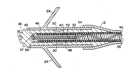
one or more slack filaments 40 within the insulating sheath 12
of the lead depicted in FIGS. l and 2 and wound loosely about
the coil 54 of at least one of the coiled wire conductors in
either a unipolar embodiment as depicted in FIG. l or in
bipolar and multipolar embodiments thereof. In FIG. 3, the
slack, loosely wound, filament 40 is shown in a partial
schematic view of its orientation to the coiled wire conductor
54 merely to illustrate that the filament or filaments are
intentionally loosely wound around either the inner or outer
coiled wire conductor to allow the lead to possess its normal
flexibility and springiness in its normal intended usage in
the implantation depicted, for example, in FIG. 2.
The filament 40 extends between the connector 16 at the
proximal end of the lead lO and the tip electrode 26 at the
distal end of the lead depicted in FIG. 1 and wit~in the
insulating sheath 12. When the lead body is stretched to
approximately 110% to 120% of its normal relaxed length, the
filament draws tight against the coiled wire conductors and
prevents further stretching of the lead body, unless it is
subjected to a pulling force far in excess of most manual
traction situations, such as more than 20-30 lbs. of axially
applied force.
- Preferably, filaments 40 are lengths of Dacron woven yarn
of relatively small cross-sectional area. A yarn, as opposed
to a monofilament, is preferred that possesses the requisite
strength, will flatten out in a constrained space and is not
susceptible to stretching, but will instead break at the
desired 20 lbs. traction applied to the lead body.
Turning now to FIGS. 4 and 5, alternative attachment
mechanisms are depicted for attaching one or more filaments 40
to the shank 46 of the distal electrode 26. The distal
WO93/148t1 11 210 4 ~ r~ 1 PCT/US92/10132
electrode 26 preferably takes the form of that electrode shown
in U.S. Patent No. 4,502,492 incorporated herein by reference.
FIG. 4 shows a cross-sectional view of the distal end of
the lead of FIG. 1. In this view, electrode 26 is seen to be
provided with an elongated, proximally extending tubular shank
46 which has a central lumen 56. Mounted within lumen 56 are
swaging pin 48 and coiled conductor 54. Crimps 50 maintain
coiled conductor 54 tightly fixed between swàging pin 48 and
tubular portion 46 of electrode 26. This structure provides
mechanical and electrical coupling of conductor 54 to
electrode 26. Coiled conductor 54 extends proximally within
insulating sheath 12 to the proximal end of the lead and is
coupled to connector pin 20 (FIG. 1). Swaging pin 48 is
provided with a central lumen 52 into which a stylet may be
inserted. Coiled conductor 54 may be fabricated of MP35N
alloy or other suitable conductive material, and is preferably
a multifilar coil as shown in FIG. 3. Swaging pin 48 may be
fabricated of stainless steel or other appropriate metal.
Electrode 26 is preferably constructed of or provided with a
coating of platinum or of a platinum alloy, but may also be
constructed of titanium, rhodium, iridium, or alloys thereof.
In order to accommodate the filaments 40, 41, the distal
end of the lead of FIGS. 1 and 2 as described in the
aforementioned '492 patent is modified as depicted in FIG. 4
to provide a hole 45 through the tubular shank portion 46
extending between recesses 47, 49 distal to the crimps 50.
The filament ends 42, 43 of filaments 40, 41 are threaded in
opposite directions through hole 45 and tied off and fitted
within the recesses 47 and 49 of the tubular portion 46. The
recesses 47, 49 and hole 45 may or may not be filled with
epoxy cement to stabilize the filaments 40, 41 in hole 45 and
reces6es 47 and 49.
The filaments 40, 41 extends along the outer surface of
the tubular shank portion 46 and within the tine sheath 22 and
WO93/14811 PCT/US92/10132
210 ~g6 1 12
through grooves cut in the shank ridge at 51, 53 whereafter it
is wound loosely about the coil 54 as shown in FIG. 3 through
the length of the lead body. A single filament could be
employed in the same fashion as shown in the partial
cross-sectional view of FIG. 4.
Turning now to FIG. 5, a further embodiment of the
connection of the distal end of the filament with the shank of
the connector end is depicted. In FIG. 5, the filament 40
extends through the lumen 55 of the coiled wire conductor 54
throughout its length and through the lumen 52 of the swaging
pin 48. In assembly, the filament is threaded through the
lumen 52 and knotted at its distal end 42. A dab of epoxy may
be applied to the knot 42. The coiled wire conductor 54 is
slipped over the outer surface of the swaging pin 48, and the
assembly is inserted into the central lumen 56 of the
elongated shank tubular portion 46 to locate the knot 42 in
the end 57 of lumen 56. The mechanical and electrical
attachment is completed in the manner described above by
swaging at points 50. In this embodiment, the filament
extends loosely down the lumen of the coiled wire conductor to
the connector where it is attached thereto.
Turning now to FIGS. 6 and 7, the connector end of the
lead of FIGS. 1 and 2 is depicted in partial cross-section to
illustrate the fashion in which the proximal end of the
filaments 40, 41 may be attached thereto. FIG. 6 is a
modification of FIG. 2 of U.S. Patent No. 4,944,088
incorporated herein by reference in its entirety. Basically,
the filaments 40, 41 actually constitute a single length of
filament which are passed through holes 100, 102, in a ring
element 144 and wound about the inner coil 134 or sheath 114
to extend between the coil 134 and the inner sheath 114 or the
outer sheath 128 through the length of the lead body. In the
bipolar lead embodiments, the filaments 40, 41 may be loosely
wound about either the inner sheath or coil and connected at
the distal tip electrode in the fashion depicted, e.g., in
... . . , , , , ~
`WO 93/14811 13 21~ PCT/US92/10132
FIG. 4 as described above. It will be understood that the
filaments 40, 41 could be threaded through a similar
connection in a unipolar connector and with or without the
inner sheath 114.
Turning now specifically to FIG. 6, it shows a
cross-sectional view of the proximal portion of a bipolar
connector assembly showing the interconnection of the
multiconductor coil 134 with the other components of the
connector assembly. Multiconductor coil 134 includes a first
coil conductor coupled to connector pin 124 and a second coil
conductor electrically coupled to ring member
122.
The connector assembly is fabricated by first laser
welding ring member 122 to cylindrical member 136 by means of
a circumferential laser weld at 138 to form a connector ring
assembly. Assembled ring member 122 and cylindrical member
136 are assembled over connector pin 124, placed into a mold,
and insulative sleeve 126 is then injection molded between
them. This process is disclosed in more detail in Hess U.S.
Patent No. 4,572,605, and incorporated herein by reference in
its entirety.
The complete assembly of connector pin 124, insulative
sleeve 126, ring member 122 and tubular member 136 is then
coupled to one conductor 140 of multiconductor coil 134.
Conductor 140 is screwed onto the distal end of connector pin
124, with protrusion 142 acting as a screw thread. Conductor
140 is screwed onto connector pin 124 until its proximal end
abuts against circular flange 144. Conductor 140 is then
coupled to circular flange 144 at 146 by means of a spot laser
weld. The spacing of intermediate circular flange 144 and
protrusion 142 allows for a limited amount of strain relief
immediately distal to the spot laser weld at 146.
Tubular extension 148, which takes the form o$ a cylinder
having an extended longitudinal slot 150 is then slid over the
distal end of cylindrical member 136 and coupled to it by
- ;,:, : ~ : . .,, ~ . ,
WO93/14811 , PCT/US92t10132
14
2~ ~861
means of a circumferential laser weld at 153. A shallow
grooved section 152, having a groove that corresponds
generally to the size of conductor 154, is located at the
proximal end of slot 150 in tubular extension 148. Conductor
154 is stripped of insulation and laid lengthwise in the
grooved area 152, and laser welded to extension 148.
Following this step, insulative sleeve 128 is slid over
extension 148 and over cylindrical member 136. Member 136 is
provided with a cross bore 156, which may be filled with
medical adhesive, thereby bonding insulative sleeve 128 to
insulative sleeve 126.
Finally, the entire assembly is backfilled with adhesive
injected between insulative sheath 114 and insulative sleeve
128, filling the area between insulative sleeve 128 and sheath
114, as well as the lumen 158 of sleeve 128 and the lumen 160
of tubular extension 148. This serves to bond the components
of the connector assembly to one another and to insulative
sleeve 128 and to electrically insulate the conductor 140 and
connector pin 124 from the conductor 154. For the sake of
clarity, the backfilled adhesive is not shown in this
illustration. Mounted within multiconductor coil 134 is a
Teflon0 plastic liner 162, which serves as a passageway for a
stylet. The internal lumen of liner 62 is align,ed with the
internal bore 164 of connector pin 124.
As stated hereinbefore, the filaments 40, 41 in this
embodiment actually comprise a single filament threaded
through holes 100, 102 shown in the cross-sectional view of
FIG. 7 extending through the circular flange 144 in and out of
holes 100 and 102. It will be appreciated that a single
filament could be passed through the holes 100, 102 and tied
off, rather than looped back as the second filament as shown
in FIG. 6. It will also be appreciated that the filament or
filaments may be looped through holes in other parts of the
proximal lead assembly of FIG. 6, such as holes passi,ng
through the sidewalls of tubular extension 148.
. .. , .. . ., . . " . .. . . . ,. . . . ~ . . . ,. . . ~
WO93/14811 lS 2 1 o ~ ~ ~ t PcT/us92~lo132
The connector end as described above in conjunction with
FIGS. 6 and 7 involves the implementation of the invention in
the context of the above-incorporated '088 patent where the
individual conductors of multiconductor coil 134 are
separately insulated and connected to connector pin 124 and
ring 122. It will be understood that the same attachment of
the filaments 40, 41 through the flange 144 may be 1,
accomplished in less compiex connectors where all of the
multifilar, coaxial conductors are electrically and
mechanically connected to the connector pin 124 and the
tubular extension 148 and its attachment to one of the
conductors of coil 134 is eliminated. In such embodiments,
the flange 144 is present and functions as described above,
but it may have a larger relative diameter than illustrated in
FIG. 6.
In the embodiment of FIG. 5, where the filament 40
extends through the lumen 55 of the coiled wire conductor 54,
the proximal end of the filament 40 would be drawn through a
spaced apart turn of the multifilar coil 134 at its juncture
with the distal end of the connector pin 124 and attached in
the same fashion as depicted in FIGS. 6 and 7 and described
above. Other mechanisms for attaching the proximal and distal
ends of the filament will be apparent to those of skill in the
art and depend upon particular attachment configurations of
existing and future lead designs.
Turning now to FIG. 8, it depicts in partial side
elevation view, the arrangement of a loosely wound, coaxial,
tubular reinforcing sheath 66 fitted over the coiled wire
conductor 54 or the insulating sheath 114. It will be
appreciated that the loosely wound tubular sheath is an
extension of the number of filaments from one or two as
previously described but would employ a Dacron fabric having
individual webs of a greater width than thickness and which
would be capable of being stretched a certain amount until its
shrinking inner diameter would firmly grip the outer surface
.:
~ .
W093/14811 ~ PCT/US9V10132
21~48~ 16
of the coiled wire conductor 54 or the insulating sheath 114.
Thus, the reinforcing sheath 66 would operate in the fashion
of a Chinese finger pull toy on the underlying coil or
insulating sheath.
Turning now to FIG. 9, a cross-sectional sideview of a
distal tip similar to the distal tips depicted in FIGs. 4 and
5 illustrates one manner of attaching the loosely woven,
criss-crossed or braided reinforcing sheath 66. In this
embodiment, the loosely woven sheath 66 is fitted over the
inner insulating sheath 114 and inside the outer insulating
sheath 12. The distal end of the tubular reinforcing sheath
66 is fitted over the flange of the tubular shank 46 which
itself forms the distal electrode 26 as described above. The
distal end of the tubular sheath 66 is pressed against the
periphery of the shank 46 by a layer of heat shrink tubing 70
which extends over a predetermined length of the distal end of
the sheath 66 after it is itself fitted over the shank 46 and
heat shrunk in place. Thereafter, the outer insulating sheath
12 is placed over the assembly to further strengthen and
insulate the lead body.
The connection of the loosely woven, reinforcing sheath
66 at the proximal, connector end of the lead of FIGS. 8 and
9 is depicted schematically in FIG. 10. FIG. 10 generally
corresponds in structure to FIG. 6 except that conductive tube
154 is not present (as suggested above) and inner sheath 114
extends over the inner conductor coil and its attachment to
connector pin 124. The loosely woven sheath 66 extends over
inner sheath 114 and inside outer connector sheath 128. The
space 180 within the outer connector sheath 128 would be
filled with adhesive to fix the components together when
traction is placed on the lead as described above. The
adhesion of the sheath 66 to the connector structure may also
be achieved through other means, including heat shrink wrap
tubing as described in connection with FIG. 9.
...... ~
WO93/14811 17 2 1 o ~ PCT/US92/tO132
In a still further embodiment, it is contemplated that
the reinforcing sheath 66 or the filaments 40, 41 may be
embedded on a surface of or within an insulating sheath
through the length of the lead body such that the sheath may
be stretched to only a predetermined stretched length
exceeding its normal relaxed length during application of
traction forces.
Many other benefits also follow from the present
invention. For example, the novel lead body reinforcement
structure described herein also provides additional tensile
support at the distal end of the lead body, which can ~e
particularly useful for the physician who encounters, during
- a lead replacement procedure, an occasionally stubborn
pacemaker connector block/pacing lead connector which requires
significant pulling force to separate the lead from the
pacemaker. FinaIly, the limited extensibility provided by
claimed lead body reinforcement structure also provides
benefit to the patient who may encounter a physically
traumatic event, such as a fall, or an automobile accident, to
the extent that the lead body can accommodate whatever stress
may be exerted upon the lead body by allowing moderate lead
body stretching without incurring lead damage or dislodgement.
Although the particular embodiments disclosed in this
application take the form of cardiac pacing leads, the
inventions disclosed hereon are believed equally applicable to
medical electrical leads in general.