Note: Descriptions are shown in the official language in which they were submitted.
(Case No. 8725) ~ 5 ~
IMPROVED CHARGING CUT-OFF VALVE ARRANGEMENT FOR
MICROPROCESSOR-BASED ELECTROPNEUMATIC LOCOMOTIVE
BRAKE CONTROL SYSTEM
BACKGROUND OF THE INVENTION
The present invention relates to microprocessor-
based electropneumatic type locomotive brake control
systems and particularly to an improved brake pipe
charging cut-off valve arrangement for such a locomotive
brake control system.
Modern-day locomotive controls, including the
locomotive brake control system, incorporate computer
technology to reduce hardware and to facilitate
adaptation of the system to various customer
requirements.
In one such brake control system, described in U.S
Patent No. 5,222,788 i~ued Augu~t 30, 1993, a cab-mounted, handle-
operated, brake controller outputs a desired brake
command signal to a microprocessor unit, which interprets
this brake command signal in terms of a feedback signal
indicative of the pressure of air in an equalizing
reservoir, and then effects operation of application and
release electropneumatic valves to adjust the equalizing
reservoir pressure in accordance with the brake command
signal.
A high-capacity pneumatic relay valve device is
employed to vary the trainline brake pipe pressure in
21~5~
accordance with variations of the equalizing reservoir
pressure, in order to control the railway car brakes.
This so-called brake pipe control circuit of the afore-
mentioned brake control system is shown and described in
U.S. Patent No. 4,904,027.
The brake control system further includes a
locomotive brake cylinder control circuit having
electropneumatic application and release valves. The
locomotive brake cylinder control electropneumatic valves
are operated by the microprocessor in response to changes
in brake pipe pressure initiated by the brake pipe
control circuit in accordance with movement of an
automatic brake handle of the cab brake controller.
Another high-capacity pneumatic relay valve device
controls the pressure in the locomotive brake cylinders
according to the pressure output of the locomotive brake
cylinder control circuit application and release
electropneumatic valves.
The electropneumatic valves in the brake pipe
control circuit and in the locomotive brake cylinder
control circuit are arranged to assume a pressure release
state, in the event of a power loss at the microprocessor
unit. In consequence of such a power loss, therefore,
brake pipe pressure is reduced while, concurrently, the
locomotive brake cylinder pressure is released. A
pneumatic back-up control valve in the locomotive
~iO~
automatic brake control circuit is provided to establish
locomotive brake cylinder pressure in response to the
afore-mentioned reduction of brake pipe pressure
resulting from such fail-safe operation of the
electropneumatic valves in the brake pipe pressure
control circuit, there being a double check valve to
separate the pneumatic backup control valve from the
electropneumatic valves in the locomotive brake cylinder
control circuit.
lo Additional electropneumatic valves are employed in
conjunction with a charging cut-off valve in a branch
pipe via which the brake pipe pressure control circuit is
connected to the locomotive brake pipe. The charging
cut-off valve is provided to establish communication
between the brake pipe pressure control circuit and the
brake pipe when the locomotive is set up for "lead"
operation, as a controlling locomotive, and to interrupt
such communication when the locomotive is set up for
"trail" operation, as a non-controlling locomotive.
The afore-mentioned charging cut-off valve is
bistable and thus remains in its set position in the
event of a microprocessor malfunction that causes a loss
of power. In the event such a malfunction occurs on a
controlling locomotive that is subsequently downgraded to
non-controlling status, it will be appreciated that the
charging cut-off valve remains in its previously set open
21~SlS~
position. Typically, such a non-controlling locomotive
is hauled "dead", i.e., without electrical power, whereby
the application and release electropneumatic valves in
the brake pipe pressure control circuit are de-energized.
This in turn causes the relay valve in this control
circuit to assume an exhaust condition, thereby venting
the brake pipe via the open charging cut-off valve.
Accordingly, the ability to recharge the brake pipe from
another controlling locomotive, following a "loss of
~0 power" brake application, could be jeopardized.
SUMMARY OF THE INVENTION
It is, therefore, the object of the present
invention to provide a charging cut-off valve having a
normally closed condition to which the valve reverts in
the absence of microprocessor power, except when a
locomotive is operating in a controlling mode, or when a
locomotive having microprocessor power is operating in a
non-controlling mode.
Briefly, there is provided in a microprocessor-based
locomotive brake control system a brake pipe charging
cut-off arrangement comprising, in addition to the
locomotive brake pipe, a source of fluid under pressure;
regulator means via which the brake pipe pressure is
provided in accordance with a certain chosen control
pressure; a charging cut-off valve having an open
position for providing fluid pressure communication
210~
between the regulator means and brake pipe, and a closed
position for interrupting fluid pressure communication
therebetween; selector means for establishing the
charging cut-off valve open and closed positions in
accordance with a desired controlling or non-controlling
mode of locomotive operation; a microprocessor for
providing electric power to the regulator and selector
means; a lead and trail electropneumatic valve, each
having a supply port to which the fluid pressure source
is connected and a delivery port communicated with said
supply port in an energized condition thereof and to
atmosphere in a de-energized condition thereof; and
switch means for connecting electric power from the
microprocessor to either one of the lead and trail
electropneumatic valves, while concurrently cutting off
electric power from the microprocessor to the other of
the lead and trail electropneumatic valves to establish
the afore-mentioned controlling and non-controlling modes
of locomotive operation, the lead electropneumatic valve
being energized in the controlling mode and the trail
electropneumatic valve being energized in the non-
controlling mode; bias means for urging the charging cut-
off valve toward the closed position so that, in the
absence of electric power at the regulator means and both
of the lead and trail electropneumatic valves, fluid
pressure communication between the brake pipe and
210S151
regulator means is interrupted; and sensing means for
maintaining the charging cut-off valve in its open
position in opposition to the bias means in accordance
with loss of electric power from the microprocessor when
the locomotive is in a controlling mode.
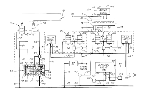
DESCRIPTION OF THE INVENTION
Referring to the drawing, there is shown a
locomotive electropneumatic brake control system having a
microprocessor 2 that controls a brake pipe pressure
control circuit 4, a locomotive brake cylinder control
circuit 6, and a brake pipe charging cut-off control
circuit 8. Microprocessor 2 receives input signals from
a cab brake controller 10 having an automatic brake
control handle 12 and an independent brake control
handle 14.
Manual operation of automatic brake control handle
12 into the service brake zone between brake release and
full service positions establishes a level of brake pipe
pressure corresponding to a desired level of brake
application. The handle position in the service zone is
converted into a corresponding electrical brake command
signal by a suitable encoder, or the like, which is fed
to microprocessor 2 via line 16. Microprocessor 2
responds to this brake command signal and generates a
2S regulated 24-volt output signal at wires 18,20 via which
the solenoid operators of two-way, spring-returned,
213~
charging and release electropneumatic valves 22,24 are
actuated. Charging valve 22 is normally closed and
release valve 24 is normally open, the inlet P of
charging valve 22 being connected by a pipe 26 to a main
reservoir 27 to which air is supplied from a compressor
(not shown), and the outlet A of release valve 24 being
connected to atmosphere. Main reservoir 27 is connected
by a pipe 38 to a main reservoir equalizing pipe 30 that
is interconnected between the units of a locomotive
consist. A control reservoir 28 is connected to a pipe
29 via which outlet A of charging valve 22 is connected
to inlet P of release valve 24. A pressure transducer T1
monitors the pressure in control reservoir 28 and
transmits a corresponding feedback signal to
microprocessor 2 via wire 32.
The control port of a high capacity pneumatic relay
valve 34 is connected by a pipe 36 to control reservoir
28. Relay valve 34 may be a conventional, well-known C-2
type relay valve typically employed in the 26 type
locomotive brake valves and also in the 30-CW module
manufactured by the Westinghouse Air Brake Company.
Relay valve 34 further includes a supply port that is
connected by pipe 26 to main reservoir 27, a delivery
port that is connected by a pipe 41, 41a to brake pipe 40
via a charging cut-off valve 68 of charging cut-off
control circuit 8, and an exhaust port 44 that is
2 1 ~
connected to atmosphere. Charging cut-off valve 68 is
open on controlling locomotive units to establish
communication between brake pipe 40 and relay valve 34
and closed on non-controlling units to interrupt such
5 communication. Relay valve 34 operates in accordance
with the pressure in control reservoir 28, supplying air
from main reservoir 27 to pipe 41 or releasing air from
brake pipe 40 via pipe 41 and exhaust port 44. The train
brake pipe 40 carries compressed air to the cars in the
train, the brakes of which are controlled in accordance
with variations of such brake pipe pressure in a well-
known manner.
The locomotive brake cylinder control circuit 6 is
controlled in accordance with the brake pipe pressure, as
15 monitored by a transducer T4, which transmits a
corresponding electrical feedback signal via wire 45 to
microprocessor 2. This permits the microprocessor to
establish the locomotive brake cylinder pressure.
Locomotive automatic brake control circuit 6
20 consists of a normally closed, two-way, spring-returned,
electropneumatic application valve 46, a normally open,
two-way, spring-returned, electropneumatic release valve
48, a control reservoir 50 and a pressure transducer T6.
Inlet P of application valve 46 is connected via pipe 26
25 to main reservoir 27, while outlet A of release valve 48
is connected to atmosphere. Reservoir 50 is
~lOSlSl
interconnected between outlet A of application valve 46
and inlet P of release valve 48 via a pipe 49.
Transducer T6 instantaneously monitors the pressure in
reservoir 50 and transmits a corresponding electrical
S feedback signal to microprocessor 2 via wire 52. The
solenoid operators of the respective application and
release valves 46,48 are connected by wires, 54,56 to
microprocessor 2, which is capable of supplying 24 volts
to these control wires under normal operating conditions.
The pressure in control reservoir 50 is regulated by
these electropneumatic application and release valves in
inverse relationship and at a predetermined ratio
relative to brake pipe pressure changes. Reservoir 50 is
connected by a pipe 58 to one inlet of a double check
valve 60, the outlet of which is connected by a pipe 61
to the control port of a high capacity pneumatic relay
valve 62. This relay valve 62 may be a well-known,
standard J-type relay valve device manufactured by the
Westinghouse Air Brake Company, further having a supply
port that is connected by pipe 26 to main reservoir 27, a
delivery port that is connected by a pipe 64 to the
locomotive brake cylinder device 65, and an exhaust port
66 that is connected to atmosphere. Relay valve 62
provides the required high capacity to supply compressed
air from main reservoir pipe 26 to brake cylinder device
65, and to release brake cylinder pressure via exhaust
port 66, in accordance with the pressure level
established in reservoir 50.
The locomotive brake cylinder control circuit 6 is
further provided with a pneumatic back-up automatic brake
S control valve 110. This brake control valve 110 may be a
basic MC-30C type control valve device that is well known
in the railroad braking industry, being manufactured by
the Westinghouse Air Brake Company, and shown and
described in Operation and Maintenance brochure 4220-5,
published by the Westinghouse Air Brake Company.
As shown in the drawing, brake control valve 110
includes a supply port 111 to which an auxiliary
reservoir 113 is connected via a pipe 115, a control port
117 to which brake pipe 40 is connected via a pipe 119, a
delivery port 125 connected to the other inlet of double
check valve 60 by a pipe 129, and an exhaust port 131
that is connected to atmosphere. Connected to pipe 129
is a displacement reservoir 133 that simulates the brake
cylinder volume to assure proper operation of control
valve 110.
In charging cut-off control circuit 8, charging cut-
off valve 68 includes a piston 69 having a stem 70 to
which a poppet valve element 71 is connected. A chamber
73 having a port 72 is formed on one side of piston 69,
being subject to compressed air which acts in concert
with a bias spring 74 to urge piston 69 in a right-hand
21 051Sl
direction, in which poppet valve element 71 is engaged
with a seat 75 that surrounds a supply port 76, thereby
establishing the closed condition of cut-off valve 68.
Another chamber 77 is formed on the opposite side of
piston 69, being subject to compressed air connected via
a port 78 to urge piston 69 in a leftward direction in
which poppet valve element 71 is disengaged from seat 75,
thereby establishing the open position of cut-off valve
68.
Also included in charging cut-off control circuit 8
are solenoid operated, spring-returned, "trail" and
"lead" electropneumatic valves 79 an'd 80, respectively,
the solenoid operator of these valves being connected to
microprocessor 2 via wire 90 and a two-position selector
switch 91 that, in actual practice, is integrated in
microprocessor 2 and establishes the "lead" or "trail"
status of the locomotive. Electropneumatic valves 79 and
80 are two-position, 3-way valves having a normally
closed inlet P and a normally vented outlet A, in
accordance with a de-energized condition of the solenoid
operator. In the energized condition, outlet A is cut
off from atmosphere and connected to inlet P, the inlet P
of each valve 79,80 being connected by a pipe 81 to main
reservoir pipe 30. Outlet A of "trail" electromagnetic
valve 79 is connected by a pipe 82 to port 72 of cut-off
valve 68, and outlet A of "lead" electropneumatic
2105151
valve 80 is connected by a pipe 83 to one inlet of a
double check valve device 84, the outlet of which is
connected by a pipe 85 to port 78 of cut-off valve 68.
The other inlet of double check valve device 84 is
connected by a pipe 86 and a port 87 to an interlock
chamber 88 of charging cut-off valve 68 in which poppet
valve 71/75 is disposed. This interlock chamber 88 is
connected to brake pipe 40 via a port 89 and pipe 41a.
INITIAL CHARGING
Prior to initial charging, i.e., prior to power
being supplied to microprocessor 2, the electropneumatic
valves in the respective brake control circuits 4, 6, and
8 are de-energized, and accordingly assume a normal
position, as shown, under the influence of their return
springs. Consequently, control reservoir 28 is vented to
atmosphere via outlet A of release valve 24.
When power is subsequently turned on and handle 12
on the controlling locomotive brake controller 10 is
moved to release position to initiate charging, a
20 difference exists between the brake command signal
transmitted to microprocessor 2 via wire 16, in
accordance with the position of handle 12 and the
feedback signal transmitted from transducer Tl to
microprocessor 2 via wire 32, indicative of the pressure
25 level of control reservoir 28. The polarity of this
signal difference causes microprocessor 2 to energize
12
C~ 5 ~
electromagnetic application and release valves 22, 24, of
the brake pipe control circuit 4, thereby causing these
valves to be shifted from their normal de-energized
positions, as represented by the connections shown in the
lower valve envelope, to the position represented in the
upper valve envelope. Consequently, compressed air is
connected from main reservoir 27 to control volume 28 via
pipe 26, ports P and A of application valve 22 and pipe
29, this pressure in pipe 29 being cut off from
atmosphere at port P of release valve 24.
When the pressure in control reservoir 28, as
monitored by transducer Tl, corresponds substantially to
the brake command signal at wire 16, microprocessor 2 de-
energi~es application valve 22, while maintaining release
valve 24 energized. This establishes a lap condition in
which further supply and release of control reservoir 28
pressure is terminated, it being understood that as the
cdntrol reservoir pressure approaches the command
pressure, application valve 22 is controlled in
accordance with the afore-mentioned Patent No. 4,904,027,
in order to prevent overshoot and consequent valve
cycling.
This control re~ervoir pressure is in turn connected
via pipe 36 to relay valve 34, which in turn supplies air
from main reservoir 27 to pipe 41 and the charging cut-
off valve 68.
21~51!~1
Brake pipe charging cut-off control circuit 8 is set
up to either open or close charging cut-off valve 68,
depending upon the "lead" or "trail" status of the
locomotive, in order to establish or interrupt the
charging of brake pipe 40. On the controlling
locomotive, selector switch 91 is set in "lead" position,
thereby connecting microprocessor power from wire 90 to
the solenoid of electropneumatic valve 80, while
concurrently disconnecting microprocessor power to the
solenoid of electropneumatic valve 79. In its energized
condition, electropneumatic valve 80 connects inlet P to
outlet A. Consequently, charging cut-off valve chamber
77 is supplied with main reservoir air via locomotive
main reservoir pipe 30, pipe 81, valve 80, pipe 83,
double check valve 84, and pipe 85; while chamber 73
remains vented via pipe 82 and de-energized
electropneumatic valve 79. The main reservoir air
pressure effective in chamber 77 develops a force on
piston 69 to overcome bias spring 74 and shift piston 69
in a leftward direction in which poppet valve element 71
is disengaged from seat 75, thereby establishing the open
condition of cut-off valve 68 to accommodate the charging
of brake pipe 40 to a predetermined running pressure
which can be adjusted at microprocessor 2, as desired.
On non-controlling locomotives, selector switch 91
is set in "trail" position and brake pipe charging
21051~1
cut-off control circuit 8 is accordingly set up to
energize the solenoid operator of electromagnetic valve
79 and to de-energize the solenoid of electropneumatic
valve 80. In its energized condition, electromagnetic
valve 79 connects inlet P to outlet A. Consequently,
charging cut-off valve chamber 73 is supplied with main
reservoir air pressure via locomotive main reservoir pipe
30, pipe 81, the energized electropneumatic valve 79, and
pipe 82. The force of this pressure acting on piston 69
combined with the force of spring 74 effects closure of
valve element 71 to prevent charging of brake pipe
pressure from the non-controlling locomotive.
Concurrently, de-energized electropneumatic valve 80
vents pipe 83 leading to inlet 84 of double check valve
84, which accordingly connects brake pipe pressure from
pipe 41a, charging cut-off valve interlock chamber 88 and
pipe 86 to pipe 85 and chamber 77, as the brake pipe is
charged. The pressure in chamber 77 acts on an area of
piston 69 reduced by the area of stem 70, this reduced
differential piston area being compensated by the
differential area of valve element 71 subject to the
pressure in chamber 88 and port 76. However, since the
main reservoir pressure in chamber 73 is greater than the
opposing brake pipe pressure in chambers 77 and 88/76,
the fluid pressure force, in addition to the force of
spring 74 acting on the piston assembly, maintains
closure of cut-off valve 68.
-
On a locomotive hauled dead in the locomotive
consist, electropneumatic valves 79,80 are both de-
energized, since power is unavailable on the dead
locomotive. Thus, both chambers 73 and 77 of charging
cut-off valve 68 are vented via the respective
electropneumatic valves 79 and 80. Chamber 77, however,
is supplied with brake pipe pressure via double check
valve 84. Since electropneumatic valves 22,24 are de-
energized, relay valve 34 is effective to vent pressure
at port 76 of the charging cut-off valve 68. Being
normally in a closed condition due to spring 74, valve
element 71 cuts off the exhaust of brake pipe pressure
via the relay valve. Moreover, the absence of pressure
at port 76 acting on valve element 71 within the area
delineated by valve seat 75 establishes a force
differential on valve element 71 which urges piston 69 in
the same direction as spring 74 to maintain closure of
valve 71/75 in opposition to the brake pipe pressure in
chamber 77 acting thereon. It will be appreciated that
spring 74 and the pressure areas of stem 70 and valve
element 71 within the area of seat 75 are chosen to
assure such valve closure.
Brake pipe pressure in pipe 40 is concurrently
supplied via pipe 119 and controlport 117 to control
valve 110, which accordingly assumes a release position.
Brake cylinder control pressure in pipe 129 and
11 5 ~ ~
displacement reservoir 133 is thus vented via delivery
port 125 and exhaust port 131.
Further, during charging of brake pipe 40,
transducer T4 transmits a feedback signal to
microprocessor 2 via wire 45. While the charging brake
pipe pressure builds up to a value corresponding to a
reference signal that is stored in microprocessor 2
representing the desired running or charge pressure of
the train, application and release valves 46,48 of
locomotive automatic brake control circuit 6 remain de-
energized, as shown. In this de-energized condition,
application valve 46 interrupts the supply of main
reservoir air to control reservoir 50 by disconnecting
its inlet and outlet ports P, A, and release valve 48
connects control reservoir 50 to atmosphere via pipe 49
and its connected inlet and outlet ports P, A.
It will be appreciated from the foregoing that
control pipe 61 of relay valve 62 is vented via double
check valve 60 and either pipe 58 leading to the vented
control reservoir 50 or pipe 129 leading to control valve
110. Brake cylinder 65 is accordingly vented via exhaust
port 66 to maintain the locomotive brakes released during
this charging of the brake pipe.
AUTOMATIC APPLICATION OF CAR BRAKES
Following charging of brake pipe 40, a brake
application may be initiated on the cars of the train by
210~51
movement of automatic handle 12 out of release position
into the service application zone on the lead or
controlling locomotive. The handle position is encoded
and fed to microprocessor 2 via wire 16. The difference
between the electrical brake command signal at wire 16
and the electrical feedback signal at wire 32 causes
microprocessor 2 to de-energize wire 20 while also
maintaining wire 18 de-energized. Application valve 22
thus continues to interrupt the supply of main reservoir
pressure at inlet P thereof, while release valve 24
transitions to the position shown, in which its inlet P
is connected to outlet A. The pressure in control
reservoir 28 is thus released to atmosphere via pipe 29
and release valve 24 until the signals at wires 16 and 32
substantially correspond. When this occurs,
microprocessor 2 causes wire 18 to remain de-energized,
while energizing wire 20. Consequently, both the
application valve 22 and the release valve 24 assume a
closed or lap state in which no further change in control
reservoir pressure occurs.
The resultant reduction of control reservoir
pressure is reflected at the control port of relay valve
34, which, in turn, operates to vent brake pipe 40 via
branch pipe 41a, the open charging cut-off valve 68 at
the lead or controlling locomotive unit, pipe 41 and
exhaust port 44 of relay valve 34. Pressure in the
2lo5l5l
trainline brake pipe 40 is thus reduced in accordance
with the pressure reduction of control reservoir 28 to
cause a brake application on the cars of the train in
accordance with the selected position of brake controller
automatic handle 12 in the service brake zone.
AUTOMATIC APPLICATION OF LOCOMOTIVE BRAKE
Concurrently, an electrical feedback signal is
transmitted to microprocessor 2 at both the controlling
and non-controlling locomotives via transducer T4 and
wire 45 corresponding to the instantaneous pressure in
brake pipe 40. Since this brake pipe feedback signal at
wire 45 is less than the reference signal at
microprocessor 2, the locomotive automatic brake control
circuit 6 is activated to effect energization of
application valve 46 and release valve 48 via wires 54
and 56. Application valve 46 is shifted to its open
position, in which inlet P is connected to outlet A,
while release valve 48 is shifted to its closed position,
in which outlet A is cut off from inlet P. Main
reservoir pressure is thus supplied to control reservoir
50 via pipe 26, application valve 46, and pipe 49, until
such time as the electrical feedback signal from
transducer T6 to microprocessor 2 via wire 52 increases
in proportion to the brake pipe pressure reduction in
effect. It will be appreciated that microprocessor 2
establishes this control of the application and release
19
21~5151
valves 46, 48 of locomotive automatic brake control
circuit 6, such that the pressure of control reservoir 50
varies inversely with the brake pipe pressure reduction
in a ratio of approximately 2.5:1.
The resultant pressure developed in control
reservoir 50 is connected to the control port of relay
valve 62 via pipe 58, double check valve 60 and pipe 61.
Relay valve 62, in turn, operates to supply air from main
reservoir 27 to brake cylinder 65 via pipe 26 and
delivery pipe 64. In this manner, the controlling and
non-controlling locomotive brake pressure under control
of brake control circuit 6 is consistent with the car
brake pressure under control of the controlling
locomotive brake pipe control circuit 4.
APPLICATION OF LOCOMOTIVE PNEUMATIC BACKUP BRAKE
Pneumatic control valve device 110 provides a backup
pneumatic automatic locomotive brake, operating in
parallel with automatic brake control circuit 6, in
response to variations in brake pipe pressure. A
reduction of brake pipe pressure, as explained relative
to applying the car brakes throughout the train, is
reflected at port 117 of control valve 110. In a manner
well known to those skilled in the railway braking art,
control valve device 110 is operative in response to such
reduction of brake pipe pressure to connect pressure in
auxiliary reservoir 113 to displacement reservoir 133 and
~i~5151
double check valve 60 via pipe 115, supply port 111,
delivery port 125, and pipe 129. Due to the inherent
delay in operation of control valve device 110, the
pressure in pipe 58 under control of automatic brake
control circuit 6 reaches double check valve 60 before
the pressure in pipe 129, thus holding the pneumatic
backup control valve pressure in abeyance pending failure
of the automatic brake control circuit 6, due to a
microprocessor malfunction, for example, or when the
locomotive is hauled "dead" in the locomotive consist, as
will be hereinafter explained.
MICROPROCESSOR MALFUNCTION ON CONTROLLING LOCOMOTIVE
In the event of a malfunction that would render the
controlling locomotive microprocessor 2 incapable of
providing power to operate the respective
electropneumatic valves heretofore discussed, the
controlling locomotive will initiate a brake application
automatically in response to the electropneumatic valves
22,24 in the controlling locomotive brake pipe control
circuit 4 assuming a de-energized condition, as shown.
Therefore, irrespective of the position of brake
controller handle 12, such loss of power causes control
reservoir 28 to be exhausted via release valve 24. Relay
valve 34, in turn, is operated to exhaust brake pipe
pressure via charging cut-off valve 68, such reduction of
brake pipe pressure accordingly initiating a brake
wlû5151
application on the cars of the train in the usual, well-
known manner.
It will now be appreciated that, in accordance with
the present invention, the controlling locomotive
5 charging cut-off valve 68 will remain in its open
position, irrespective of the aforementioned loss of
power at the controlling locomotive microprocessor 2.
Such loss of power at microprocessor 2 effects de-
energization of "lead" electropneumatic valve 80, thereby
venting pipe 83 at one inlet of double check valve 84.
Pressure in brake pipe 40, which is present at the other
inlet of double check valve 84 via branch pipe 41a,
charging cut-off valve port 89, interlock chamber 88,
port 87, and pipe 86, is thus connected through the
double check valve to pipe 85, charging cut-off valve
port 78, and chamber 77. In thus maintaining
pressurization of this chamber 77, charging cut-off valve
piston 69 continues to be forced leftward against bias
. spring 74 to effect disengagement of valve 71 from seat
20 75 and thereby establish the aforementioned open position
of cut-off valve 68 until such time as brake pipe
pressure is reduced to approximately 10-15 psi. It will
be understood that charging cut-off valve chamber 73
remains de-pressurized in accordance with the de-
energized condition of the "trail" electropneumatic valve79 to accommodate such leftward movement of piston 69.
2105151
Charging Cut-off valve 68 is, accordingly, held in its
open position to accommodate the reduction of brake pipe
pressure via relay valve 34.
This reduction of brake pipe pressure at the lead
locomotive concurrently effects operation of pneumatic
backup control valve 110, as previously explained, at the
lead locomotive to effect a brake application via relay
valve 62. Whereas this backup pneumatic brake control is
withheld under normal power conditions, by reason of the
locomotive brake cylinder control circuit 6 having
precedence, as explained, de-energization of
electropneumatic valves 46,48, due to the power loss at
microprocessor 2, causes control reservoir 50 to be
vented so that no pressure is supplied to double check
valve 60 via pipe 58. Consequently, control of the
locomotive automatic brake is established via pipe 129
leading to the other side of double check valve 60 at the
controlling locomotive to apply the locomotive brakes.
At the same time, the effective reduction of brake
pipe pressure causes the train brakes to apply, at each
car and/or locomotive not so electronically equipped, in
the usual, well-known manner to bring the train to a safe
halt.
It will be understood from the foregoing that,
without double check valve 84 and the feedback connection
of brake pipe pressure to cut-off valve chamber 77, this
21i)~1Sl
chamber 77 would be vented in the de-energized condition
of "lead" electropneumatic valve 80, allowing spring 74
to seat valve 71 and accordingly interrupt the exhaust of
brake pipe pressure via pipe 41, thereby isolating brake
pipe 40 from relay valve 34, whereby the desired
reduction of brake pipe pressure in accordance with such
loss of power would not be possible and no brake
application could be achieved.
It will be further understood that bias spring 74 is
necessary to assure closure of cut-off valve 68 under
certain situations in which the charging cut-off valve
could be open, while relay valve 34 is concurrently open
to atmosphere. Such a situation would allow brake pipe
pressure to escape to atmosphere. For example, following
a brake pipe initiated brake application in response to a
microprocessor power loss on a controlling locomotive, as
above explained, the brake pipe pressure will be
depleted, and must therefore be recharged to release the
train brakes in order to proceed. If the status of the
controlling locomotive experiencing the microprocessor
power loss is changed to "trail", so that it can be
hauled "dead" under control of another locomotive which
has been upgraded to controlling status, any attempt to
recharge brake pipe 40 to effect a release of the train
brakes could be nullified by the exhaust of brake pipe
pressure via the open charging cut-off valve 68 and relay
24
21~5151
valve 34 on the "dead" locomotive, without the provision
of bias spring 74 to assure closure of cut-off valve 68.
MICROPROCESSOR MALFUNCTION ON TRAIL LOCOMOTIVE
No brake application will occur in the event a
trailing locomotive microprocessor should experience a
malfunction, due to which the respective electropneumatic
valves 22,24 in brake pipe control circuit 4 and
electropneumatic valves 46,48 in the locomotive brake
cylinder control circuit 6 are without power. In
response to such power loss, pressure is exhausted from
charging cut-off valve chamber 73 via the vented
electropneumatic valve 79. Also, electropneumatic valve
80 vents pipe 83, but pressure in chamber 77 is
maintained by brake pipe pressure supplied thereto via
double check valve 84. While this creates a pressure
differential across piston 69, the concurrent exhaust of
pressure at port 76 of the charging cut-off valve 68 via
relay valve 34, in response to electropneumatic valve 24
venting control reservoir 28, creates a pressure
differential across valve element 71 abetted by spring 74
in the direction of valve closure. Consequently, the
opposing force on piston 69 due to the pressure effective
in chamber 77 is sufficiently counteracted that the force
exerted by spring 74 maintains closure of valve element
71. Since charging cut-off valve 68 is closed on a non-
controlling locomotive, the pressure reduction provided
2105151
by relay valve 34 is isolated from brake pipe 40, thereby
rendering a non-controlling locomotive unresponsive to
fail-safe operation of electropneumatic valves 22,24 in
brake pipe control circuit 4. Also, since
electropneumatic valves 46,48 are arranged to vent
reservoir 50, it will be appreciated that no brake will
be obtained through the non-controlling locomotive brake
cylinder control circuit 6, due to this trail locomotive
microprocessor power failure. Accordingly, the danger of
an unrecognized brake application existing on a trailing
locomotive is eliminated. However, backup control valve
110 remains available to furnish an automatic brake
application on the non-controlling locomotive unit when
so commanded by brake pipe reduction initiated from the
lead or controlling locomotive in the consist.
26