Note: Descriptions are shown in the official language in which they were submitted.
n ... ,. w ~ ,
' n
1 ~ !~
WO 92/15532 PCT/US92/01717
- 1 -
HIGH SHEAR MIXER AND GLASS MELTING
APPARATUS AND METHOD
TECHNICAL FIELD
The present invention relates to glass melting
methods and apparatus and mare particularly relates to
glass melting apparatus having a highly stirred portion
of the melt volume.
BACKGROUND OF INVENTION
Vitrification holds promise as an approach to
disposing of hazardous wastes and recycling glass
manufacturing scrap. In the manufacture of glass,
vitrifiable material is heated to its melting point and
then cooled to form glass.
Conventional glass-making furnaces are large
refractory lined tanks using direct heat from gas burned
in the furnace above the upper surface of a pool of
molten glass. Electric glass furnaces have also been
developed which heat vitrifiable material by application
of electrical energy through the material which is
commonly referred to as Joule effect heating. Fluid
flow in such furnace is primarily connective flow. In
either gas fired or electrically heated glass-making
furnaces, only limited agitation, if any, of the glass
bath is permitted so as to minimize formation of bubbles
in the glass. Bubbles are generally undesirable in
finished glass products.
In the early 1970's, Owens-Illinois developed
a three step rapid melting refining system described in
U.S. Patent Nos. 3,850,606; 3,654,886; 3,988,138 and
3,819,350. This rapid melting refining system project
is summarized in an article entitled "Rapid Melting and
Refining System", Ray S. Richards, Ceramic Bulletin,
Volume 67, Number 11, 1988 Page 1806. In the rapid
~'O 92/15532 PLT/US92/01717
-
.;
r~ __ .
melting refining system, the glass-making process was
divided into three separate steps. Special machinery
was designed for heating glass to melt batch material in
a first step, homogenizing glass to remove sand grains
and seeds in a second step and refining the glass mix by
the removal of seeds and bubbles by centrifuging in a
third step.
The Owens-Illinois system was directed to the
manufacture of glass used in making containers and the
like. The rapid melting system achieves an equivalent
melting capacity of a conventional cold top electric
melter with only ten to fifteen per cent of the melt
area required by the conventional melter. The smaller
melter size and lower temperatures reduce volitization
and heat losses. In addition, the size and cost of air
pollution control equipment may be reduced. Lower
average temperatures for maintaining a glass melt in
molten condition of 100 to 200oF are achieved because a
uniform integral glass temperature is maintained. These
advantages of the rapid melting process for recycling or
vitrification were not recognized by the trade prior to
this invention. The 1988 Richards article presented the
results of the earlier work and proposed adaptation of
the Owens-Illinois process for vitrification of
hazardous waste material including low-level radioactive
waste, municipal incinerator waste and asbestos waste
material. However, an apparatus and method for
implementing that proposed process had not been
attempted and was not disclosed or suggested in the 1988
Richards article.
The Owens-Illinois system employed the
impeller of the mixing device as a primary electrode for
Joule-effect heating. Current concentration at the tips
of the impeller and the use of single phase power
limited scale up of the Owens-Illinois melter. The
problems related to converting the melting and refining
PCT/US92/01717
WO 92/15532
- 3 -
system proposed by Owens-Illinois to vitrification of
hazardous waste material and recycling are addressed by
the present invention. The present invention also
addresses some of the unsolved problems which were
encountered by the rapid melting and refining system
referred to above.
The primary problems associated with
conventional gas and Joule heated melters is their large
size and cost, expensive air pollution control
equipment, energy costs, their need for continuous
uninterrupted production and their inability to change
production rates significantly without quality upsets.
Another kind of problem encountered in
conventional glass-making or vitrification processes can
be categorized in part by reference to the feed stream
supplied to the glass melting furnace. The conventional
feed stream for the glass-making process includes "raw
batch" and may also include Gullet such as recycled
bottles, glass beads, specialty glasses, window glass or
glass foam. "Raw batch" may also include mixtures of
silica, alkali and stabilizing ingredients such as lime,
alumina, lead and barium. A primary problem associated
with processing such feed streams is segregation and
subsequent homogeneity control. Another problem with
prior art systems is that pre-blended batch can only be
pre-heated to a limited extent without it adhering to
and blocking equipment.
It would be desirable to recycle scrap from
mineral wool production. Fiberglass scrap may have up
to fifteen per cent organic binder. When this scrap is
added to conventional melters, carbon residue from
organic binders in the scrap is trapped in the melt and
creates an unacceptable black glass. Scrap mineral
fibers are light-weight and tend to float on the surface
of the glass melt where they obstruct heat transfer.
WO 92/15532 ~ ' ~ ~, PCf/U592/01717
.~ _ 4 _
Light-weight feed streams also can be carried out of the
furnace in the exhaust gas stream.
Fly ash and bottom ash from incinerators
generally referred to as ash, may include highly toxic
material which can be made resistant to leaching by
vitrification in a glass melting furnace. Fly ash
presents problems which are in some respects similar to
problems faced in recycling scrap mineral fibers, in
that a light-weight, law density feed stream must be
introduced into the glass melt. An additional problem
relating to the vitrification of ash is that ash changes
composition depending upon the source of ash and the
constituents of the waste incinerated. For example, in
the fall of the year a large volume of organic waste
from leaf disposal is processed in municipal Waste
incinerators. This change in composition of the ash may
require modification of the chemical constituents
supplied to the glass melt in addition to the ash. Fly
ash also presents special problems due to its toxicity
2A which creates handling problems.
Radioactive wastes may be in the form of a
liquid slurry or dry waste. Radioactive waste can
further be divided into high-level, intermediate and
low-level radioactive waste. Another radioactive waste
stream is contaminated earth. A problem associated with
vitrification of radioactive waste is handling
radioactive material in a safe manner. Some radioactive
waste streams include absorbent pads used to absorb
minor spills of contaminated material at radioactive
sites. One problem associated with the disposal of
absorbent pads is the large volume of organic material
used to absorb a small amount of radioactive material
which exacerbates waste disposal problems.
Industrial waste feed streams including those
from plating, painting and other industrial waste
present special waste disposal problems which can be
CA 02105576 2001-10-22
71087-348
addressed by vitrification. Toxic inorganic substances
found in chemical and industrial waste streams may be
disposed of with excellent leach resistance when vitrified.
Problems relating to chemical industry waste include
5 disposal of incinerator bottom and fly ash. Bottom ash may
include a considerable volume of metal which can interfere
with Joule effect heating.
It is anticipated that other feed streams,
including but not limited to asbestos and refractory fibers,
may be processed by vitrification and problems associated
therewith may be solved by applicant's invention as
summarized below.
DISCLOSURE OF INVENTION
According to the present invention there is
provided an apparatus for melting material comprising: a
vessel having an opening for receiving feed material which
is converted into molten mineral material in said vessel and
an outlet port for removing molten mineral material from the
vessel; an impeller means disposed in said vessel for mixing
feed mat erial and molten mineral material in said vessel; a
plurality of electrodes disposed in said vessel for passing
electrical energy from one electrode to another through said
molten mineral material in said vessel; and power circuit
means for electrically heating feed material and molten
mineral material in said vessel, said power circuit means
being electrically connected to said electrodes, said
impeller means being electrically isolated from said power
circuit means; characterized in that the outlet port has a
teapot spout including a throat portion opening into said
vessel below the surface of said molten mineral material in
CA 02105576 2001-10-22
71087-348
5a
said vessel, the teapot spout also including a riser
extending upwardly from said throat portion to an opening
through which said molten mineral material is poured from
said vessel when said molten mineral material in said vessel
exceeds the height of said spout, and the throat portion and
the riser of the teapot spout including a plurality of
electrodes for heating the molten material in this throat
portion and riser.
The impeller functions to mix the molten vitreous
material and feed material. The impeller may also mix the
feed material and molten vitreous material with the
atmosphere above the molten vitreous material. Variables
relating to the impeller function relate to the type of
impeller selected whether radial, axial,
WO 92/15532 ,, . PCT/US92/01717
conical, etc. The number of blades provided on the
impeller, the pitch of the blades, size and angle of the
conical impeller and the depth at which the impeller is
rotated in the molten material all affect impeller
function. Speed of rotation of the impeller and
impeller shaft angulation also affect operation.
The atmosphere above the molten bath is
preferably of a controlled oxidation state. For
instance, if it desirable to oxidize feed material
constituents, an oxidizing atmosphere may be maintained
in the vessel. A slightly negative gas pressure may be
maintained in the vessel to draw off gases from the feed
material and molten vitreous material as they are mixed.
Hazardous gases also may be controlled by providing
negative pressure in the vessel. Gas pressure,
significantly below atmospheric, can be used to remove
gases from the melt. A reducing atmosphere or inert
atmosphere may be maintained in the vessel to inhibit
oxidization of the impeller or other component parts of
the apparatus, to produce reduced melts or to control
glass chemistry.
The mixing mode of the impeller co-operates
with the composition of the atmosphere in the apparatus
to process molten vitreous material. The rate of
interaction with the atmosphere in the vessel can be
modified by the mixing mode. The impeller can also be
used to draw feed material down into the molten vitreous
material at a controlled rate to facilitate oxidization
or other reactions on the surface of the bath, or at a
rapid rate to maximize feed rate. The impeller can be
used to lift molten vitreous material over feed material
to submerge feed material in the vessel. Light-weight
feed material may be submerged by the mixing action of
the impeller wherein vitreous material is caused to
engulf feed material as it is added. Two or more
V1-u 92/15532 ~ .. ~ .. .,. ., PCT/US92/01717
N ~ v/ '~~ .' r I
impellers :..ay be used to improve mixing rates or draw
down of feed material.
Tn one embodiment, the impeller can be a cone
shaped centrifugal element which is rotated to pump
molten vitreous material upward into the atmosphere in
a manner similar to a sprinkler. This mixing mode
maximizes surface contact with the atmosphere in the
vessel and also allows for swamping of feed material.
A conventional impeller disposed partially submerged in
the molten vitreous material can turbulently mix molten
vitreous material with feed material and may also
function in a sprinkler fashion. The height can also be
changed to cause the impeller to spray glass above the
surface of the melt or clear sludge accumulations from
the bottom of a vessel. The height of the impeller in
the molten vitreous material can be adjusted upwardly
and downwardly to alter the density of the glass output.
Impeller composition is matched to the
atmosphere in the vessel. For instance, a molybdenum
impeller may be selected for operation in a submerged
melt of many glasses regardless of the oxidation state
of the atmosphere. If a molybdenum impeller is used in
a melter with an oxidizing atmosphere, the molybdenum
will oxidize if the impeller becomes exposed to the
atmosphere through either the drawing down of atmosphere
into the bath or by operating the impeller in a
partially submerged mode. Consequently, it is
preferable to operate a molybdenum impeller in a
reducing or inert atmosphere if contact with the
molybdenum impeller is made by the atmosphere.
The impeller may also include
cooling/circulation means to prevent oxidation of the
impeller. A cooling medium may be circulated partially
or fully through the impeller shaft and impeller blades
depending upon the requirements of an application.
CA 02105576 2001-10-22
71087-348
8
In a preferred mode of the invention a three phase
electrical current is provided to the vessel through a
multiple of three electrodes wherein the number of blades
corresponds to the number of multiples of three electrodes
provided. For example, a system having a large two bladed
impeller would have six electrodes arrayed so that when the
impeller rotates, the two blades of the impeller are aligned
with electrode pairs of identical phase. Similarly, a
vessel having nine electrodes and a three bladed impeller
may be provided wherein sets of three electrodes of
identical phase are aligned with the three blades of the
impeller simultaneously.
If it is desirable to use single phase electrical
current, four electrodes may be provided with an impeller
having two or three blades. Two blades provide the best
electrical performance, however, three blades are better for
mixing and are better than four blades electrically. A
three bladed impeller can be used with four electrodes which
are arrayed so that the three blades of the impeller are not
aligned with any two electrodes at any time. A single-phase
electrical current can be provided to two electrodes with an
impeller having three blades when the two electrodes are
arrayed so that two of the three blades are not aligned with
any two electrodes at any time.
These and other objects and advantages of the
present invention will be better understood in view of
CA 02105576 2001-10-22
71087-348
9
the attached drawings and detailed description of
various embodiments and methods by which the present
invention is practiced.
BRIEF DESCRIPTION OF DRAWINGS
FIGURE 1 is a perspective view of a mixer
glass melter made according to the present invention.
FIGURE 2 is a fragmentary plan view of a
mixer/melter shown in FIGURE 1.
FIGURE 3 is a cross-sectional view taken along
line 3-3 in FIGURE 2.
FIGURE 4 is a cross-sectional view of an
alternative embodiment of a mixer/melter.
FIGURE 5 is an alternative embodiment of the
mixer/melter of the present invention.
FIGURE 6 is a cross-sectional view of an
alternative embodiment of the mixer/melter of the
present invention.
FIGURE 7 is a perspective view of an
alternative embodiment of an impeller.
~ FIGURE 8 is a schematic plan view of an
alternative embodiment of a mixer/melter.
FIGURE 9 is a schematic plan view of an
alternative embodiment of the mixer/melter.
FIGURE 10 is a, schematic plan view of an
alternative embodiment of the mixer/melter.
FIGURE 11 is a schematic plan view of an
alternative embodiment of the mixer/melter.
FIGURE 12 is a schematic plan view of an
alternative embodiment of the mixer/melter.
FIGURE 13 is a schematic plan view of an
alternative embodiment of the mixer/melter.
FIGURE 14 is a schematic plan view of an
alternative embodiment of the mixer/melter.
CA 02105576 2001-10-22
71087-348
FIGURE 15 is a schematic
plan view of an
alternative embodiment of the mixer/melter.
FIGURE 16 is a cross-sectional view of an
alternative embodiment of the mixer/melter of the
5 present invention.
FIGURE 17 is a fragmentary cross-sectional
view of an alternative embodiment of the mixer/melter.
FIGURE 18 is a fragmentary cross-sectional
view of an alternative embodiment of the mixer/melter.
10 FIGURE 19 is a cross-sectional view of an
alternative embodiment of the mixer/melter of the
present invention.
FIGURE 20 is a fragmentary cross-sectional
view of an alternative
embodiment of the mixer/melter
of
the present invention.
FIGURE 21 is a prospective view of a second
stage molten glass spin ner.
FIGURE 22 is a cross-sectional view of an
alternative embodiment of a second stage molten glass
spinner cup.
FIGURE 23 is a fragmentary cross-sectional
view of an alternative
embodiment of the mixer/melter
of
the present invention.
FIGURE 24 is a cross-sectional view of an
alternative embodiment of the mixer/melter of the
present invention.
BEST MODE FOR CARRYING OUT INVENTION
Referring now to FIGURES 1 and 2, one form of
the melter apparatus 30 of the present invention is
shown as a substantially complete system. A generally
cube-shaped vessel 32 shown with an impeller 34 and
electrodes 36 contained therein. Feed material 38 is
provided to the melter apparatus 30 via a hopper 40.
Feed material 38 is moved from the hopper 40 to the
CA 02105576 2001-10-22
~108~-348
11
vessel 32 by means of a screw conveyor 42. The screw
conveyor 42 extends through an opening 44 in the vessel
32. The opening 44 is in the head space above the melt
in the vessel.
The impeller 34 is connected by a shaft 46 to
a drive motor 48. Referring more particularly to FIGURE
2, the vessel 32 is used to contain a glass melt 50
while it is being heated by electrodes 36 which are
preferably arrayed in the vessel 32 about the impeller
34. As feed material 3B is dispensed from the hopper 40
via the screw conveyor 42 it is added to the vessel
through an opening 44 in the head space in the vessel 32
above the glass melt 50.
Referring to FIGURE 1, an outlet port 52 is
provided in vessel 32 to discharge a portion of the
glass melt 50. An off-gas stack 54 removes gases
through the outlet port 52 to a treatment facility 58
shown diagrammatically in FIGURE 1.
An auxiliary gas burner 59 may be provided in
vessel 32 above the glass melt. The auxiliary gas
burner 59 provides supplemental heat for pre-heating
feed material as it falls into the vessel and provides
additional heat to the upper surface of the glass melt
50. If oxidation of the feed material 38 is desired an
excess air burner may be used as the gas burner 59.
The hopper 40 may include a rotary feeder ( 60 )
to facilitate providing a continuous flow of feed
material 38 through hopper 40.
The glass melt 50 is generally removed from
the vessel 32 through outlet port 52, however, a drain
(not shown) is provided in the bottom of the vessel 32
so that the vessel 32 may be completely emptied for
servicing or for a shut-down as will be described more
fully below.
Referring now to FIGURE 3, melter apparatus 30
is shown in a "sprinkler" mode wherein the impeller 34
CA 02105576 2001-10-22
71087-.s48
12
is rotated rapidly above or adjacent to the top surface
of the glass melt 50 so that drops 64 of the glass melt
50 are propelled outwardly above and along the surface
of the melt. The drops 64 of the glass melt 50 are
sprayed substantially tangentially outwardly toward the
walls 66 of the vessel 32. Drops 64 contacting the wall
66 will run down wall 66 and return to the melt 50.
Operation in the "sprinkler" mode offers several
potential advantages including rapid incorporation of
feed material 38 into the melt. Light-weight material
such as fiberglass scrap or fly ash tends to float on
the surface of the glass melt 50. By operating in the
"sprinkler" mode, light-weight feed material 38 can be
swamped or engulfed by the drops 64 as they are sprayed
outwardly from the impeller 34.
As shown in FIGURE 3, the blade 68 of the
impeller 34 is preferably of no pitch or reverse pitch
to raise or lift the drops 64 out of the glass melt 50
so that they become airborne. Another potential
advantage of operating in a "sprinkler" mode, is that a
controlled atmosphere maintained above the glass melt 50
for reacting chemically with the glass melt 50 can be
encouraged to react by the increased surface area
presented by the drops 64 of glass melt as they spread
outwardly. For example, if an oxidizing atmosphere is
maintained and carbon particles are found in the drops
64, the carbon will tend to oxidize from the drops 64 as
they are exposed to the atmosphere above the glass melt
50. Alternatively, by maintaining a partial vacuum
above the glass melt 50 vacuum de-gassing of the drops
64 may occur as they are propelled outwardly by the
impeller 34.
Referring now to FIGURE 4, an alternative
embodiment is shown wherein a conical pump 70 is
provided in place of the impeller 34. The conical pump
70 includes a frustoconical wall 72 having a lower
CA 02105576 2001-10-22
71087-348
13
opening 74 which is aligned with an axis of rotation and
below an upper opening 76 which is also aligned with the
axis of rotation of the conical pump 70. The
frustoconical wall 72 is connected by spokes 78 to the
shaft 46 to operate the conical pump 70 in a "sprinkler"
' mode, the smaller opening 74 is placed below the surface
of the glass melt 50 with the upper opening 76 extending
above the upper surface of the glass melt 50. As the
conical pump 70 is rotated rapidly about the axis of
rotation, glass entering the lower opening 74 tends to
move, by centrifugal force, outwardly and upwardly along
the frustoconical wall 72 until it exists the conical
pump 70 at the upper opening 76. Upon exiting,
filaments or drops 64 of the glass melt 50 are sprayed
radially outwardly toward the wall 66. The conical pump
70 is expected to provide all the advantages of the
impeller embodiment shown in FIGURE 3 and may provide
additional operational advantages.
A drain 80 is provided in the bottom of the
vessel 32. The drain 80 may be fitted with a
thermocouple 88 to provide temperature control.
Referring now to FIGURE 5, the conical pump 70
is shown operating as a centrifugal pump to draw the
glass melt 50 downwardly through the conical pump 70.
An upper opening 76' of the conical pump 70 is
preferably located somewhat below the surface of the
glass melt 50. The conical pump 70 includes a
frustoconical wall 72 which forms a lower opening 74'
and is located coaxially with and below the upper
opening 76' . The lower opening 74' is larger than upper
opening 76'. When the glass melt 50 enters the upper
opening 76' it is driven downwardly and outwardly by
centrifugal force toward and through the lower opening
74'. The conical pump 70, when oriented in this manner,
forms a void in the upper surface of the glass melt 50
which is generally centered about the shaft 46. Any
CA 02105576 2001-10-22
71087-348
14
feed material 38 deposited on the surface of the glass
melt 50 tends to be drawn down into the glass melt
through the void.
Referring to FIGURE 6, a melter 30 is shown
having a gas supply pipe 86 opening into a vessel 32.
Oxygen, a reducing atmosphere, or inert gases may be
supplied via the pipe 86 to maintain a controlled
oxidation state in the head space 87 of the vessel 32.
If the impeller is formed of a metal (such as
molybdenum) which may react with a gas (such as oxygen)
contained in the head space 87 of the vessel 32, the
vortex drawn by the impeller should not extend to the
impeller. By limiting the depth of the vortex,
degradation of the impeller by oxidation can be avoided.
At temperatures in excess of 1,200~F, molybdenum
degrades rapidly in the presence of oxidizers. Under
these conditions, the glass melt functions as shield to
prevent corrosion of the impeller.
Referring now to FIGURE 7, an alternative
embodiment of the impeller is shown which shall be
referred to as a "shrouded impeller" 90. Shrouded
impeller 90 has a plurality of blades 68' which are
bounded on their upper and lower edges by upper and
lower cone sections 91 and 92, respectively. The
primary advantage of the shrouded impeller 90 is that it
reduces the power current density at the tips of the
blades 68'. If the blade is included as an electrode in
the power circuit or even if the impeller extends close
to the electrodes, a situation is presented in which the
shrouded electrode 90 may offer an attractive
alternative. The continuous outer edge of the cone
sections reduces current fluctuations caused by movement
of the blades relative to the electrodes. The cone
sections 91 and 92 also reinforce the blades
structurally which improves durability.
CA 02105576 2001-10-22
71087-348
Referring now to FIGURE 8, an alternative
embodiment of a vessel 32 wherein a triangular vessel 94
is shown. A triangular vessel may include three
electrodes 36 located in the region of the three corners
5 of the triangular vessel 94. If a three electrode 36
' array is provided, a preferred impeller 34 would include
two blades 68. By providing two or four blades and
three electrodes 36, a three phase power supply can be
provided since the two blades 68 of the impeller 34
10 never align with any two electrodes 36.
Referring now to FIGURE 9, a hexagonal vessel
96 is shown wherein six electrodes 36 are arrayed about
the impeller 34. The electrodes are spaced equidistant
from the axis X of the shaft 46 on which the impeller 34
15 is mounted. The impeller 34 preferably includes two
blades. The electrical circuit used is preferably a
three phase circuit in which diametrically opposed
electrodes are of the same phase so that when the two
blades of the impeller align with any two electrodes,
there is diminimus relative voltage potential difference
between them. In this way, the impeller is effectively
eliminated from the electrical circuit. The impeller 34
is electrically isolated and should not be grounded.
Referring now to FIGURE 10, a cylindrical
vessel 98 is shown. The cylindrical vessel is
preferably connected in a single phase electrical
circuit. The cylindrical vessel 98 preferably has a
metal liner 100 which is surrounded by a layer of
insulation 102. The electrical circuit is preferably a
single phase electrical circuit with the impeller acting
as one electrode and the metal liner 100 being connected
to ground so that Joule-effect heating occurs between
the impeller 34 and the liner 100. The impeller shown
in FIGURE 10 is a shrouded impeller such as one shown in
FIGURE 7 above.
CA 02105576 2001-10-22
X108'7-348
16
Referring now to FIGURE 11, a truncated
equilateral triangle shaped vessel 104 is shown. The
vessel includes a refractory liner 106 and a metal shell
108. The truncated equilateral shaped vessel 104 lends
itself to use in a three phase circuit wherein one or
more electrodes of the same phase are positioned in the
region of the truncated corners 110 of the vessel 104.
As shown in FIGURE 11, three electrodes of the same
phase are located in each of the corners 110. The
purpose of providing multiple electrodes in each corner
is to increase the surface area of electrodes available
thereby minimizing the charge concentration.
Referring to FIGURE 12, an alternative
embodiment is a truncated equilateral triangle shaped
vessel 104 is shown wherein three phase power is
provided to the vessel with an electrDde for each phase
being located in the region of each truncated corner
110. This arrangement lends itself to applications
where high resistance glass is melted. A hot spot is
created adjacent to each corner 110 between the
electrodes 36. The impeller circulates molten glass in
the vessel to distribute heat within the vessel 104.
In FIGURE 12, a three bladed impeller may be
used even though the electrodes 36 are arranged in three
groups since the impeller in this configuration is
essentially out of the circuit due to the high
concentration of flux between the electrodes in each
corner. A three bladed impeller is advantageous because
a three bladed impeller is more mechanically stable than
a two bladed impeller.
Referring now to FIGURE 13, another embodiment
showing the use of a truncated equilateral vessel 104 is
shown wherein six electrodes are provided with two
electrodes being located in each of the truncated
corners 110. This arrangement lends itself to use in a
three phase circuit or in a single phase circuit. If
CA 02105576 2001-10-22
71087-348
17
three phase power is provided, electrodes 36 in each
truncated corner 110 would preferably be of different
phase. If single phase power is provided opposite
polarity electrodes would be provided in each truncated
corner 110. In either embodiment, hot spots are created
in each corner. The impeller 34 has two blades 68 to
minimize transmission of current through the impeller to
the other truncated corners.
Referring now to FIGURE 14, another
alternative embodiment is shown wherein a square vessel
32 such as that shown in FIGURE 1 is provided. Nine
electrodes are shown arrayed in a generally circular
arrangement about the axis of rotation X of the shaft
46. The nine electrodes are connected to a three phase
power circuit with the three phases being alternated
sequentially about the circumference of the circle on
which the electrodes 36 are placed. A three bladed
impeller 34 is provided which offers good fluid flow and
stability. The unique advantage of this arrangement is
that when the blades 68 of the impeller 34 pass an
electrode, the tips of the blades point towards
electrodes of the same phase. In this way the impeller
34 is effectively removed from the circuit as the
impeller is not connected to ground or the electric
circuit. Heating takes place around the electrodes in
a generally circular pattern and the impeller mixes the
glass melt 50 to distribute heat throughout the glass
melt 50.
Referring now to FIGURE 15, the vessel 32 is
provided with six electrodes and includes an impeller 34
having two blades 68. Three phase power is provided to
the electrodes which are again arrayed about the axis X
of rotation of the shaft 46 with the phases of
diametrically opposed electrodes being identical. The
impeller is effectively removed from the circuit and
there is little tendency for current to be conducted
CA 02105576 2001-10-22
71087-348
18
through the impeller which is not grounded and is
isolated from the electrical circuit. In FIGURES 14 and
15, the vessel 32 preferably has a refractory lining and
a metal shell as previously described.
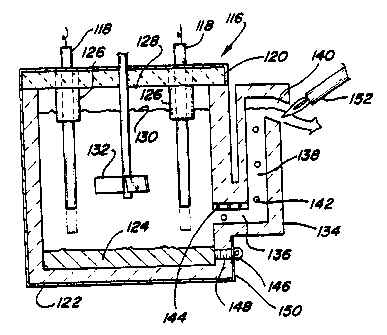
Referring now to FIGURE 16, a top down
electrode vessel 116 is shown. Electrodes 118 extend
through and are mounted in the cover 120 of the vessel
122. The top down melter 116 can be used to process a
glass melt in which metal precipitates tend to
accumulate in the bottom of the vessel 116. If
electrodes extend from the bottom of a vessel 32 and
metallic residue accumulates adjacent to the bases of
the electrodes a conduction path will be created between
electrodes through the accumulated metal residue 124.
Water cooled electrode holders 126 may be provided to
shield the electrodes from the atmosphere in the head
space 128 of the vessel above the level of the melt 130
and below the cover 120. If molybdenum electrodes 118
are used exposure to oxidizers in the head space 128
would result in unacceptable erosion of the electrodes
118. The water cooled electrode holders 126 shield the
molybdenum from erosion and extend slightly into the
glass melt. The glass melt 130 shields the electrodes
118 below the surface of the glass melt 130. An
impeller 132 is provided in the center of the melter
116. The impeller 132 shown in FIGURE 16 is a three
bladed impeller which mixes the glass melt 130 as it is
heated by the electrodes 118.
The glass melt is removed from the vessel
through a "teapot spout" 134. The teapot spout includes
a throat portion 136 which extends horizontally from a
lower portion of the vessel 122. A riser 138 extends
vertically from the throat 136 to the spout opening 140.
As the level of the glass melt 130 in the vessel 122
exceeds the level of the opening 140, the glass melt 130
overflows from the spout. A plurality of electrodes 142
CA 02105576 2001-10-22
71087-348
19
are provided in the throat 136 and riser 138 to keep the
glass melt 130 from blocking the teapot spout 134 which
would occur if the glass melt is permitted to cool. A
water cooled shield 144 is provided above the throat 136
to protect the vessel 122 in the region above the throat
136. A drain plug 146 is shown in a tab hole 148
adjacent to the base 150 of the vessel 122. Accumulated
metal residues of various waste streams may be
accumulated at the base of the vessel 122 and
periodically poured off through the tap hole 148 by
removal of the drain plug 146. By this technique heavy
phases, some of which may be valuable, may be removed
from the melter 116. A gas burner 152 is preferably
provided at the opening 140 to keep the glass freely
flowing as it enters the opening 140.
Referring now to FIGURE 17, another
alternative vessel 154 is shown wherein electrodes 156
extend through side walls 158 of the vessel. A drain
plug 160 is placed in a tap hole 162 adjacent to the
bottom 164 of the vessel 154. The impeller 166 is shown
aligned in height with the electrodes 156. It is
anticipated that the impeller may be raised or lowered
relative to the level of the electrodes 166. The tap
hole 164 is provided to allow draining of heavy phases
which may accumulate in the bottom 164 of the vessel
154. The impeller 166 mixes the glass melt 168 to
circulate the glass melt in the vessel 154 and thereby
distribute the heated portion of the glass melt.
Referring now to FIGURE 18, another
alternative is shown wherein a vessel 170 having
horizontally extending electrodes 172 extending from a
side wall 174 close to an adjacent side wall 176 of the
vessel 170. The horizontal electrodes 172 allow for
accumulation of metals in the bottom of the vessel 170
and present increased surface area as compared to the
side wall electrode embodiment of FIGURE 17. The
CA 02105576 2001-10-22
7108'1-348
impeller 178 is a shrouded impeller having a cylindrical
wall. The shrouded impeller minimizes voltage
differential fluctuations caused by rotation of the
impeller 178.
5 Referring now to FIGURE 19, an oxidation
reaction melter 180 is shown wherein a vessel 182 is
provided in which a glass melt 184 is mixed by an
impeller 186. The glass melt 184 is heated by side wall
electrodes. The electrodes shown are tin oxide
10 electrodes, or similar material, which is formed as
block shaped electrodes protruding only ,slightly from
the side walls 190 of the vessel 182.
Also shown in FIGURE 19 are oxidizer injector
tubes 192. Oxygen, air, steam or other oxidizers may be
15 supplied to the glass melt below the surface of the
glass melt 184. Oxygen added below the surface of the
glass melt 184 will react with constituents of the glass
melt 184 which are able to be oxidized. A water cooled
or oxidation resistant impeller 186 mixes the glass melt ,
20 184. In addition, oxidizer injected below the surface
of the glass melt 184 also causes vigorous mixing of the
glass melt 184. In some situations the impeller 186 may
be eliminated from the vessel 182 and mixing can be
caused solely by injection of the oxidizers or other
gases through the oxidizer injectors 192. A drain
opening 194 is shown in the base 196 of the vessel 182.
The opening 194 would be capped by a drain plug (not
shown) as previously described. The oxidation reaction
melter 180 could be used as a primary glass melter or it
could be used as a second stage in series with a
mixer/melter as previously described. The vessel 182
includes an inlet 196 through which molten glass is
received from a prior mixer/melter operation.
Alternatively, the inlet 196 could be used to receive
glass constituents, waste material for vitrification or
other feed stocks in a dry, slurry, or other form.
CA 02105576 2001-10-22
'1108'7-348
21
Referring now to FIGURE 20, an alternative
oxidation reaction vessel 198 is shown. The oxidation
reaction vessel 198 features an oxidizer injector 199
which is mounted in a base 200. The oxidizer injector
199 could be used in combination with an impeller or
various electrode combinations as previously described.
Alternatively, the oxidizer injector 199 could be used
in a conventional gas burner heated melter tank as a
second stage to a mixer/melter as described herein.
Referring now to FIGURE 21, a spinning disk
201 is shown which may be used in a second stage reactor
to direct a molten glass stream supplied to a second
stage reactor outwardly as glass filaments 202. For
example, carbon contaminants can be oxidized if an
oxidizing atmosphere is maintained above the glass melt
in the second stage reactor. The spinning disk 201
preferably has a plurality of ribs 203 to drive the
molten glass stream radially.
As shown in FIGURE 22, a rotating cup 204 can
be used to form glass filaments 205 in a second stage
vessel by pouring molten glass from a first vessel into
the rapidly rotating cup 204.
In FIGURE 23, an alternative embodiment is
shown which features a plurality of liquid metal
electrodes 206 located in the base 208 of the vessel
210. The vessel has an impeller 212 which stirs the
glass melt 216 while current is supplied to the liquid
metal electrodes 206 to heat the melt 216 above and
between the electrodes 206 by Joule effect heating.
Referring now to FIGURE 24, an alternative
glass melter 218 is shown wherein a plasma 220 directed
by heaters 221 at the surface of the glass melt 222.
Alternatively, the heaters 221 can be plasma, arc or
oxygen fuel burners which provide an intense energy
source. Intense heating of the glass melt,occurs at the
point where the plasma 220 impinges on the glass melt
CA 02105576 2001-10-22
71087-348.
22
222. This intensely heated portion of the glass melt
222 is intermixed with the remainder of the glass melt
by means of the impeller 226. The impeller 226 is a
shrouded impeller having upper and lower frustoconical
sections 228 and 230 flanking impeller blades 232.
Glass melt adjacent to the smaller opening of the
frustoconical sections 228 and 230 is driven by
centrifugal force towards the blades 232. The blades
232 expel the glass melt radially outwardly to create a
mixing flow in the melter 218.
The preceding embodiments of the present
invention are provided by way of example. The scope of
the present invention should be measured by reference to
the following claims.