Note: Descriptions are shown in the official language in which they were submitted.
W092/l6~0 PCT/US92/01904
210 '3 ~7~
--1--
DESCRIPTION
APPARATUS FOR IN-LTNE ANALY8I8
OF ~LO~ING LIQUID AND 80LID MATERIAL8
BY NUCLEAR MAGNE~IC RE80NANCE
TECHNICAL FIELD
This invention is related to the analysis of flowing
streams of liquids, solids or mixed liquids and solids by
nuclear magnetic resonance (NMR). In particular, it is an
apparatus that is small enough, economical enough and easy
enough to operate so that it is useful for making
measurements in applications such as the production of
foods and the like.
The analysis of materials using NMR requires a region
of space containing a magnetic field that is either
extremely uniform in magnetic flux density or else
extremely uniform in the spatial gradient of magnetic flux
density. In such a region, a sample to be analyzed is
subjected to a short pulse of electromagnetic energy at a
predetermined frequency that is a function of the ions to
be analyzed and of their chemical bonding. The pulse is
coupled to the sample by a surface coil. A typical pulse
duration is of the order of fifty microseco~ds, although
the pulse width that is chosen is a function of the
characteristic relaxation time of the material being
analyzed. The magnetic field causes the dipole moments of
the constituents of the sample to become aligned along
lines of magnetic flux. If the field is strong and
...... . . . . . . . .
. .. : - .. .. ~ . . :
. ~ .
W O 92/16040 PCT/US92/01904
7 8
uniform to a relatlvely high degree of precision, the
dipole moments will be essentially parallel to each
other. The electromagnetic energy coupled to the sample
changes the alignment of the magnetic dipoles in the
sample so as to align them with the net flux, which is the
vector sum of the originally applied magnetic field,
typically static, and the RF magnetic field associated
with the pulse. The relaxation of the dipoles from their
re-aligned position back to the original position when the
energy coupling is ended produces signals that can be
detected and analyzed to identify components of the sample.
Most NMR analysis to date has been done in large and
expensive installations that are typically sized to admit
a human subject into the region of controlled magnetic
fields. Such installations are usually sufficiently
complicated to require an operator or operators when the
installations are functioning. The result is a large and
expensive piece of equipment that is appropriate only for
use in a research laboratory or a hospital, and not in a
factory or industrial kitchen.
The production of certain foodstuffs would be aided by
the ability to use MMR analysis in a pipeline or other
such conduit to measure characteristics of flowing
liquids, pastes, slurries or solids in powdered or other
finely divided form. Continuous or continual analysis of
butterfat or cholesterol content would be useful in
- manufacturing and quality control of dairy products.
Fluids containing fats or oils could be analyzed to
control processes for manufacturing margarine and similar
substances. Doughs and other pasty materials which may be
dif~icult to analyze continuously by other means could be
analyzed in-line. These and other such uses, however,
require an NMR machine that is suitable for installation
and operation in a factory environment and that needs no
W092~t6~0 2 ~ O ~ 6 7 ~ PCT/US92/01904
more than routine operator attention. Such an NMR machine
would need one or more surface excitation and pickup coils
that are exposed to the flow of material that is to be
analyzed, and it would need a flow rate in a sampling area
S that was related to the relaxation time of the component
being tested.
The present invention overcomes the disadvantages of
the prior art by providing analysis of flowing streams of
liquids by nuclear magnetic resonance with an apparatus
that is small enough, economical enough and simple enough
to operate so that it is useful for making measurements in
applications such as the production of fruits and the like.
Where the flowable material is in a main conduit of a
first diameter, a sampling conduct of a second smaller
diameter is associated with the main conduit for
selectively receiving the flowable material to be
analyzed. An NMR device is coupled to the sampling
conduit for subjecting the flowable material to the
necessary magnetic fields to generate NMR signals and to
receive the generated NMR signals for analyzing the
flowable materials. A first selectively closable valve is
placed in the main conduit for diverting the flowable
material to the sampling conduit. If desired, at least
one selectively closable valve is placed in the sampling
conduit on one side of the coupled NMR device to allow the
diverted material to enter the portion of the sampling
conduit in the fixed magnetic field for analysis by the
NMR device. In one embodiment, the NMR sampling coil is
simply wrapped around the sampling conduit for providing
the NMR analysis. In another embodiment, the sampling
conduit is mounted within the main conduit for receiving a
f~owable material. The sampling conduit is mounted in the
main conduit in a fixed magnetic field such that at least
a portion of the sampling conduit is within the magnetic
, ~ -, : -. . - - , .
. .
,
WO92/16~0 PCT/US92/01904
' 1~J5~
field. The sampling conduit is mounted in the main
cc~nduit with a non-metallic, non-magnetic base member
coupling the main conduit and the sampling conduit for
holding the sampling conduit centered within and parallel
to the main conduit. The base member is elongated in the
direction of material flow and has a shape such as an
ovate cross-section to reduce resistance to the material
flow in the main conduit. A coil encircles the flowable
material in the sampling conduit with its elongated axis
parallel to the direction of the material flow so as to
cause a concentrated magnetic field in the flowable
material within the sampling conduit. Electrical
conductors are embedded in the base and couple the coil to
the NMR device for enabling the flowable material to be
subjected to the NMR pulse energy and for coupling the
generated NMR signals to the NMR device.
In another embodiment, the coil is mounted in the
sampling conduit with its elongated axis perpendicular to
the material flow. A non-metallic, non-magnetic elongated
support for the coil allows the flowable material in the
sampling conduit to be sufficiently close to one side of
the coil to be excited by the RF pulsed energy and
sufficiently far from the other side of the coil to be
substantially unaffected by the RF pulsed energy so as to
minimize the generation of NMR signals of opposite phase.
The mounting device for the coil comprises a non-magnetic,
non-metallic elongated support for the coil extending
p~rpendicular to the longitudinal axis of the sampling
tube for supporting the coil adjacent to the flow of
material in the sampling tube. A non-metallic,
non-magnetic base is attached to the support and the
sampling conduit such that the material flows sufficiently
close to only one side of the coil on the elongated
support to be excited by the RF pulsed energy and on each
. : .
W092/16~0 PCT/~S92/01904
21~7~
side of the base sufficiently far from the coil to be
substantially unaffected by the RF pulsed energy. Thus
the base is in the general shape of a T having arcuate
surfaces connecting each end of the horizontal arm of the
T to the base of the T, the horizontal portion of the T
being attached to the elongated support and the base of
the T being attached to the sampling conduit. Both the
elongated support and the base have a shape, such as an
ovate cross-section, to reduce resistance to material flow
in the sampling conduit.
In another embodiment, the sampling conduit of a
second smaller diameter is associated with the main
conduit of a larger diameter for selectively receiving the
mat~rial. A test conduit is rotatably coupled to the
sampling conduit for receiving the material. An NMR
device is coupled to the test conduit for subjecting the
flowable material therein to a fixed and a variable
magnetic field to generate MMR signals and receive the NMR
signals for analysis of the flowable material. The test
conduit is rotatable with the material flowing therein
during subjection of the material to the fixed and
variable magnetic fields to correct for irregularities in
the magnetic fields.
Thus, it is an object of the present invention to
provide an apparatus for performing NMR analysis on
flowing materials.
It is a further object of the present invention to
provide an apparatus for measurement of characteristics of
flowing materials in a factory environment using NMR.
It is yet another object of the present invention to
provide an apparatus for making NMR measurements on
liquids that are flowing in a conduit.
It is still another object of the present invention to
provide an apparatus for NMR measurements on divided solid
materials that are flowing in a conduit.
. . .
,,~ :- - . , . .... - .
- , ~
W O 92/16040 PC~r/US92/01904
2la~
It is also an object of the present invention to
provide an apparatus for continual sampling of materials
Xrom a flowing stream of materials in a conduit and
testing properties of those materials by NMR analysis.
Other objects will become apparent in the course of a
detailed description of the invention.
8Cn~M2~RY OF T~E INrVEN~ION
An apparatus for performing on-line NMR analysis of
flowing fluids including liquids, slurries, pastes and
divided solids includes a surface pickup coil that is
disposed in or near the fluid to make measuring contact
with the fluid in a main conduit in which the fluid is
flowing or in a sampling conduit in which the fluid either
is flowing or is stationary but has recently been
flowing. The region containing the surface coil is
subjected to an extremely uniform static magnetic field.
The surface pickup coil or a similar coil used only for
excitation is excited with a pulse of RF electric current
of a predetermined frequency and time duration to align
precession axes of magnetic dipoles of selected materials
in the fluid, and the surface pickup coil then detects
signals from relaxation of the dipoles to their original
positions. These signals are associated with the selected
materials in the fluid and can be interpreted to identify
these materials and to measure quantities of these
materials in the flowing streams from which they were
sampled. To do so, the signals are taken to an NMR
analyzer which processes them to obtain a free-ion decay
curve, a decay spectrum, or both. The sampling conduit
may be coupled to the main conduit to selectively receive
material diverted from the main conduit. In another
embodiment, the sampling conduit may be centered in the
.- , ,
:
'' ~ : . ~ .'
'- ' " '' .~ '' ' ' .
WO92/16040 PCT/US92/01904
21~678
-7-
main conduit along and parallel to the main conduit
elongated axis. In such cases, the coil may be wound
around the test tube with its elongated axis parallel to
the axis of the test tube or with its axis perpendicular
to the axis of the test tube. In still another
embodiment, the test tube is rotatable while analyzing a
sample in a sample conduit so that the process is a
continuous analysis of the flowable materials.
BRIEF DESCRIPTION OF THE DRAWINGS
These and other objects of the present invention will
be more fully understood in conjunction with the
accompanying drawings in which like numbers indicate like
lS components and in which:
FIG. l is a diagrammatic representation of an
apparatus for the practice of the present invention;
FIG. 2 is a functional block diagram of a portion
of the apparatus of FIG. l;
FIG. 3A is a view of an embodiment of a surface
pickup coil to be used in the apparatus of FIG. l;
FIG. 3B is a cross-sectional view of the device
in FIG. 3A illustrating the concentration of the
magnetic field in the center of the conduit carrying
the sample under test;
FIG. 4A is a sectional view of an alternate
embodiment of an apparatus for the practice of the
present invention;
FIG. 4B is a top view of the device in FIG. 4A;
FIG. 4C is a side view of the device in FIG. 4A;
:
.. :
WO92/16~0 PCT/US92/0~904
5 ~
FIG. 5A is a perspPctive view of a second
alternate embodiment of an apparatus for the practice
of the present invention;
FIG. 5B is a side view of the device of FIG. 5A;
FIG. 5C is a top view of the device of FIG. 5A;
and
FIG. 6 is a diagrammatic representation of a flow
through in-line NMR device.
10 D13TAII.ED DE8CRIPTION
FIG. 1 is a diagrammatic representation of an
apparatus for the practice of the present invention. In
FIG. 1, a main conduit 10 carries a flow of liquid, paste,
slurry or divided solid through a valve 12 in the
direction of an arrow 14. The valve 12 is optional, but
it may be useful in directing flow through a sampling
conduit 16 and controllable valves 18 and 19 in the
direction of an arrow 20. The sampling conduit 16 has at
least a portion 17 thereof that is placed in a magnetic
field and that is conveniently sized to fit a surface coil
22 which is connected to an NMR apparatus 24. The conduit
portion 17 may be formed of any nonconductive material
such as plastic. The sampling conduit portion 17 can be
sized to fit surface coil 22 without putting a limit on
the size of the main conduit 10 and hence on the~quantity
of material that flows in the main conduit 10. The
positioning of the sampling conduit 16 and the valves 18
and 19 makes it possible to control the flow rate in the
sampling conduit 16 and hence, the flow through the
conduit portion 17 surrounded by surface coil 22. They
also make it possible to take a sample and hold it
stationary during a period of analysis, which typically
takes in the order of seconds to gather data. The NMR
: - . -. . :
.
: -
~ - -: : .
.. . ~ .. . . . .. ... .
WO92/16~0 PCT/US92/01904
2~0~67~
apparatus 24 controls the operation of valves 12, 18 and
l9 and also analyzes the sample in conduit 16.
FIG. 2 is a functional block diagram of the surface
coil 22 and NMR apparatus 24 of FIG. l. In FIG. 2, the
surface coil 22 is disposed in a magnetic field generated
by magnet 2l and encloses a flowing sample of material in
conduit 17 that is to be analyzed by NMR techniques. The
surface coil 22 is connected to the NMR apparatus 24,
which is controlled by a microprocessor 30. A signal from
the microprocessor 30 gates an RF generator 32 that
applies pulsed electromagnetic energy to the flowing ~-
sample in conduit portion 17 through the surface coil 22.
After the RF generator 32 is gated off by the
microprocessor 30, detected NMR signals are taken on line
33 to an amplifier 34 that is connected to an
analog-to-digital (A/D) converter 36. In converter 36 the
NMR signals are digitized for connection to the
microprocessor 30 as is well-known in the art. The
microprocessor 30 is connected to the memory 38 and a
display 40 and may be programmed or controlled by a
program 42. The operation of the NMR apparatus 24 is
described in more detail in U.S. Patent No. 4,875,486,
which is assigned to the assignee of the present invention
and which is incorporated here by reference as if set
forth fully. Operation of the NMR apparatus 24 is also
facilitated by using as the amplifier 34 a true log
amplifier as disclosed in pending U.S. Patent Application
Serial No. 403,089, which is also assigned to the assignee
of the present invention and which is incorporated here by
reference as if set forth fully.
It is well known in NMR analysis that particular
compounds that are subjected to a static magnetic field
tend to have dipole moments aligned with the magnetic
field. The application of a p~lse of electromagnetic
W O 92/16n40 ~ 1 0 5 ~ 7 ~ PC~r/US92/01904
--10--
energy which sets up a magnetic field in a direction
di.fferent from the direction of the static field changes
the alignment of these dipoles to that of the resultant
magnetic field. When the pulse is then turned off, the
relaxation of the dipoles to their original alignment with
the static magnetic field produces signals that can be
detected and analyzed for the presence of components in
the compound having the particular dipole moments in
question.
The application of NMR analysis to measure
characteristics of flowing materials requires either that
the relaxation of dipoles be substantially complete while
the excited flowing material is within range of the
surface coil that has excited the dipoles, or else that
more than one surface coil be used. The choice between
using one coil and using more than one is determined
p~imarily by the answer to the question whether relaxation
will be substantially complete while the sample is still
within the detection range of one coil. If it will not
be, then two coils will be needed. In either case, the
procedure is well known in the art.
FIG. 3A is a view of a pickup coil to be used in one
embodiment of the apparatus of FIG. 1. In FIG. 3A, the
conduit section 17 has flowing therein the material to be
analyzed. The coil 22 is wrapped around the conduit 17
with one or more turns as needed to generate RF pulses for
exciting the material in conduit 17 and also for picking
up the NMR signals that are coupled on lines 52 to the NMR
device 34. The coil can be wound about the outside of
conduit 17 because it causes a strong magnetic field on
the inside of conduit 17 and a weak magnetic field on the
outside of conduit 17. This can be seen more clearly in
FIG. 3B which is a cross-sectional view of the conduit 17
in FIG. 3A. In FIG. 3B, it can be seen that the coil 22
.
. ,
W092t16040 PCT/US92/01904
210~678
is wound around the outside of the conduit 17. It will be
noted that the flux lines 44 all converge on the inside of
conduit 17. Thus, there is a strong magnetic field on the
inside of conduit 17 and a weak magnetic field on the
outside thereof. The NMR signals generated by the nuclei
of the material under test is detected by coil 22 and
coupled on lines 52 to the NMR device 24. In FIG. 3A,
~ecause the coil 22 is wound about the outside of conduit
section 17, it is possible to rotate conduit 17 for
providing a more accurate reading as described in
copending application Serial No. 666,576, filed
March 8, 1991, owned by same applicant and incorporated ~ .
herein in its entirety by reference. Thus, the embodiment
illustrated in FIG. 3A allows the sampled material to be
non-rotating within the magnetic field or rotated by the
~otation of conduit 17.
FIG. 4A is a cross-sectional view of an alternate
embodiment of a device for sampling a continuously moving
f luid in a conduit. In the cross-sectional view
illustrated in FIG. 4A, it can be seen that a small
internal conduit 46 is mounted on the inside of sampling
conduit 17 at the center thereof with a mount 58. Conduit
17 could, of course, be the main conduit and smaller
conduit 46 could be called the sampling conduit. The
mount 58 is shaped in the elongated direction as an oval,
as can be seen best in FIG. 4C. The oval shape allows
fluid to pass thereby unimpeded or at least with a minimum
of flow resistance. A coil 48 is wrapped around internal
conduit 46 and has its output leads 54 and 56 passing
through the mount 58 to the outside of the conduit 17
where they can be coupled to the NMR device 24 illustrated
in FIGS. 1 and 2. Thus, as the material f lows into
conduit 17 in the direction of arrow 50, a portion of the
fluid follows the direction of arrow 51 înto the internal
'
WO92/16~0 PCT/US92/01904
~11)5~
-12-
conduit 46 where it can be analyzed by typical NMR
methods. FIG. 4B is a top view of the device illustrated
in FIG. 4A and illustrates the minimum interference with
fluid flow by the mount 58 and illustrates the
relationship of the coil 48, the internal conduit 46 and
the mounting bracket 58. Thus, the device shown in
FIGS. 4A, 4B and 4C can be utilized for a stationary
conduit 17 to be used to take NMR measurements of a
sample. It cannot be used where it is desired to rotate
the tube or conduit 17.
FIGS. 5A, 5B and 5C illustrate a second alternate
embodiment of a conduit which contains a coil for
providing signals to an NMR device. FIG. 5A is a side
view of an alternate device for mounting the coil in the
conduit 17. In FIG. 5A the coil is mounted in the tube
such that its axis is perpendicular to the flow of the
fluid. In such case, the coil 62 is positioned in a
mounting bracket 60 to shield the coil 62 from the
fluids. It may be made similar to mount 58 in Fig. 4A, 4B
a~d 4C of glass, plastic and other nonmagnetic and
nonmetallic materials. In such case, it is not desirable
to allow the fluid to pass on either side of the coil 62
equidistant from the coil. The reason is that the flux
lines 66, as shown in FIG. 5B, concentrate in density near
the center of the coil 62. Because the flux enters one
side of the coil and exits the other, a reverse polarity
is encountered when NM~ signals from the material on
either side of the coil are detected. They are of
opposite phase. Therefore, it is desirable that the
material interact with coil 62 on only one side thereof.
Thus, the coil 62 is mounted on the side of mounting
bracket 60 away from the mounting base 64 as shown in
FIG. 5B. The distance from the front 68 of the mounting
bracket 60 to the coil 62 is very small, thus allowing
.
. ,
:
WO 92/16040 PCI/US92~0t904
2103678
free interaction of the fluid in the heavy density
magnetic field lines 66. However, the back distance from
coil 62 to the outside 64 of mounting bracket 60 is
considerably larger and thus, as illustrated in FIG. 5C,
5 the lines of flux are already breaking up in those areas
and thus are much less dense. Consequently, there is less
interaction between the nuclei of the materials in flow
through areas designated by the numeral 50 on each outside
64 of base 60 than there is in the area 50 in front of
10 side 68 of mounting bracket 60. Again, mounting bracket
60 is formed with an oval cross section in the vertical
direction as illustrated in FIG. 5B to allow the fluid
entering conduit 17 in the direction of arrow 50 to pass
freely over the mounting brac~cet 60. In like manner, the
15 portion of mounting bracket 60 including outside 64 is
also oval shaped in cross section so as to allow a free
fluid flow in the passages 50 on either side thereof.
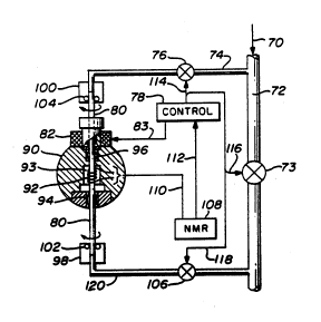
FIG. 6 is a diagrammatic representation of a flow
through in-line NMR apparatus which can perform N~ tests
20 with a rotating test tube. In FIG. 6, the incoming fluid
70 passes through conduit 72 and valve 73 to some
production facility where the fluid would be utilized.
The fluid may be of the type referred to previously which
requires periodic analysis and testing. In such case, a
25 sampling conduit 74 diverts some of the fluid through a
closable valve 76 to a rotating test tube 80. The manner
in which test tube 80 is rotated is disclosed in detail in
copending application Serial No. 666,576, filed March 8,
1991, owned by same applicant and which is incorporated
30 herein by reference in its entirety. Generally speaking
however, a motor 82 drives a hollow shaft 85 to which the
test tube 80 is frictionally coupled. ~he motor 82 is
controlled by signals on line 83 from a control unit 78
which may be a program. The test tube passes through a
,
' ' .
.
. .
WO92/16040 PCT/US92/01904
210~673
-14-
cavity 93 in a magnet 90 with a coil 92 located in the
c:avity 93. Self-lubricating bearings 94 and 96 support
the test tube 80 for rotation. Coupling units 98 and 100
have self-lubricating seals such as Teflon seals 102 and
104 to prevent fluid leakage in the coupling units 98 and
100. Valve 106 in output line 120 may be opened and
closed as needed to subject the sample to the NMR
testing. An NMR device 108 is coupled on line 110 to the
coil 92 in cavity 93 to pulse the coil and to detect the
NMR signals generated by the material under test. The NMR
device 108 includes a computer which communicates with the
program 78 to control valves 73 with signals on line 116,
76 with signals on line 114 and 106 with signals on line
118. It also controls the speed of the motor 82 with the
signals on lines 83 to rotate the test tube 80 at the
desired speed. With valves 76 and 106 open and valve 73
closed, a continual flow of fluid through test tube 80 can
occur, thus having the NMR testing occur as the material
is passing through the sampling conduit 74. Clearly, it
would not be necessary to rotate test tube 80 in the
schematic representation illustrated in FIG. 6. If more
accurate readings are required, then the test tube can be
rotated as indicated.
Thus, there has been disclosed a novel system for
analysis of flowing streams of liquids, solids or mixed
liquids and solids by nuclear magnetic resonance. The
pulsing and detecting coil can be wrapped around the
outside of a conduit carrying the fluid, it can be wrapped
around a conduit within a larger conduit that is carrying
the fluid, it may be positioned with its axis
perpendicular to the fluid flow with the fluid in
operative relationship with only one side of the coil to
reduce errors and includes a flow through system in which
the test tube may be rotatably located in a magnetic field
to provide more accurate analysis of the sample under test.
, : - . . ..
" . , . : :
: . . -
.
WO92/16040 PCT/US92/01904
210~73
-15-
The foregoing specification describes only the
embodiments of the invention shown and/or described.
Other embodiments may be articulated as well. The terms
and expressions used, therefore, serve only to describe
the invention by example and not to limit the invention.
It is expected that others will perceive differences
which, while different from the foregoing, do not depart
from the scope of the invention herein described and
claimed. In particular, any of the specific
constructional elements described may be replaced by any
other known element having equivalent function.