Note: Descriptions are shown in the official language in which they were submitted.
WO 92/17822 PCT/i_1592/01106
FILL CONSTRUCTION FOR USE IN A PLAIN PAPER COPIER
Backaround of t:he Invention
Field of the Invention
This invention relates to eleci~rography, and a method of
development, transfer and fixing of dried toner
to electrographic images. Specifically, it relates to such
images for use in overhead projectors, especially to
color images for use therein.
Description of the Related Art
Electrography refers to the processes of
electrophotography, electroradiography, and
magnetography. The process of electrography has been
described in numerous patents, such as U.S.Patent Nos.
2,221,776, 2,297,691, and 2,357,809; (Carlson). The
process, as taught in these and other patents,
essentially comprises production of a latent
electrostatic image using photoconductive media and the
subsequent development and transfer of a visible image
therefrom. A latent electrostatic image may also be
formed by spraying the charge onto a suitable charge-
retaining surface as taught, for example, in U.S. Patent
Nos. 2,143,214, 3,773,417, and 3,017,560. In
magnetography, the latent image is magnetic and maybe
developed with appropriately magnetized or magnetizable
3o developer particles, as described in U.S. Patent No.
3,520,811.
Development of the latent image can be accomplished
by deposition of developer particles on the electrostatic
or magnetic latent image, the most common technique using
powder, cascade, or less frequently, liquid developers.
It is well kmown in the art to use dry powder toner
to develop a latent electrostatic image. U.S. Patent No.
2,855,324 discloses thermoplastic coated receptors to
which a dry toner image may be transferred by contact
WO 92/17822 rcrius~zio> >o~
~~~~ ~ ~'~ ~
_2-
under pressure. U.S. Patent No.. 3,640,749 discloses
coating a transferred dry powder image and receptor with
a dispersion of a synthetic resin in water. U.S. Patent
No. 4,071,362 discloses use of a receptive styrene-type
resin on a thermally resistant base film to~fuse with
thermoplastic coated dry toner particles (i.e., image-
fixing is achieved by use of a special toner). U.S.
Patent No. 3,620,726 discloses the use of pigment
developer of particle size within the range of 5.0 to
10.0 microns, with not more than 50% of the particles
being of less than 1 micron equivalent spherical
diameter, thereby reducing background stain. As
mentioned, this type of transfer may result in problems
of durability.
To avoid such durability problems, various
liquid developers have been employed as disclosed in U.S.
Patent 4,337,303, (Sahyun et al.). The liquid toner is
encapsulated into a homogeneous continuum of particles
within the soft or softened receptor coating. At least
750 of the transferred particles must be embedded within
the surface such that they do not protrude.
Particles have also been used in transparencies.
U.S. Patent No. 4,869,955, (Ashcraft et al.) discloses a
transparency comprising a polyester support, and at least
one toner receptor layer comprising a mixture of an
acrylate binder, a polymeric antistatic agent having
carboxylic acid groups, a crosslinking agent, and two
types of beads, i.e., a butylmethacrylate modified
polymethacrylate bead and submicron polyethylene or
tetrafluoroethylene beads. The smaller beads are
disclosed to improve scratch resistance, and have a
particle size of less than one micron, while the
polymethacrylate beads are disclosed to assist in
transport of the film through the copier and have a
particle size of from about 1 to about 5 microns in size.
Where full color images are desired, additional
considerations are required. Frequently the prior art
WO 92/17822 w ~-t PCT/~JS92/01106
2~.~~"~ a ~
-3-
processes using dry developing methods showed bright,
full color images when the film was inspected, but showed
an overall gray tone when the image was ;_ojected. As a
result the color-tone reproduction range was very narrow.
European Patent Application 0349,227, discloses a
transparent laminate film for :full color image forming
comprising two transparent resin layers. The first resin
layer is heat-resistant, and the second resin layer must
be compatible with a binder resin constituting the toner
to be used for color image formation. The second resin
layer must have a larger elasticity than that of the
binder resin of the toner at a fixing temperature of the
toner, preferably in the range of 5 to 1000 times larger
than such binder elasticity. While it is stated at page
5, lines 8-26, that resins of the same '°kind" , i.e.,
type, e.g., styrene-type or polyester-type, may be used
as the toner binder~and the second transparent resin
layer, the resins must still differ in storage elasticity
modulus as previously stated.
It is further specifically stated at page 7, lines
9-14, that where the melt viscosity of the second layer
becomes lower than the viscosity of the toner binder
resin, it is difficult to develop good color mixing.
It has now been discovered that a good image, even a
good full-color image is provided by an electrographic
article having a polymeric receptor layer wherein the.
storage elasticity modulus is equivalent to, or less than
that of the toner resin.
It has also been discovered that using polymeric,
silica or starch particles in transparent electrographic
articles creates a sufficient gap between the film and
smooth surfaces with which it contacts that transfer of
fuser oil to the projector glass and pooling of fuser oil
between the article and a protective sleeve is reduced or
eliminated.
WO 92/17822 PCT/U592/01106
~~ ~ j,.~.~ ~ _
Summary of the Invention
The present invention provides an electrographic
article comprising a polymeric film having at least one
polymeric receptor layer coated on at least one side
thereof, said receptor layer having an equivalent or
lower storage elasticity modulus than a toner resin used
for forming images on said article.
Preferable articles of the invention comprise a
polymeric receptor layer having a storage elasticity
l0 modulus about equivalent to the toner resin.
one specific embodiment of the invention provides an
electrographic article capable of providing a good full
color image when the image is projected.
One preferred embodiment of the invention further
comprises polymeric or starch particles, at least 50% of
such particles protruding from the polymeric receptor
layer, preferably at least 75%, prior to imaging with a
toner. Preferably, when starch particles are used,
particles are present in an amount such that distribution
in the polymeric receptor layer is greater than about 2
particles/mmz. The particles have an average particle
size of at least about 5 ~,m. When polymeric particles,
e.g., polymethylmethacrylate (PMMA), polystyrene, and the
like are used, particles are present in an amount such
that distribution in the polymeric receptor layer is
greater than about 5 particles/mm2. These particles also
have an average particle size of at least about 5 ~,m.
Yet another preferred embodiment of the invention
provides an electrographic article having attached
releasably thereto an overlay, at least a portion of such
overlay being opaque. The overlay is preferably a porous
sheet which reduces fuser problems due to elasticity of
the porous sheet. It also minimizes slippage of the film
in the fuser, in xerographic machinery, and by reducing
the maximum temperature of the film, fuser exit.creasing
is decreased.
WO 92/1722 pCT/US92/01106
2 ~. 0 ~:~'~ '7 '~
-5-
The following terms have these meanings when used
herein.
The term "transparency" means a transparent
electrographic article carrying a toner image suitable
for projection on an overhead projector.
2. The terms "copier", "copying machine" are used
interchangeably to refer to any electrographic or
xerographic apparatus which is capable of forming an
image on an article of the invention.
3. The terms "envelope", "sleeve" and "cover" are
used interchangeably to refer to a protective article for
a transparency, typically consisting of a pocket of
transparent plastic sheet material open along at least
one side edge for insertion of the transparency.
As used herein, all parts, percents, and ratios are
by weight unless specifically otherwise defined.
Brief Description of the Drawings
Figure 1 shows an electrographic article having an
overlay consisting of a sensing stripe.
Figure 2 shows an electrographic article having an
opaque overlay consisting of a sensing stripe and a tab.
Figure 3 shows an electrographic article having an
opaque overlay consisting of a single opaque sheet having
one or more transparent windows.
Detailed Description of the Invention
Polymeric film layers useful as a substrate in
electrographic articles of the invention include heat-
3o resistant films such as polyester, e.g., polyethylene
terephthalate, polymethyl-methacrylate, cellulose
triacetate, polyethylene, polystyrene film,
polyvinylidene fluoride, polyvinyl chloride, such as
polyamides, and polyimides. Preferred film layers
include polyethylene terephthalate. Such films are
widely commercially available from such companies as
Minnesota Mining and Manufacturing (3M), ICI and F.I.
DuPont de Nemours (DuPont).
w0 92!1782= PCT/US92/01106
r ~ -,
The substrate should preferably have a thickness of
from about 50 ~C to about 150 ~,.
Useful polymeric receptor layers include
thermoplastic resins such as po7.yester resins, styrene
resins, polymethylmethacrylate resins, epoxy resins,
polyurethane resins, vinyl chloride resins, and vinyl
chloride-vinyl acetate resins.
Preferred receptor layers include polyester resins,
e.g., polyesters based on bisphenol A, such as
AThAC~'382E, (also sold as ATLAS'"R 32-629), available from
Reichold Chemical as well as bisphenol A monomers and
their derivatives, (e.g., the dipropylene glycol ether of
bisphenol A). A suitable carrier binder such as Vitel PE
222 polyester resin, available from The Goodyear Tire and
Rubber Company, is also present when bisphenol A monomers
or their derivatives are used to facilitate coating. The
thickness of the receptor is preferably between about 0.5
to about 10 ~.m, more preferably from about 1 to about 6.5
um.
l4hen full color images are made in the
electrographic apparatus, the color image is developed,
then finished or "fixed". The fixing device involves the
use of heated rollers which are coated with a silicone
oil to prevent smearing of the images, and to provide
easy release of the image from the roller's surface.
Images on transparencies require much more effective
coalescence of toner particles than images an paper
because the transparency image is projected. Therefore,
a longer residence time is usually needed in the fixing
device in order to fix the image. During this residence
time, the fuser deposits much more oil onto the surfaces
of the film than would be deposited during the shorter
residence time of paper being imaged. This oil gives the
transparency an objectionable sensation to the touch.
Further, while the~oil does not seem to have a
detrimental effect on the image when projected, it is
transferred onto the projector stage, where if transfers
WO 92/17822
1 ~ J ~ ~ ~~ p~/US92/01106
onto subsequently used transparencies, as well as the
hands and possibly clothing of the presenter.
Transparencies are frequently inserted for use into
an envelope or cover, e.g., those disclosed in U.S.
Patent 4,402,585, (Gardlund). These envelopes comprise a
rectangular pocket formed of transparent sheet material
defining opposed rectangular faces which are separable at
least along one side edge for insertion of a transparency
therebetween. They are commercially available from the
3M Company under the trademark Flip-Frame'. The envelope
provides convenient usage, and notebook storage.
Further, it protects the transparency image from damage
caused by distortion of the film, creasing, scratching,
smearing, tearing, and the like. This is especially
important with full color transparencies, which are
expensive. However, the use of the envelope provides a
further problem when a large amount of fuser oil is
present.
The oil migrates to the regions where the
transparency touches the sleeve, forming visible pools as
large as several centimeters. When projected, the edges
of the pools are visible and quite objectionable.
It has been found that adding certain polymeric,
silica or starch particles reduces the pooling of the oil
at the edges of the sleeves and inhibits transfer of the
oil to projection stages.
Useful polymeric particles include, but are not
limited to, polymethacrylate, and modified
polymethacrylate particles such as polybutylmethacrylate,
polymethylmethacrylates, hydroxyethymethacrylate, and
mixtures or copolymers thereof, polystyrene,
polyethylene, and the like. It is preferred to make such
particles as a dispersion to obtain uniformity of size,
and shape, and to crosslink the particles to promote
nonaggregation. Preferred polymeric particles range in
size from about 5 ~Sm to about 25 um, and are present in
amounts of greater than 5 particles/mm2. At the larger
end, the particles may be somewhat visible; however they
wo 92i»sz? i'CT/US92/U11~6
__
_8_
do not affect the fusing or the quality of the image.
Useful starch particles are from about 5 to about 25
~m in diameter, more preferably from about 10 to about 20
~Cm in diameter. Larger particles are effective to reduce
the oil pooling, but have the problem of being visible
when projected. Smaller particles, i.e., less that 5 ~cm,
in diameter may be used, but a higher loading is required
to effectively reduce the oil pooling. This often results
in higher haze of the final image. Also, the smaller
particles are not effective in regions of the
transparency where the thickness of the toner layer
exceeds the extent to which the particles normally
protrude from the receptor layer. This is especially
important when multiple toner layers are present, e.g.,
in color electrophotography. For example, after fusing a
two layer green (cyan plus yellow) toner layer on a Canon
"CLC 200", the toner thickness can be from about 3.5 to _
about 11 Vim.
Preferred starch particles include "LOKSIZE 30"
starch particles, available from A.E. Staley Company..
Surprisingly such large particles do not affect the
quality of the image when used in the required amounts.
It is especially surprising that such particles, when
properly chosen, do not interfere with the fusing of the
images.
In another specific embodiment of the invention, the
article has an overlay attached thereto, at least a
portion of which is an opaque sensing stripe. The stripe
is typically 5-15 mm in width, and is adhered along and
in register with the leading edge of the transparent
sheet. The purpose of the overlay is to signal the
copying machine that a transparency has been fed therein.
The copier then reduces the fuser speed to increase the
fusing time. Without the opaque overlay, a transparency
cannot be seen by the copier. If the width of the
overlay exceeds about 20 mm, the film is treated
identically to a piece of paper, with no reduction in
fuser speed.
WO 92/17822 ~ ~, ~ ~ ~ PCf/US92/01106
-g-
Preferably, such an article further comprises a
second opaque region, or "tab"; preferably made from an
opaque porous sheet, e.g., a porous polymeric or paper
sheet. This second opaque region underlies the
transparent sheet, and is spaced from the first opaque
. stripe, leaving a transparent window of from about 5 mm
to about 15 mm in width.
This opaque tab can be bonded to the transparent
sheet by a repositionable adhesive composition. Such
l0 compositions are well known in the art, especially
preferred are those particulate adhesives disclosed in
U.S. 3,691,140, (Silver et al.). These repositionable
adhesives are infusible, solvent-dispersible, solvent-
insoluble, inherently tacky, elastomeric copolymer
microspheres consisting essentially of about 90 percent
to about 99.5 percent by weight of at least one alkyl
acrylate ester and about 10 to about: 0.5 percent by
weight of at lest one monomer selected from the group
consisting of substantially oil-insoluebl;, water-soluble,
ionic monomers and malefic anhydride.. The microspheres
. are prepared by aqueous suspension polymerization
utilizing emulsifier in an amount greater than the
critical micelle concentration. Also useful are such
repositionable adhesives as dispersions of crosslinked
rubbers or acrylates.
The use of such an opaque tab reduces processing
problems in the fuser area of the copier due to the
elasticity of the porous sheet. It minimizes slippage of
the film in the fuser, and by reducing the maximum
temperature of the film, fuser exit creasing is
decreased.
Also, the tab absorbs all of t:he silicone oil
present on the back of the film and therefore eliminates
the coating of starch particles on the underside of the
transparency film. Finally, the image may be immediately
previewed against an opaque background.
An alternative construction for the overlay involves
the use of a single opaque sheet to constitute both the
WO 92117822 pC't'/bg92/07106
sensing stripe and the tab. The leading edge is in
register with the leading edge of the transparent sheet.
However, the sheet has one or more transparent windows,
parallel to both short and~long edges of the
transparency, and placed at least about 5 to about 15 mm
from the edge. The length of the window must be
sufficient to reliably trip the sensor on the copier,
preferably at least about 40 mm. To allow the film to
work in machines having differing sensor locations, the
length of the windows may be extended to as much as about
75% of the length of the edge to which they are parallel.
Such windows may be die-cut or formed by any conventional
means, and are from about 5 mm to about 15 mm in width.
The windows allow the article to be f.ed with either edge
as the leading edge, as well as facilitating easier
processing due to the use of a single sheet.
Detailed Description of the Drawings
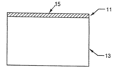
In Figure 1 an opaque sensing stripe, 11 is
2o releasably attached to the transparent sheet 13 in line
with the leading edge 15.
In Figure 2, an opaque sensing stripe, 11, is
releasably attached to a transparent sheet in line with
the leading edge, 15. A tab, 17, also releasably
attached, is separated from the sensing stripe by a
transparent window, 19, parallel to the leading edge.
In Figure 3, the overlay comprises a single opaque
sheet, 21, adhered releasably along, and in register with
the leading edge, 15 of the transparent sheet. The
overlay has two die-cut transparent windows, 19. One of
the die-cut windows, 19, is parallel to the long edge,
15, and one window, 19, is parallel to the short edge,
23, of the transparency, which allows the transparency to
be rotated so that the short edge, 23, can then be used
as the leading edge, if desired.
WO 92/17822 PCT/US92l01106
~~~j~~~
-11-
Test Methods
Haze Test
Haze is measured with the Gardner Model XL-211
Hazeguard hazemeter or equivalent instrument. The
procedure is set forth in ASTM D 1003-61 (Reapproved
1977). This procedure measures haze of the unprocessed
film.
Image Transparency
Image transparency or "Pastel Haze" measures how
l0 much light is scattered by a fused toner layer. Higher
quality images have lower pastel haze values. The haze of
a yellow halftone was measured using a Gardner Model XL-
211 Hazeguard hazemeter. First, the machine is zeroed
with no film in place, the Reference/Open switch set to
"Open". Next, the film is placed at the entrance port,
and set the switch to "Reference" and record the reading.
Again set the Ref/Open switch to "Open" and record
reading. The percent Haze is computed according to the
following formula.
% Haze = (Open Reading x 100%)
Reference Reading
Color Reproduction Oualit
Color reproduction quality was measured using a
Gardner Spectroguard Color System, a single beam
spectrophotometer using a halogen lamp filtered to
simulate CIE D65. This instrument was selected for its
large aperture, higher accuracy, and ability to
quantitatively measure color reproduction accuracy. L°a'b'
was measured in transmission mode using a viewing angle
2° from normal.
The L'a'b° color space is a quantitative, three-
dimensional description of color; the three axes L°, a',
and b' represent independent aspects of a particular
color. The L' axis measures, the white to black level,
with increasing values approaching white. The a° axis
measures green to red levels of color, with more negative
WO 92/17822 PCT/US92/01106
-12-
a' approaching green, and more positive a° approaching
red. The b' axis measures the blue to yellow color level,
with more negative b' approaching blue and more positive
b' approaching yellow. The origin, where a'=b°=0,
corresponds to grey.
Transparencies achieve full color by reducing the
light scattering that results from poor fusing of the
colored toner. Transparencies that fuse poorly, and
therefor reproduce color poorly have low absolute values
l0 for both a' and b', and thus an overall grey appearance.
Films that provide more effective fusing show increased
absolute values of a° and b', and appear to have more
color. The maximum absolute value of a' and b' for a
particular color is determined by the amount of toner
deposited by the copying machine and the a° and b° of the
toner. These values are achieved when the toner fuses to
form a haze free layer. The values of a' and b° achieved
by a transparency film prepared in the normal operation
of a color copier can only approach these limits.
A low color haze reference standard was prepared by
imaging the test pattern used in all of the Examples on a
film of the type used in Example 2. The imaged film was
removed from the copying machine before traversing the
fuser, yielding a toned but unfused film, and processed
in the following manner. The film was placed in a vacuum
oven, evacuated to about 20 Torr and heated to about
100°C for about 10 minutes. The vacuum was then released
and the film removed. This procedure resulted in well
fused, highly transparent toner patterns. This
procedure eliminates the effects of the fuser and
minimizes the receptor effect on the L'a°b' values of an
image.
In general, if the absolute value of the a° or b'
values of an imaged film are at least about 5 units less
than that of a comparable reference film, then the
perceived color quality will be noticeably poorer than
that of the reference. Typically, as a° or b' values
WO 92/17822 ~ PC'flUS92/01106
21 ~ ~ '7 '~ '~
-13-
increase, there is a corresponding decrease in the value
of L'. The reference films are not perfect references
because some haze remains, and s>mall amounts of toner can
be lost when the film is removed from the machine. The
values for reference films are :shown in conjunction with
the corresponding film of the invention.
Because the amount of toner deposited varies
according to environmental conditions, a reference should
be used to directly compare only those films imaged at
the same time and under the same machine settings.
Polymer Mechanical Properties
Melt viscosity and storage modulus were measured
with a Rheometrics "RDA II" dynamic mechanical analyzer,
following the standard procedures recommended by
Rheometrics. A strain sweep was used at a frequency of
6.24 radians per second. The results are reported in
poise, and dynes/cm~, respectively.
Flow Pattern
The receptor may flow when it melts during passage
through the fuser. Flow patterns are undesirable. Very
small scale flows can be tolerated, but larger scale flow
patterns degrade the resolution of the film. Thick
receptor layers have increased incidence of large flow
patterns.
°'Crockmeter" Test
The abrasion-resistance characteristic is measured
with a standard AATCC Crockmeter, manufactured by Atlas
Electric Devices Co., typically in a l0 cycle test. A
white cotton cloth circle having a diameter of about 1.25
cm is clipped onto the tip of the Crockmeter arm. A mass
of 500 g is applied to the tip. The covered tip is then
rubbed across the image 10 times. The piece of cloth is
then removed, and the optical density of the cloth is
measured, using a Mac Beth densitometer. A larger
density typically means more material removed, and
therefore undesirably lower abrasion resistance.
w0 92/17822 ~ PC'f/US92/Ol 106
~'1a ~~ ~ . ..
-14-
The following examples are intended to be
nonlimiting in nature. The scope of the invention is
solely that defined by the claims.
Examples
Exam,~le 1
A coating solution was prepared by mixing the
following, producing a 26.25 solids solution:
Atlac 382E1 25.0 g
Cyastat 6092 0.75 g
Vitel PE-2003 0.50 g
Methylethyl ketone 36.125 g
Toluene 36.125 g
1 AUac 382E is available from Reichold Chemicals. The storage modu5us of this
material a 160°C is 16 dyne/cm.
2 Cyutat 609 is available from American Cyanamid.
3 PE-200 is avaiLble from 'Ibe Gaodyeu Tire and Robber Company.
2C~ The solution was coated using the reverse roll
technique onto 100 ~tm (4 mil) heat-treated, unprimed
polyethylene terephthalate film (PET), available under
the Scotchpar"' brand name from Minnesota Mining arid
Manufacturing (3M). The roll speeds in feet per minute
were rubber-100, casting-110, metering-58, fountain-150..
The coating gap was about 25 um. The coated films were
subsequently dried in a forced air oven for about.2.5
minutes at 85°C, followed by 30 seconds at 45°C. The
resulting coatings were clear and uniform, having a
coating weight of about 3.2 g/mz, and a thickness of
about 3 ~Cm. The haze of these films was about 0.8%.
Example 2
A transparency film suitable for use in a Canon
Color Laser Copier~or the like was prepared by applying a
stripe of Post-It~' brand correction tape to the leading
edge (with respect to insertion into the machine) of the
films prepared in Example 1. The width of the stripe was
w0 92/17822 PCT/US92/01106
~ L;~ )a ~~~ ~~
-15-
8.5 mm. The stripe extended the entire length of the
leading edge, approximately 28 cm (11 inches). The
construction used is illustrated in Figure 1.
The film was fed into a Canon "CLC 200" copier, and
a full color test pattern copied thereon. The toner was
deposited on the coated side of the film. The film was
fed in bypass mode, causing the proper reduction in fuser
speed, and yielded toned images that were better fused
and more transparent upon projection. The projected
images were bright and clear and the colors saturated.
There was no image grayness that would indicate excessive
scattered light. The following measurements were made:
Pastel Haze: 2.89
Resolution: 4.5 line pairs/mm
Color Quality: L* a* b*
Magenta: 79.94 34.29 -15.92
Red: 78.58 31.35 39.18
Yellow: 95.73 -1.94 58.50
Green: 75.30 -39.50 19.46
Cyan: 75.07 -39.9 2 -32.50
Blue: 61.04 -9.48 -46.37
Reference Film
Color Quality L* a* b*
Magenta: 79.45 32.80 -14.87
Red: 79.19 28.60 30.30
Yellow: 94.82 2.29 53.80
Green: 75.92 -34.73 12.45
Cyan: 74.33 -38.52 -32.12
Blue: 62.51 -7.84 -43.41
As can be seen from the above data, the color
qualities of the film of the invention are at least as
good as, and sometimes better than the qualities of a
reference film having virtually no haze.
WO 92/17822 ~C'f/US92/U1106
-16- _.
Example 3
A transparency film suitable for use in a Canon
Color Laser Copier or the like was prepared by applying a
stripe of opaque Post-It's brand correction tape to the
leading edge of a transparency :Film as in Example 2. The
major portion of the film was covered with an opaque tab,
leaving an uncovered gap of approximately 8 mm between
the opaque stripe and the second opaque tab. The
construction used in this example is illustrated in
Figure 2.
The film was fed through a Canon "CLC 200" in bypass
mode as described in Example 2. The tab allowed preview
of the image, reduced slippage in the fuser, and
minimized flow of the receptor during fusing. The
silicone oil from the fuser was removed from the back
side of the film along with the opaque tab, onto which it
had deposited.
Example 4
A transparency film suitable for use in a Canon
Color Laser Copier or the like was prepared by tabbing
the film from Example 1 with a 21.6 cm by 28 cm (8Z X 11
inches) piece of paper into which two windows had been
cut. The first window coincided with the sensor location
of the copier when the film was fed using a 28 cm leading
edge and the second coincided with the sensor location
when the film was fed using a 21.6 cm leading edge. The
windows were placed approximately 8.5 mm from the leading
edge of the film, and had a width of about 8 mm and a
length of about 8 cm each. The placement of the windows
for the construction used in this example is illustrated
in Figure 3, show tabbed side up.
The film was fed through a Canon '°CLC 200" in bypass
mode as described in Example 2. The windowed paper
allowed preview of'the image, reduced slippage in the
fuser, and minimized flow of the receptor during fusing.
In addition, this construction had the advantage that it
wo 9z~~7sz~ Pcrms92iano~
-17-
could be fed using either length edge as the leading
edge,
Examples 5-10
For examples 5-8, portions of the solution prepared
in example 1 were coated onto PET film using #60, #40,
#20, and #10 Meyer bars, respectively. For example 9,
the solution was first diluted by adding 2.5 g of methyl
ethyl ketone (MEK) and 2.5 g of toluene to 5 g of the
solution, and then the solution was coated using a #10
Meyer bar.
For example 10, the solution from example 9 was
first diluted by adding 2.5 g of MEK and 2,5 g of toluene
to 5 g of the solution from example 9, and the resulting
solution was coated using a #l0 Meyer bar.
The coated films were then dried in a forced air
oven at 93°C for three minutes. A Post-It"' brand tape
stripe was applied and a test pattern was imaged onto the
film as described in Example 2. The resulting physical
properties of the images are shown in Table 1. Color
Quality is shown in Table 2. Crockmeter tests showed that
there was no measurable abrasion of toner from any of the
samples.
Table 1
Example Coating Pastel Resolution Flo~o
No. Weight Haze (line Pattern
(g/m2) (%) pairs/mm) (scale)
5 29.8 13.18 <1.0 large
6 17.8 3.00 <2.0 large
J
7 7.8 2.07 4.5 small
8 3.3 1.69 4.5 none
9 1.6 1.99 4.5 none
10 0.8 2.52 4.5 none
W~ P(.'T/US92/01106
92/17822
. _
-18-
Table
2
Color Quality: I,* a* b*
Magenta:
Ex. 5 80.92 29.44 -12.01
Ex. 6 80.15 30.68 -11.29
Ex. 7 79.93 31.44 -9.55
Ex. 8 77.67 37.34 -15.53
Ex. 9 77.75 36.58 -14.92
Ex. 10 77.68 36.62 -13.57
Red:
Ex. 5 79.75 28.61 11.31
Ex. 6 79.49 29.38 10.53
Ex. 7 78.92 31.07 9.80
Ex. 8 77.46 33.68 12.13
Ex. 9 78.09 32.39 13.62
Ex. 10 78.40 31.61 18.50
Yellow:
Ex. 5 95.60 -1.48 28.54
Ex. 6 95.52 -1.54 28.09
Ex. 7 95.68 -1.73 29.39
Ex. 8 95.58 -2.15 37.81
Ex. 9 95.64 -2.17 35.70
Ex. 10 95.63 -2.35 39.44
Green:
Ex. 5 80.35 -26.39 3.73
Ex. 6 80.10 -26.82 2.41
Ex. 7 80.41 -27.69 3.21
Ex. 8 79.03 -30.27 1.45
Ex. 9 79,78 -28.96 4.98
Ex. lO 79.27 -30.22 7.57
WO 92/17822
PCTlUS92/01106
-19-
Table 2 ~Lcant.
)
color Quality: h* a* b*
Cyan:
Ex. 5 78.20 -:30.42 -26.24
Ex. 6 77.62 -31.51 -27.19
Ex. 7 77.98 -32.34 -27.52
Ex. 8 76.71 -:35.58 -29.77
Ex. 9 75.84 -37.19 -30.78
Ex. 10 74.76 -39.28 -32.28
l0 Blue: ,
Ex. 5 64.23 1.30 -39.48
Ex. 6 64.51 1.35 -39.60
Ex. 7 63.51 -3.31 -41.91
Ex. 8 61.26 -2.13 -44.44
Ex. 9 60.66 -4.72 -45.58
Ex. 10 59.93 -5.42 -46.49
These numbers cannot ba compared directly to the
reference film shown in Example 2 as they were hand
coated rather than machine coated. However, the examples
demonstrate a significant trend wherein the color quality
values tend to increase as the receptor coating weight
decreases. The Pastel Haze does begin to increase at a
coating weight below about 1 g/mz.
Example 11
A 25o solids slurry of "LOKSIZE" 30 starch
particles, available from A.E. Staley Co, Starch Group,
in 50/50 MEK/toluene solvent was homogenized at 2000 PSI.
After two days, the slurry had settled into a layer about
1 cm thick. A sample was drawn from this concentrated
slurry and was found to contain 50.75 starch particles
by weight.
A 0.061 g sample of the concentrated slurry was
added to 15 g of the solution of Example 1, yielding a
solution approximately o.21% starch solids. This
solution was coated onto PET file using a X10 Meyer rod.
WO 92/17822 PCT/L1S92/01106
'' T -20-
'~,~~ J
The coated film was dried in a.forced air over at 93°C
for three minutes. A Post-It''°' brand tape stripe was
applied and a test pattern was then imaged onto the film
as described in example 2. These imaged films were
immediately placed into a Flip-Frame's transparency
protector; available from 3M Company. Since there were
not particles on the back side of the transparency film,
a piece of paper was inserted to prevent pooling between
the back of the film and the transparency protector.
Thus, any observed pooling occurred between the protector
and the side of the film containing the starch particles.
A static downward load of 6.2 kg was applied uniformly
over an area of 9.5 X 20 cm of the protector for 12 hours
to accelerate any pooling of fuser oil.
Example 12
A solution was made by mixing 7.5 g of the solution
from Example 11 with 7.5 g of the solution from example
1, yielding a solution having about 0.1% starch solids.
The solution was coated onto PET film, and processed as
described in Example 11.
Example 13
A solution was made by mixing 7.5 g of the solution
from Example 12 with 7.5 g of the solution from Example
1, yielding a solution having about 0.05 % starch solids.
The solution was coated onto PET film and processed as
described in Example 11.
3 0 Example 14
A solution was made by mixing 7.5 g of the solution
from Example 13 with 7.5 g of the solution from Example
1, yielding a solution having about 0.025 % starch
solids. The solution was coated onto PET film and
processed as described in Example 11. Table 3 summarizes
the results of these examples.
1fO 92/17822 ~ ~ ~ ) ~ r) ~ PCT/LIS92/01106
-21-
Table 3
Example Particle Haze Oil Pooling O. P.
No. Count (%) (not toned) (w/two
(#/mm2) . layers
toner)
' 5 11 6.42 1.4 none none
12 3.67 0.9 none slight
13 1.85 0.7 some pools
14 1.13 0.7 pools pools
' Example 15
A 25.75% solids coating solution was prepared by
mixing the following:
Bisphenol A-15?' 12.50 g
CyastatT" 6092 0.75 g
Vitel'" PE°2223 12.50 g
Methylethyl ketone 74.25 g
1 Bispheuol A-157 is available from Shell Chemical Company.
2 G~utat 609 is availsble from American Cyanamid.
2 O 3 pE-222 is available from The Goodyear Tire and Rubber Company.
The storage modulus of a 50/50 blend of Bisphenol A-
157 and PE-222 at 160°C was measured and found to be
about 30 dyne/cmz. The solution was coated onto
polyester film using a #11 Meyer bar. The coated film
was dried in a forced air oven at 93°C for two minutes.
The resulting coatings were clear and uniform, having a
coating weight of about 2.4 g/mz. The haze of these
films was about 6.8% A Post-Tt~' stripe was applied and a
test pattern was imaged onto the film as described in
Example 2. The images on the film were clear and bright.
These films were handcoated, therefore their images are
comparable to those described in Examples 5-10. The
Pastel Haze was about 9.340, and the Resolution was 4
line pairs/mm.
~'O 92/17822 PCT/US92/OllOb
..
-22-
Table 4
Color Quality: L~ a* b*
Magenta: 79.23 34.36 -12.38
Red: 79.46 30.49 16.23
Yellow: 95.98 -2.29 40.48
Green: 79.65 -30.17 6.68
Cyan: 75.54 -38.01 -31.40
Bluer 63.37 --8.28 -43.14
Example 16
A 20.06% solids coating solution was prepared by
mixing the following:
COLOIC"' 2651 0.68 g
Vitel"' PE-2222 2.03 g
Methylethyl ketone 5.40 g
Toluene 5.40 g
1 COLOIC"' 265 is available from Heakel Corporation.
2 PE-222 is avaiLble from The Goodyeu Tin and Rubber Campaoy.
The storage modulus of a 25/75 blend of COLOK'" 265
and PE-222 at 160°C was measured and found to be about 5
dyne/cm2. The solution was coated onto polyester film
using a X10 Meyer bar. The coated film was dried in a
forced air over at 93°C for two minutes. The resulting
coatings were clear and uniform, having a coating weight
of about 2.6 g/ml. The haze of these films was about
0.6%. A Post-ItT" stripe was applied and a test pattern
was imaged onto the film as described in Example 2: The
images on the film were clear and bright. These films
were handcoated, therefore their images are comparable to
those described in Examples 5-10. The Pastel haze was
measured to be 1.74%; the resolution was 2.2 line
pairs/mm.
WO 92/17821 PCT/US92/01105
-23-
Table
5
Color Quality: L* a* b*
Magenta: 78.30 34.87 -12.62
Red: 78.85 29.76 28.04
Yellow: 95.26 -2.42 46.
46
Green: 79.04 -30.91 14.10
Cyan: 75.00 -38.38 -31.56
Blue: 62.54 -7.62 -43.42
INHIBITION OF OIL POOLING: EXAMPLES 17-21
A solution (solution "A") was made by adding 20 g of
methyl ethyl ketone and 20 g of toluene to 160 g of the
solution from Example 1. A second solution (solution
"B") was made by adding 0.4 g of crosslinked
polymethylmethacrylate (PMMA) beads to 100 g of solution
A. The PMMA beads were emulsion polymerized and had a
mean diameter of 10-12 um.
Solution B was coated onto polyester film using a
#10 Meyer rod. The coated film was dried in a forced air
oven at 93°C for three minutes. Certain films were set
aside for measurements; for others, a Post-It stripe was
applied and a test pattern was imaged onto the film as in
Example 2. These imaged films were immediately placed
into a Flip-Frame transparency protector (available from
3M Co.). Since there were no particles on the back side
of the transparency film, a piece of paper was inserted
to prevent pooling between the back of the film and the
Flip-Frame. Any pooling that was observed therefore
occurred between the Flip-Frame and the side of the film
3o with the particles. A static downward load of 6.2 kg was
applied uniformly over an area of 9.5 x 20 cm of the
Flip-Frame for 12 hours to accelerate the pooling of the
fuser oil.
I Example 18
A solution was made by mixing 10 g of solution A
with 10 g of solution B (bath from Example A), giving a
WO 92/1782'_ PCT/US92/01106
~~ ~~~''1 ~ _
-24-
solution that was about 0.2~ PMMA solids by weight. The
solution was. coated onto polyester film and processed as
described in Example 17.
Example 19
A solution was made by mixing 15 g of solution A
with 5 g of solution B (both from Examp7.e 17), giving a
solution that was about 0.1~ Ph~IA solid's by weight. The
solution was cowed onto polyester film and processed as
described in Example 17.
Example 20
A solution was made by mixing 17.5 g of solution A
with 2.5 g of solution B (both from Example 17), giving a
solution that was about 0.05 PMMA solids by weight. The
solution was coated onto polyester film and processed as
described in Example 17.
Example 21
A solution was made by mixing 18.75 g of solution A
with 1.25 g of solution B (both from Example 17), giving
a solution that was about 0..025 PMMA solids by weight.
The solution was coated onto polyester film and processed
as described in Example 17.
The following table summarizes the results of
Examples 17-21.
Example Particle Haze oil Pooling Oil Pooling
Count (%) (not toned) (two layers
(#/mmz) toner)
17 - 8.7 none pools
18 - 4.8 none pools
19 - 3.1 none pools
20 9.9 2.5 none pools
21 ~ 5.6 ~ 2.4 I some pools
wo 9zi»gz'- ~crica9ziomo~
J r~ r9 !'
-25-
Roster of Trademarks
"Atlac R 382E"
"Atlac 32-620"
"Flipframe"
"CLC 200"
"LOKSIZE 30"
"RDA II"
'°Hazeguard"
"Crockmeter"
"Post-It"
"Scotchpar"
"Colok"
"Vitel PE-222"
"Cyastat 609"4