Language selection

Search

Patent 2105927 Summary

Third-party information liability

Some of the information on this Web page has been provided by external sources. The Government of Canada is not responsible for the accuracy, reliability or currency of the information supplied by external sources. Users wishing to rely upon this information should consult directly with the source of the information. Content provided by external sources is not subject to official languages, privacy and accessibility requirements.

Claims and Abstract availability

Any discrepancies in the text and image of the Claims and Abstract are due to differing posting times. Text of the Claims and Abstract are posted:

  • At the time the application is open to public inspection;
  • At the time of issue of the patent (grant).
(12) Patent Application: (11) CA 2105927
(54) English Title: HOSE CONNECTION
(54) French Title: RACCORD POUR BOYAU
Status: Dead
Bibliographic Data
(51) International Patent Classification (IPC):
  • F16L 15/08 (2006.01)
  • F16L 19/02 (2006.01)
  • F16L 33/24 (2006.01)
(72) Inventors :
  • WIEBE, JACOB (Canada)
(73) Owners :
  • WIEBE, JACOB (Canada)
(71) Applicants :
  • WIEBE, JACOB (Canada)
(74) Agent: ADE & COMPANY
(74) Associate agent:
(45) Issued:
(22) Filed Date: 1993-09-10
(41) Open to Public Inspection: 1994-03-11
Availability of licence: N/A
(25) Language of filing: English

Patent Cooperation Treaty (PCT): No

(30) Application Priority Data:
Application No. Country/Territory Date
942,934 United States of America 1992-09-10

Abstracts

English Abstract


-9-

HOSE CONNECTION
ABSTRACT
A coupling for a flexible soft hose for example for a foam supply
duct of a car wash includes a helical spring wrapped around the end of the
hose with a spring on the end of the hose inserted into a sleeve member and
abutting a shoulder within the sleeve member. A threaded insert member is
then engaged through the sleeve member to the inside of the hose thus
squeezing the hose outwardly to engage the inside surface of the spring. A
swivel coupling can be provided on the male insert member using a replaceable
O-ring and clip ring mounting.


Claims

Note: Claims are shown in the official language in which they were submitted.

-7-

CLAIMS:
(1) A hose connection comprising a flexible cylindrical hose
having an interior hose surface and an exterior hose surface, a helical coil
spring separate from the hose and engaged around the exterior hose surface at
one end of the surface such that the spring has an internal surface which, in aninitial unassembled condition of the connection, is a sliding friction fit around
the exterior hose surface of the end of the hose, a sleeve member having an
internal cylindrical bore opening at one end of the sleeve member, one end
portion of the hose and one end portion of the spring being received within the
cylindrical bore with a remaining part of the hose and the spring projecting
outwardly from said one end of the sleeve member and an outer surface of the
spring being arranged such that, in said initial unassembled condition, it is a
sliding friction fit in said cylindrical bore, an opposed end of the sleeve member
having an internally threaded female bore therein coaxial with said cylindrical
bore and a male insert member having coupling means at one end for
connection to a separate coupling and a male threaded insert portion at an
opposed end, said male threaded insert portion, in a final assembled condition
of said connection, being engaged in said female bore and projecting into said
interior hose surface and expanding said hose at said end outwardly into
engagement with the spring.
(2) The connection according to claim 1 wherein the male insert
portion has a threaded surface which, in said final assembled condition of said
connection, is engaged with the interior surface of the hose.
(3) The connection according to Claim 2 wherein the male portion

-8-
is threaded along substantially the whole length thereof, the threaded portion
thereof having a substantially constant diameter along the whole length thereof
and there being provided an inwardly tapered section of reducing diameter at
an end of the insert portion remote from said coupling means.
(4) The connection according to Claim 1, 2 or 3 wherein the
female bore has an internal diameter substantially the same as the internal
diameter of the interior surface of the hose thus defining a shoulder between
the female bore and an end of the internal cylindrical bore of the sleeve
member against which the end of the hose and the end of the spring abut.
(5) The connection according to Claim 1, 2 or 3 including a rib
projecting inwardly on an inside surface of the cylindrical bore.
(6) The connection according to Claim 5 wherein the rib is
annular.

Description

Note: Descriptions are shown in the official language in which they were submitted.


-1- 21~927

HOSE CONNECTION
This invention relates to a hose connection connectin~ a metal end
couplin~ to a flexible so~t hose.
The most commonly used hose connection for use with flexible
hoses includes a cylindrical member which is inserted into the interior of the
hose and includes a barb on the outside surface for frictionally engaging the
inside surface of the hose. Around the end of the hose and around the barbed
insert is attached a hose clamp which squeezes the hose inwardly onto the
barb.
This arran~ernent has a number of disadvantages. Firstly, the
hose clamp is exposed on the outside surface and can therefore provide sharp
ed~es against which a person or object can be d~ma~ed. Secondly, the hose
clamp is accessible to ~he elements and accordin~ly can become corroded.
Thirdly, if the hose is pulled transversely to the end of the barbed insert
member, the hose can kink or collapse at a point of sharp turn thus restrictin3
flow through the hose and causing mechanical workin~ of the hose at the kink
point which can lead to premature mechanical failure.
Another type of couplin~ commonly used with hi~h pressure hoses
comprises a threaded sleeve into which an end of the hose is inserted so that
the outside surface of the hose is in frictional en~a~ement with the interior
threaded surface of the sleeve. An insert member is then screwed into the
open end of the hose within the sleeve member by a screw thread connectio
between the insert member and a female thread on the sleeve member. This
sauses the hose to be forced outwardly by pressure from the inside surface by

21~927

contact wi~h the insert member so as to squeeze the end of the hose between
the insert member and the inside surface of the sleeve.
This technique overcomes the disadvantages of the exposed hose
clamp but does not resolve the problem of pinching of soft hoses when pulled
transversely to the axial iength of the couplin~.
SUMMARY OF THE INVENTION
It is one object of the present invention, therefore, to provide an
improved hose connection particularly for use with soft flexible hoses of a typeused in relatively low pressure situations.
According to the invention, therefore there is provided a hose
connection comprising a flexible cvlindrical hose having an interior hose surface
and an exterior hcse surface, a helical coil spring wrapped helically around theexterior hose surface at one end of the surface and having an internal surface
which is a friction fit around the exterior hose surface of the end of the hose, a
sleeve member havin~ an internal cylindrical bore openiny at one of the sleeve
member, one end portion of the hose and the spring being received within the
helical bore with a remaining part of the hose and the sprin~ projecting
outwardly from said one end of the sleeve member and an outer surface of the
sprin0 being a friction fit in said cylindrical bore, an opposed end of the sleeve
member having an internally threaded female bore therein coaxial with said
cylindrical bore and a male insert member having coupling means at one end for
connection to a separate coupling and a male threaded insert portion at an
opposed end en~aged in said female bore and projecting into said interior hose
surface and expandin~ said hose at said end outwardlv into enga~ement with

-3- 2~0~9~7

the spring.
One embodiment of the invention will now be described in
conjunction with the accompanying drawin~ in which:
BP~EIF DESCP~IPTION OF THE DRAWINGS
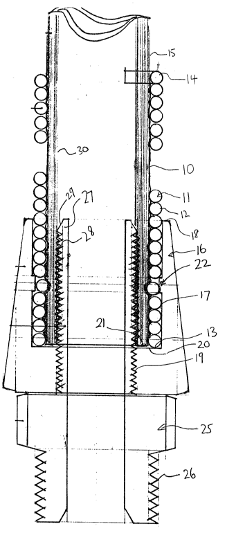
Figure 1 is a cross-sectional view of a hose connection according
to the present invention.
Figure 2 is a similar cross-sectional view showing a modified male
insert portion with a swivel couplin~.
In ~he drawin~s like characters of reference indicate correspunding
parts in the different fisures.
DETAILED DESCRIPTION
The hose connection comprises a flexible hose 10 of the type
formed from vinyl or similar soft material which is sometimes reinforced with a
fabric. The hose is however relatively collapsible and flexible and tends to
collapse or kink when pinched or bent at an angle to its normal direction. This
type of hose is however relatively inexpensive and is entirely suitable for low
pressure ~ype situations. For example in supplying liquid or foam in a car
wash.
The connection further includes a helical spring 11 of a constant
diameter and formed from a helically wrapped wire 12 extendin~ from a first
end coil 13 to a second end coil 14. The helical wire is wrapped so that the
turns are closely adjacent or substantially touching so as to form a subst~ntially
wholly closed cylinder. However the connection will also operate effectively
when using a spring which is slightly more open. The diameter of the sprin~ is

~0592~

selected so that it is a fric~ion fit with the outside surface 15 of the hose 10.
Thus it is necessary for the spring to be rotated relative to tha hose in a
direction to open the sprin~ to allow the spring to slide over the outside surface
of the hose. Ths sprin~ is relatively short so that it extends only over the
coupling s~ction with the hose of course extendin~ outwardly from the end 14
of the spring to supply fluid or liquid throu~h the hose to a remote location asrequired.
The connection further includes a sleeve member 16 defining an
interior cylindrical bore 17 openin~ at one end 18 of the sleeve member 16.
The sleeve member further includes a female bore portion 19 which is of a
reduced diarneter relative to the cylindrical surface 17 so as to form a shoulder
20 between the female bore portion 19 and the cylindrical surface 17.
The end 13 of the spring is coincident with an end 21 of the hose
and these ends are both abutted against the shoulder 20. An annular rib 22 is
provided on the inside of the sleeve member at a position approximately mid-
way alon~ the len~th of the cyiindrical surface 17. A male insert member 25
includes a screw threaded coupling por~ion 26 at one end for attachment to a
couplin~ nipple of a liquid supply duct. At ~he opposed end of the rnale insert
member 25 is provided an insert portion 27 which is cylindrical in shape and
has a male screw thread on the outside surface thereof for engagement into
the female screw thread 19 of the sleeve member. The outside diameter of the
insert portion 27 is equal to the diameter of the female bore 19 and also
therefore equal to ~he inside diameter of the hose so as to engaae against the
inside surface 30 of the hose. The thread 28 on the outside surface of the

-5- ~10~927

insert rnernber extends substantially along the full len~th so as to bite into the
inside surface 30 of the hose. A short inclined lead in section 29 is provided at
the end of the insert portion which reduces in diarneter from the outside
diameter of the thread sli0htly inwardly so as to assist in en~aging the end of
the insert member into the hose without pushing the hose lon~itudinally the
sleeve member.
The insertion of the insert member into the sleeve member
therefore acts to compress the hose between the threaded section 28 and the
inside surface of the sprin~ thus clampin~ or squeezin~ the hose section and
forcina the hose surface 15 into en~a~ement with the sprin~ so as to cause
some convolution of the outside surface to frictionally en~a~e with the sprin~.
The couplin~ system therefore provides a simple coupling of four
pieoes without any abutments on the outside surface which could be contacted
by a user. The spring protects the end of the hose against mechanical collapse
when pulled sideways. The sprin~ is automatically held in place by its
cooperation in the couplin~ system.
Turnin~ now to Fi0ure 2, the arran~ement shown and modified
only in relation to the male insert member 30 which in this case is provided as
a swivel connec~ion including a swivel member 31 and a fixed portion 32 which
en~a~es into the sleeve member 16 as previously described. The fixed portion
32 includes a cylindrical projecting portion 33 which receives the swivel
member 31 on the outside surface thereof. A recess 34 is defined between the
swivel portion and the cylindrical member 33 which receives an O-ring seal 35
within the recess 34. The swivel member is held in place on the cylindrical

-6- 2~0~927

portion 33 by a ri~id clip rin~ 36 which includes broken ends 37 allowing it to
be clipped in place within an annular recess within the outside surface of the
cylindrical portion 33. The swivel member 31 includes a screw thread section
38 for enga~in~ into a suppl~/ nipple. An end surface 39 of the swivel portion
31 is inclined to a radial plane so that sli~htly recessed back toward to the 0-rin3 35. This an~le of the outer surface 39 assists in retainin~ the clip ring 36
in place.
The swivel couplin~ is thus repairable to replace the O-ring seal.
In particular the clip ring is removable and is accessible in view of the
positioning at the end of the cylindrical portion 33. The clip rin~ can therefore
be accessed and removed using suitable players. When removed the male
cylindrical portion 33 can be removed from the inside of the swivel portion and
the O-ring removed unreplaced.
The simple swivel connection to the end of the hose allows the
hose end to be properly protected to prevent collapse when pulled to one side
and to preven~ twisting and collapse when rotated at the outer end relative to
the fixed supply nipple.
Since various modifications can be made in rny invention as
hereinabove described, and many apparently widely different embodiments of
same made within the spirit and scope of the elaims withou~ departin~ from
such spirit and scope, it is intended that all matter contained in the
accompanyin~ specification shall be interpreted as illustrative only and not in a
limiting sense.

Representative Drawing
A single figure which represents the drawing illustrating the invention.
Administrative Status

For a clearer understanding of the status of the application/patent presented on this page, the site Disclaimer , as well as the definitions for Patent , Administrative Status , Maintenance Fee  and Payment History  should be consulted.

Administrative Status

Title Date
Forecasted Issue Date Unavailable
(22) Filed 1993-09-10
(41) Open to Public Inspection 1994-03-11
Dead Application 1999-09-10

Abandonment History

Abandonment Date Reason Reinstatement Date
1998-09-10 FAILURE TO PAY APPLICATION MAINTENANCE FEE

Payment History

Fee Type Anniversary Year Due Date Amount Paid Paid Date
Application Fee $0.00 1993-09-10
Reinstatement: Failure to Pay Application Maintenance Fees $200.00 1996-03-01
Maintenance Fee - Application - New Act 2 1995-09-11 $50.00 1996-03-01
Maintenance Fee - Application - New Act 3 1996-09-10 $50.00 1996-09-10
Maintenance Fee - Application - New Act 4 1997-09-10 $50.00 1997-09-03
Owners on Record

Note: Records showing the ownership history in alphabetical order.

Current Owners on Record
WIEBE, JACOB
Past Owners on Record
None
Past Owners that do not appear in the "Owners on Record" listing will appear in other documentation within the application.
Documents

To view selected files, please enter reCAPTCHA code :


To view images, click a link in the Document Description column. To download the documents, select one or more checkboxes in the first column and then click the "Download Selected in PDF format (Zip Archive)" or the "Download Selected as Single PDF" button.

List of published and non-published patent-specific documents on the CPD .

If you have any difficulty accessing content, you can call the Client Service Centre at 1-866-997-1936 or send them an e-mail at CIPO Client Service Centre.


Document
Description 
Date
(yyyy-mm-dd) 
Number of pages   Size of Image (KB) 
Cover Page 1994-03-11 1 19
Abstract 1994-03-11 1 14
Claims 1994-03-11 2 60
Drawings 1994-03-11 2 54
Representative Drawing 1999-07-12 1 38
Description 1994-03-11 6 227
Fees 1996-09-10 5 172
Fees 1996-03-01 2 62