Note: Descriptions are shown in the official language in which they were submitted.
a"'' 92/16177 ~ ~ ~ J ~ r( ~ fCT/AU92/00110
4dALKING AiD
THIS INVENTION relates to a walking aid
suitable for use with patients suffering from spinal
complaints such as paraplegics and quadriplegics to walk
or move.
Hitherta such walking aids have comprised a leg
support apparatus, back support and chest support which
were all interconnected by rigid straps usually formed
from metal such as aluminium. The leg support apparatus
as well as the back and chest' support was normally formed
from moulded plastics material. It was a characteristic
of such conventional walking aids that the waist and
chest support was pivotally attached to the leg support
apparatus by a pair of pivot joints located in the nip
region. By the provision of hip pivot. joints or hinges
it has now been ascertained that this planed considerable
stress on the hip pivot joint when the patient swayed
from side'to side which is an essential part of the
walking action. This means that a particular hip pivot
joint supported substantially the entire weight of one
leg which placed a severe bending movement on the hip
pivot joint and especially on the bearing housing
utilised in the pivot joint. This resulted in frequent
breakage of the bearing housing and thus conventional
walking aids as .described above were subject to frequent
maintenance, repair or replacement.
One conventional walking aid of the type
referred to above was known as the PARAWALKER from the
United Kingdom wherein the leg support apparatus included
a foot support, knee support, and thigh support. Another
conventional walking aid of the type described above cans
the LUISIANA from the United States wherein the leg
support apparatus. included a single foot and shin support
as w~11 as a thigh support.
. . . - - Another conventional walking aid emanated from
Germany andw included a-pair of leg members each having
knee and thigh supports formed from leather-straps
interconnected by vertical metal arms. There was also
W~ 92/161?7
~crm u92/ooa j o,~,-.-.
2
included a flexible waist harness connected to a pair of
upper thigh supports of,e,ach leg member. The upper thigh
supports were spaced from each other by a spacer plate.
There was also provided a pair of rods with each rod
being attached to an adjacent lower leg member. Each rod
was pivotally attached at an upper end thereof to the
spacer plate. Tn this arrangement each leg member was
therefore pivotally attached to the spacer plate far
reciprocatable movement thereto simulating a walking
action. However in this German walking aid there was no
provision for a bearing between the spacer plate and each
leg member which was necessary if the walking aid was
useful for paraplegics or quadriplegics. The main reason
fox provision of the spacer plate was to keep the legs
apart so_that they did came into contact.
Tt is therefore an object of the invention to
provide a walking aid which may alleviate the
disadvantages of the prior art discussed above.
The walking aid of the invention :includes a
body support member and a pair of leg support members
each of which are interconnected by a central or crutch
pivot means so as to be independently pivotally movable
with respect to each other.
The body support member may be of any suitable
type and thus be rigid or flexible. Preferably in one
embodiment the body support member includes a back
support member. Suitably the back support member
comprises a back frame having a plurality o~ frame
members. Tn one preferred form the back support member
30, may include a rear frame member extending away from the
central .pivot means. Suitably the rear frame, member
extends substantially horizontally or slightly upwardly
with respect, to the horizontal and then,. vertically
upwardly .so as, to correspond to . the contour of a
patients back. A chest bracket or frame member may be
attached to an upper end of the frame member which may be
curved or arcuate in, plan. The chest bracket may have
w0 92/d617~7 2 ~ U ;~ ;~ n~ ~ PCT/AU92/00110
3
opposed ends interconnected by a chest belt or flexible ,
strap. ,
However the above arrangement is not essential
i
and thus the rear frame member may have cross members
attached thereto for supporting the back of a patient at
any suitable location. Alternatively the rear frame
member may be bifurcated if desired.
The leg support members may be o~ any suitable
type and may include leg support frames or leg support
brackets which can support both the thigh and shin.
It is preferred however that the leg support
member may simply comprise an attachment member which may
be attached to an associated leg support such as a leg
calliper such as those utilised in the aforementioned
PARAWALRER or LUISIANA walking .aids. Alternatively the
attachment member may include a housing or casing being a
suitable socket member for retaining a mating plug member
or mounting projection of an associated leg support in
either push fit or interference fit relationship.
Alternatively clip means or other, appropriate .attachment
means may be utilised if required eg providing fasteners
(eg screws or rivets interconnecting mating parts of the
attachment member and the leg calliper.
The pivot means suitably comprises a bearing
housing and a pair of bearings. which are independent of
each other so as to enable an associated leg support
member to be independently movable. of the other. The
bearings may be of any suitable type and thus include
rolling element bearings. such as ball bearings or roller
bearings or plain, bearings inclusive of bushings.
Preferably ball bearings are utilised as they are a low
friction bearing which will also withstand a reasonable
amount of thrust.
The bearing. housing may: be tubular and suitably
--35 if. the bearing is a ball- bearing. there is included an
inner race or casing andwan outer:.race:.:or casing with
balls interposed therebetween. The outer casing is
wo ~aea~s~~7 ~~4 ,~~ ~ Pcrinu9zioono~...
suitably a very tight fit. or interference fit within the
tubular bearing housing.
The tubular bearing housing may be of any
suitable shape but may have an arcuate or circular
internal surface. An outer surface of the tubular
bearing housing may have extending outwardly therefrom at
least one stop and more preferably a plurality of stops
to prey~nt the leg support members from contacting each
other .and thus facilitate unimpeded movement by the
patient.
There also may be provided means fox
restricting rearward movement of each of the leg support
members so as to enable a patient using the walking aid
of, the invention to achieve proper balance when in a
standing position. Without such restricting means it may
be necessary for the patient to use a walking stick. or
other support placed well to the rear to obtain a proper
balance position or balance point. A suitable form of
restricting means includes each leg support member also
including ons or more stops which engage with a
rearwardly oriented stop of the tubular housing. however
in another alternative such restricting means may.
comprise. each leg support member having appropriately
located abutment projections or stops contacting mating
projections of the rear, frame member at the balance
point. In another possible arrangement the tubular
bearing housing may have suitably located abutment
members or stops which engage with respective edges of
the leg support members at the balance point.
There also may be provided attachment means for
attachment of each leg support member to the tubular
bearing housing. This may include the use of fasteners
such as nuts .and bolts or clip means of - a suitable type .
. __: ; ,;: Freferably._.~the attachment m~ans ~.s al.so utilised to
35_; attach. each : .bearing associated with '- an - adjacent leg
support member in.the bearing housing. '
In. another embodiment of the invention the body
v'~D 92/d6d77 ~ ~ ~ J ~ ~~ ~ PCf/AU92/UOd d0
support moans may be modified to comprise a harness or
more suitably a belt worn by the patient around his waist
,. and thus the back frame having a plurality of frame
members may be dispensed with. In this regard it has
5 been established that in some cases it may not be
desirable to have any back support member in contact with
the spine or coccyx and thus avoid any contact with
relevant pressure points in these areas. With these
points in mind the walking aid of the invention may
include the central or crutch pivot means referred to
above, a waist belt which is attached to the pivot means
and a pair of leg support members as discussed above.
In this embodiment of the invention the body
support member may be used to support the pivot means in
the desired position adjacent the crutch. The pair of
leg members may each comprise a pair of attachment
members which may each be attached to an associated leg
support such as a calliper or specialised leg supports
such as the K.A.F'.O.S. referred to previously (ie. knee
ankle foot orthoses).
Suitably in this embodiment the crutch pivot
means may include an axle which is attached to each of
the lag attachment members. In this arrangement each leg
attachment member may include a head part or upper part
which may be hollow so that the axle may extend through
aligned bores or internal passages located in each head
part or upper part, Preferably in each bore or internal
passage there is provided a plain bearing or bush
suitably made of plastics material or ceramic material or~
even metal which may be moulded to the adjacent byre or
internal passage or otherwise attached thereto. If
necessary the bush or plain bearing may be dispensed with
and replaced by a bearing surface. of the internal passage
or. bore -which may. be suitably prepared or modified to
. 35, allow rotatable movement by an associated leg~,attachment
member. ~ ' , .
The body support means may also include one or
~'v'092/16177 ~~~ j~~ ~ YCT/AU92/0011;L~~--.
1 6
more connection members between the crutch pivot means
and the belt. In one suitable arrangement the connection
members may include connection straps which may be
attached to the belt in any suitable manner such as by a
fixed attachment which includes welding or stitching or
being looped through a suitable attachment aperture or
slot provided in the belt. This latter form of
attachment may also be adjustable. Each connection strap
may also be attached to the crutch pivot means.
In this embodiment the crutch pivot means may
include a bearing support member to which each of the
connection straps may be attached thereto in any suitable
manner such as by stitching or welding for example.
However it is preferred that the attachment between the
bearing support member and each connection strap is
adjustable and this .may be achieved by each connection
strap being looped. through an associated aperture or slot
in the bearing support member and with a free end of the
connection strap being attached to the remainder of the
strap by a velcro interconnection or buckle or other
attachment of an adjustable nature.
If desired the adjustable attachment between
each connection strap and the bearing support member may
be replaced by a fixed attachment and instead there may
be utilised an adjustable attachment between each
connection strap arid the support belt as described above.
However the former arrangement is preferred.
w,The bearing support member may comprise a
member leaving the shape of a substantially inverted U
with the connection straps being attached to the base. of
the U and the axle being supported by internal bores or
apertures in the arms of the U.
In another embodiment .the inguinal straps may
be~modified so that-they intersect or are crossed over so
-.that.one..inguinal:stra~ attached to a right side of the'r
waist belt in use. is attached to a right leg support '
member and an,inguinal. strap attached to a left side of
~"~J 92/16177
PCf/A U92/U0110
7
the waist belt is attached to a right leg support' member.
In regard to the above embodiment both of the
leg support members rnay be provided with a support loop.
There also may be provided a releasable locking
means whereby the wearer or user of the walking aid of
the invention may attach both of the leg support members
to the KAFO~s. The locking means may be of any suitable
type and preferably is a snap-on locking system which is
readily releasable by actuation of a movable release
member which may be moved linearly but is more preferably
pivoted from a locked position to an unlocked position.
Reference may now be made to a preferred
embodiment of the invention as shown in the attached
drawings wherein:
FTGS 1 and 2 illustrate the abovementioned
prior art walking aids comprising the PARAWALIZEFt and
hUISIANA devices respectively;
FIG 3 refexs to a perspective view of a first
type of walking aid constructed in accordance with the
invention;
FIG 4 refers to an exploded perspective view of
the walking aid shown in FIG 3;
FIG ,5 refers to a second type of walking aid
constructed in accordance with the invention wherein the
back support member is omitted.
FIG 6 refers to a third type of walking aid
constructed in accordance with the invention similar to
that shown in FIG 5;
FIG 7 refers to an exploded perspective view of
the walking aid shown in FIG 6;
FIG 8 is a sectional view of an assembled
walking aid shown in FTG 6;
FIG 9 is an enlarged va..ew of the track. fox
engagement with the cam trigger.shown.in FIGS 7 and 9;
-- FIG 10 is a sectional view of the cam trigger;
and . .
FIG 11 is a perspective view of the cam
'~'f3 92/16177 PCd'/AU92/U0110,,..,,
~~ l.~r~t~r~ ~ 8
trigger.
In the PARAWALRi;R device 10 shown in FIG 1
there is included leg callipers 11 including foot
supports 12, knee supports 13 and rear leg supports 14.
There is also shown back support 15 and chest support. i6.
Straps 17 interconnect foot supports 12 and knee supports
13. Straps 18 interconnect chest support 16 and back
support 1S. Chest support 16 also has chest pad 19.
There is also shown hip joints 20.
In the LUISIANA device shown~in FIG 2 there is
included leg callipers 21 comprising foot supports 22 and
upper leg supports 23 interconnected by straps 24
attached to foot supports 22 by attachment 25 and
attached to upper leg supports 23 by attachments 26.
There is also shown knee joints 27 comprising washer 28
and pivot joint 29 separate from each ather and in the
unlocked position. In the locked position washers 28
engage with pivot joints 29. Also shown are hip joints
30, bank support 31, chest support 32 and straps 33A
interconnecting chest support 32 and bank support 31.
Also shown are actuating cables 33 and 34 which Work in
conjunction with hip joints 30.
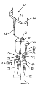
In .FIG 3 the walking aid 40 of the invention
includes bearing housing 41, lag attachment members 42,
back support member 43 in the form of a rear frame member
and chest bracket 44 having associated therewith
attachment members 46 for a chest belt (not shown). The
leg attachment members are shov.-n attached to leg
callipers 21 already described in FIG 2 above. However
it will be appreciated that leg callipers 11 shown in FIG
.1 could also be attached to leg attachment members 42 if
considered apprt,priate. Alternatively the leg callipers
could be integral with the leg attachment members 42 so
that the leg support members of the walking sid.of the
invention ' include Grithin their ~.seope ' Lithe ~ attachment
members with the leg callipers~omittedlor the assembly of ,
attachment members and leg callipers.
WO 92/16177 ~ ~ ~ j ~ ~~ ~ PCT/AU92/00110
9
In FIG 4 there is shown the walking aid 40 of
the invention in greater detail. The tubular housing 41
has rear stop 45 and a front stop 47 which each extend
the full width of housing 41 although it will be
appreciated that this is not essential. Accommodated
within the bore 48 of bearing housing 41 are bolts 49,
bearings 50 having inner race 51 and outer race 52 and
spacers 53. Bolts 49 are spaced from each other within
bore 48 so as to provide a pair of bearings 50 which
function independently of. each other. There is also
shown nuts 54 engageable with threaded ends 55 of bolts
49. The outer race 52 of each bearing 50 is a tight fit
or interference f~,t within bore 48. Bolts 49 extend
through aligned apertures 56 of attachment members 42 as
shown.
Each attachment member 42 is provided with
adjustable stops 57 which may engage with rear stop 45 of
tubular housing 41 to achieve the balance.~point described
previously. The leg calliper may be attached to a
selected one of apertures 58 or 59. The back support
member 43 may be formed from separate components if
desired and jointed at locations 60 and 61 if
appropriate. The position of the chest bracket 44
relative to bank support member 43 may also be adjustable
by the provision of fasteners 62 engageable in attachment
slot 63.
In FIG 5 there is illustrated a body strap 70
adapted to be worn around the waist having a buckle 71
and velcro attachment parts 72 and 73 for adjustment.
This may be replaced by a conventional buckle assembly if.
desired which includes a buckle tongue which engages with
a selected hole in the belt. There is also shown
connection or inguinal straps 74 attached to belt 70 at
75. ~:.;. Each connection- belt' 74 includes. :av,loop 76 having a
., ..free . end 77 attached to. the remainder. of : strap 74.;via av°.
_,
velcro attachment at 78. This provides an adjustable
attachment as described above. This enables the straps
~'0 92n 6177 ~ ~ ~ t~ ~ '~ PCT/AU'92/00110,.-...,
74 to be tensioned arid thus stabilise the patient wearing
the walking aid of the invention in a standing position.
There is also shown crutch pivot means 79 which
includes bearing support member 80 which has downwardly
5 depending projections 82, 83 and 84 which have aligned
apertures 85, 86 and 87 for retention of axle 88. In one
projection 82 there may be provided a blind hole which
constitutes aperture 85 which retains an associated end
89 of axle 88. The axle 88 may be retained in desired
10 position in projection 82, 83 and 84 by a grub screw (not
shown) which extends through projection 83 or be provided
with a threaded end (not shown) which engages with an
internal thread located in projection 84 (not shown).
Alternatively axle 88 may comprise two shafts each
threaded in central projection 83.
Each leg member 90 is connected to the leg
brackets (not shown) by bolts or snap fit or interference
fit or alternative form of connection. Each leg member
90 also has an extended upper part 91 having an internal
bore 92 which may be lined by a plain bearing or bush 93
which may be moulded in each bare 92 or attached thereto
by an interference fit or other suitable connection.
In FIG 6 there' is shown a modified walking aid
of the invention when compaxed to the embodiment of FIG
2S 5. The waist belt 100 has a buckle 101 and velcro
attachment parts 102 and 103 for adjustment. The
inguinal straps 104 and 105 are attached to waist belt
100 at 106 and 107 respectively by stitching or other
form of attachment. The inguinal straps 104 and 105 are
crossed or intersect at 108 so as to abut each other so
that the right hand strap is looped through loop I09
attached to left leg support member 110 and the left hand
strap- 105 is looped through loop lli attached- to the
..:-.right :leg 'support=member 112. -- The f,~ree end ~ of each strap
104 and 105 may--be attached to the-strap by velcro or~-
Bother suitable form of attachment at'108A and 1088."
. The reason for the crossover is that b'y
~vr~ 9maba7~ ~ 1 ~~'~ ~ ~~.~ PC?/AtJ92/001a0
11
twisting the body cg to the right this puts tension on
strap 104 which assists the left leg to be moved forward.
In similar manner when the body is twisted to the left
the right leg is assisted to move forward. The crossover
is preferred because the natural swing of the body causes
a twisting movement and this is utilised to assist in the
rhythmic walking action.
It should be noted that the walking aid of the
invention_ is based on a hip guidance orthosis or a.
. pendulum effect and in some cases of lower level injuries
the crossover may not be of assistance except possibly
fox walking up an incline or steps where a twist of the
trunk would thrust the leg forward when the pendulum
inertia is not present. However in the case of high
level spinal injuries and part~.cularly with a wide waist
belt swinging the upper body even as high as the
shoulders particularly in the case of a quadriplegic the
energy transmitted from the upper body in the wide belt
through straps 104 and 105 to bearing 113 .definitely
assists in walking. The belt 100 also gives the user
excellent body support as in most cases people suffering
from spinal injuries have lost muscle control in the
stomach region.
FIGS 7-8 show a detailed view of a modified
bearing means 113 for use in the invention through which
leg support members 110. and 112 are pivotably attached
thereto. The bearing means 113 includes axle bolt 114,
spacer 115, bush 116, bearing..117, washer 118 and locknut
119 which is screw threadedly engaged to bolt 114 at 120.
The bush 116 may take the role of a thrust bearing. Each
leg support member 110 and 112 includes bores 121 and 122
for retention of bearing 113 and axle bolt 114. It will
be. appreciated. that a number of different spacers 115
could be used so as to .. adjust:.. the ..:. distance between
support ~ members-=. 1.10 and.- 112. This : will : enable various
users .to be fitted with..the walking aid of ahe invention
as some paraplegics have varying levels of thigh muscle
WO 92/1b177 PCT/AU92/OU110~
12 ,
wasting.
There also may be provided releasable locking
means 123 between each support member 110 and 112 and the
KAFO's. The locking means may include a cam trigger or
release member 124, a cover member 125 having apertures
126 and 127, as well as central aperture 128 and upper
shallow projection 129. Aperture 128 accomodates
trigger 124 and projection 129 abuts trigger 124 as shown
in FIG 8. There is also provided a slide member 130
having upper and lower apertures 131 and 132, a slot 133,
a cam track 134, and a shaft 135 having a retaining
passage 136 for retention of cam spring 137 and cam
retaining screw 138 which also extends through aperture
139 of oam trigger 124. There is also provided a slide
spring 140 for biassing slide member 130.
The lag support member 112 includes an elongate
recess 141 for retention of cam trigger 124, cover member
125 and slide 130 and associated components described
above. There is also shown apertures 142: and 143,
aperture 144 for retention of cam retaining screw 138 as
well as apertures 145 and 146 for retention of retaining
screws 147 which attach arm 112 to cover member 125.
Recess 141 also includes surround flange 148.
The KAFO's attachment member 149 includes two
studs 150 and 151 each having slots 152 and 153. Each
stud fits through aligned apertures 142 , 131 and 126 and
143, 132 and 127 respectively. There are also included
RAFO~s attachment apertures 154 and 155. It will be
appreciated that the location of the attachment apertures
154 .and 155 may be variable not only widthwise having
regard to enlarged parts 155A but also lengthwise in
relation to attaohment member 149 as may be required.
This.~enables the bearing 113 to be moved in accordance
with the posture of:the.:user: ~ .. ... .
... ,._, : In - operation of:. the releasable locking ~ means
,123 cam trigger 124 .may: be piiYoted from a locked' position
shown in FIGS 8 in full outline to an unlocked position
~N~ 92/1C>177 ~ ~ o ~ f~ '~ ~ PCf/AU92/OU110
13
shown in phantom. The cam trigger 124 has a curved
projection 156 which may engage track 134 in the locked
position and be held in this position by the bias of
spring 137. There is also provided locating rib 156A and
the track 134 may also include trigger stops 156B as well
as mounting plate 156C as best shown in FIGS 9-11. Upon
rotation to an unlocked position the projection may ride
aver bearing rib 157 and be retained on plateau 158 also
the bias of the spring 137, When the cam trigger 124
moved from the locked to the unlocked position the spring
140 causes movement of slide member 130 so that the slide
plate may disengage with slots 152 and 153 and thus
release member 149. When the cam trigger 124 is moved to
the locked position the spring 140 pushes the slide
member 130 upwardly to that the slide member engages
slots 152 and 15~ and thus lock member 149 to leg support
member 112.
It would be appreciated from the foregoing that
the walking aid of the invention provides substantial
advantages over the prior art as discussed previously.
These advantages are as follows:
1. The bearing housing may be located in the
crutch area of the user which therefore is of great
comfort to the user and not visually obvious especially
when wearing clothes. Thus the walking aid of the
invention is not obvious to an observer as it can be worn
under the clothing.
2. The walking aid of the invention if formed from
light weight plastics material would be extremely light
in practice and would weigh a lot less than the prior art
devices previously described. For example the walking
aid of the invention would weigh approximately 4kg when
compared to a PARAWALKER device which would weigh
approximately lOkg.
3. The walking aid of the invention is extremely
simple and efficient in use and doss not have the
complexity of the prior art devices. This makes it
WO 92!16177 ~ ~ ~ j ~ ~ '~ PCf/AU92/00110~-.,,
14
cheaper to manufacture. ,
4~ It is possible for the walking aid of the
invention to be manufactured using a series of
interfitting modules or standaxd components. In this
regard the user, while in a sitting ~ position, may simply
attach each of the leg callipers to the leg support
members or leg attachment members.
5~ The provision of a central pivot joint in the
crutch area results not only in concealing of the
bearings but also reduces the stresses which axe present
in the prior art devices. This reduces costs insofar as
maintenance, repair or replacement is concerned. As
mentioned above the prior art devices were subject to
damage if the whole weight of one leg was concentrated on
one hip joint.
~ The walking aid of the invention may be made
entirely from plastics material which makes it suitable
for production by injection moulding, compression
moulding or other form of plastics moulding process.
This is not the case with the prior art..
The combination of the waist belt, inguinal or
connection straps, crutch pivot or bearing and leg
support members provides a cohesive walking aid for
patients suffering fxom spinal injury and has the
advantages described above.