Note: Descriptions are shown in the official language in which they were submitted.
2 2 9
2217-21-00
PAT~NT
AUTOMATED DIAMETER GAUGING SYSTEM
BACKGROUND OF THE INVENTION
Field of the Invention
This invention relates to measurin~ systems for three-
dimensional objects. In particular, this invention relates to an
improved method of and apparatus for making the measurement of the
diameter and circumference of three-dimensional objects which are
easily deformable, wherein normal dimensions are difficult to
maintain during measurement.
Description of Related Art
An air bag inflator for use in a driver side air bag module or
a passenger side air bag module comprises an outer rigid housing,
a filter unit containing filter screens and filter material, gas
generating material, an inner housing, and igniter material.
Screen elements, which are flexible units having a circular cross
section, are normally manufactured by rolling individual units of
screen cloth around a mandrel and spot welding the screen at a
number of locations in order that the screen unit retains its
circular cross section. Herein, flexible is defined as a semirigid
object which is readily deformed from its normal shape by the
application of light compressive force. These screen elements must
be manufactured to within close tolerances to provide for proper
assembly of the air bag inflator unit. Sample screen elements are
tested periodically to verify conformance of the diameter and
circumference of the screen elements to within specified
tolerances.
Diameter and circumference measurements of the screen units
must be done by means which do not distort the flexible screen
elements in order to obtain the correct measurements. Also, the
2 2 ~
2217-21-00
PATENT
measuring device should be capable of correcting for screen
elements which have been distorted from their normal shape due to
handling. Therefore, conventional measuring devices such as
calipers or the like cannot be used due to possible deformation of
the screen element resulting in incorrect measurements.
Solutions have been suggested for the measurement of rigid
cylindrical objects. Golinelli et alO, U.S. Patent No. 4,543,725;
Vreeland, U.S. Patent No. 3,303,572; and Geiler et al., U.S.S.R
Inventor's Certificate (11) 521~51, disclose devices for checking
the external diametrical dimensions of rigid circular parts.
Golinelli utilizes a support means and two feelers which move with
respect to the support. A transducer provides an electrical signal
proportional to the position of the feelers. Vreeland utilizes two
probes mounted 90 from one another and connected by a spring
member. As the diameter is measured, the spring member expands or
contracts and the strain is measured and converted into diametrical
measurements. Geiler discloses a gauge with three probes attached
to two cylindrical half-rings compressed onto the object by twin
springs. The gauge is held to the object to be measured by three
axial stops. Measurement is taken by two fixed measuring probes
and one sensitive measuring probe. These apparatus rely on
measurement of cylindrical objects by probes contacting the object
at a fixed number of points. Further, these apparatus do not
readily compensate for objects which have an elliptical cross
section~
Ano~her measuring device known as a pi tape can be used to
measure circumference. This apparatus has the advantage of
accommodating the deformation of the object to be measured, but
2 '~ ~
2217~ 00
PATEN~
does not compensate for elliptical error. Further, this device is
difficult to use and is prone to operator error due to variability
in interpolation of the reading required of the operator to
determine the final measurement. Alternative measurement systems
include visual identification systems and laser gauging systems.
These systems are accurate and highly reproducible. They are
costly, however, and sometimes slow in operation.
SUMMARY OF THE INVENTION
An object of this invention is to provide a method of and
apparatus for the accurate measurement of the cross section of
flexible three-dimensional objects.
Another object of this invention is to provide an improved
method of and apparatus for the rapid and accurate measurement of
the diameter and circumference of readily deformable three-
dimensional objects having a circular cross section.
Another object of this invention is to provide an improved
method for making the measurement of a deformable three-dimensional
object which when not deformed has a circular cross section.
Another object of this invention is to provide an improved
method for making the measurement of a deformable three-dimensional
object which has been deformed from a circular cross section by
reshaping the cross section of the object to form a circular cross
section and then measuring the object.
Another object of this invention is to provide a means for
2 ~ ~
2217-21-00
PATENT
forming a flexible elliptical object into a circular shape and then
determining the diameter and circumference of the object.
Another object of this invention is to provide an impxoved
means for determining the diameter and circumference of a flexible
circular tubular object, a means which is not substantially
susceptible to operator error.
These and other objectives of the invention, which will become
apparent from the following description, have been achieved by a
novel device for measuring flexible objects having a circular cross
section comprising a circle or sphere machined into a solid plate.
The plate is then split along the axis thus forming a first caliper
and a second caliper. The first caliper has a first surface and a
second surface and the second caliper has a first surface and a
second surface. One caliper piece is fixed to a base. A
cylindrical or spherical pocket of particular size and shape
conforming to the part to be measured is located symmetrical to the
center axis of the two halves. The free caliper is attached in
such a manner as to slide toward and away from the fixed caliper,
capturing the part to be measured in the circle. The part being
measured holds the two calipers apart by conforming to the inner
shape of the gauge and opposing the ~orces moving the two calipers
together. A gap is formed separating the two calipers. The length
of the gap can be mathematically related to either the
circumference or diameter of the part being measured.
Closing th~ calipers on the part places the part in
compression. This forces the part to be symmetric and eliminates
most of the irregular or elliptical shapes which may occur.
2 ~?~ ~
2217-21-00
PATENT
Placing the part in compression also reduces the flexibility of the
part and allows consistent and repeatable readings. Sensor
readings are processed by a device capable of refinin~ the data and
providing it in a usable manner.
The first surfaces of the two calipers or gauge pieces may be
connected by a flexural means such that a single gauge piece is
formed. The gauge is then compressed around the flexible circular
object to be measured and the distance of separation is determined.
The separation is compared to that caused by a reference object and
the result is converted to diameter and circumference measurements
by appropriate means.
Further, this invention includes a method for measuring
deformable three-dimensional objects comprising the steps of moving
a first caliper relative and in linear relation relative to a
second caliper, with a flexible object to be measured therebetween,
thereby placing the flexible three-dimensional object under
compression. The method of this invention also includes the step
of determining the length of a gap separating the first caliper
from the second caliper. This method of this invention also
includes the step of comparing the length of the gap separating the
first caliper from the second caliper when the flexible object to
be measured is placed between the first caliper and the ~econd
caliper with the length of the gap separating the first caliper
from the second caliper when a rigid reference object is between
the first caliper and the second caliper. The method of this
invention also includes the step of calculating the diameter of the
three-dimensional object having a circular cross section by
multiplying the difference in the length of the gap obtained from
2 i~. ~
2217-21-00
PATENT
the previous step by 2, diving by ~, and adding the diameter of
the reference. The method of this invention also includes the step
of providing an output.
BRIEF DESCRIPTION OF THE DRAWINGS
With this description of the invention, a detailed description
follows with reference being made to the accompanying figures of
drawing which form part of the specification, in which like parts
are designated by the same reference numbers, and of which:
Fig. l is a top plan view of the measuring device illustrating
the measuring device of this invention;
Fig. 2 is a side plan view o~ the measuring device
illustrating the position of the first caliper, the second caliper,
and the compression means;
20Fig. 3 is a fragmented side plan view of the measuring device
illustrating the compression means and the release mechanism;
Fig. 4 is a top plan view of the measuring device illustrating
the measuring device of this invention with a single piece gauge;
Fig. 5 is a top plan view of the measuring device illustrating
an alternate configuration of the device;
Fig. 5a is a close-up of a back plan view the device of Fig.
305 illustrating a computer compatible connector; and
~Z ~ 2 9
-
2217-21-00
PATENT
Fig. 6 is a front plan view of the measuring device further
illustrating an alternate configuration of the device.
DETAILED DESCRIPTION OF THE INVENTION
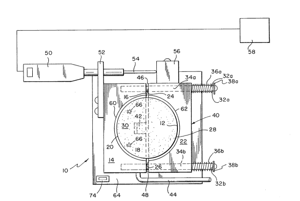
As bsst seen in Fig. 1, a measuring device shown generally at
10 is provided for measuring the diameter and circumference of a
10flexible object 12 (as shown in Fig. 3), having a circular cross
section. The measuring device 10 includes a first caliper 14
having a first surface 16, a second surface 18, and an inner
circular edge 20 and a second caliper 22 having a first surface 24,
a second surface 26, and an inner circular edge 28. When the first
15caliper 14 is placed in side by side relationship to the second
caliper 22, with the respective first surfaces 16 and 24 and second
surfaces 18 and 26 opposite one another, a substantially circular
opening 30 is defined. The first caliper 14 and the second caliper
22 are connected by linear tracks ~2a and 32b. The linear tracks
2032a and 32b are attached to the first caliper 14 and pass through
channels 34a and 34b in the second caliper 22. Springs 36a and 36b
on linear tracks 32a and 32b between end caps 38a and 38b and the
second caliper side edge 40 exerts force on the second caliper 22
moving it toward the first caliper 14. The movement of the second
25caliper 22 is opposed by a cam 42 attached to a lever 44O
When lever 44 is moved cam 42 permits the second caliper 2~ to
move in a linear relation relative to the first caliper 14 placing
the object 12 to be measured under compression. The gaps 46 and 48
formed between the first surfaces and the second surfaces
- 7 -
- æ~229
2217-21-00
PATENT
respectively are measured by a distance measuring device 50
attached to the first caliper 14 by mounting fixture 52 with the
measuring device probe 54 contacting stop 56 attached to the second
caliper. This gap separating the first caliper 14 from the second
caliper 22 is compared to the gap formed by a re~erence cylinder
(not shown). The comparison is converted into appropriate units by
a calculating means 58 attached to distance measuring device 50.
The first caliper 14 and second caliper 22 together form a
circular gauge for measuring the diameter and circumference of
flexible circular objects. The two calipers can be manufactured
from a solid block of rigid material. A circular hole with a
diameter equal to the nominal diameter of the calibration object is
cut through the block. The top edges 60 and 62 (as shown in Fig.
2) of the first and second calipers respectively, may be beveled to
aid in guiding the placement of the object 12 to be measured.
Channels are drilled into the block on either side of the central
circular opening. The block is then cut in half perpendicular to
the channels by removal of about 0.1 inch of material. Straight
tracks or rods are inserted into the channels to permit the two
gauge sections to travel in a side-by-side substantially linear
relationship to one another. The straight tracks or rods may be
secured in one of the guide pieces thus permitting the second guide
piece to move in a side-by-side substantially linear relation to
the first guide piece. The first caliper can then be secured to a
base 64 by fasteners 66 or the like to provide a mounting surface
for other components. The straight tracks extend beyond the edge
of the second guide piece to accommodate compression means.
Inserts tnot shown) can be added to reduce the diameter of the
gauge thus providing for the measurement of flexible circular
% ~ J 9
2217-21-00
PATENT
objects of varying diameter. The inner edges 20 and 2~, although
shown herein as circular can be of any shape required to conform to
the cross section of the object to be measured.
The two calipers or gauge piece may also be partially severed
so as to leave a section connecting the first caliper 14 and the
second caliper 22 effectively forming a single gauge piece 68, as
shown in Fig. 4. The flexural section 70 thus formed can function
as a compression means or a separate compression means may be
provided.
The compression means forces the gauge sections together. The
force provided by the compression means must be such that when
conducted through the gauge sections the flexible object is
compressed to conform to the circular opening formed by the two
gauge pieces. The force provided by the compression means must be
sufficient to force the flexible object to conform to the shape of
the two gauge pieces; however, the compression means must not be
such as to cause the flexible object to collapse or deform other
than to conform to the shape of the gauge. The compression means
can be any suitable means to meet the requirements stated
hereinabove. A spring, pneumatic compression de~ice, or a
hydraulic compression device may be used. A spring is preferred
due to low cost and low maintenance which results from its use.
Once the flexible object to be measured has been compressed,
the gauge pieces must still be separated by a slight gap. ~his gap
is measured by any appropriate means such as a measuring tape,
calipers, electronic measuring gauge digital measuring gauge or the
like. A digital measuring gauge with a computer compatible output
2 L~6229
2217-21-00
PATENT
is preferred since the data can be outputted to a computational
device for mathematical and statistical analysis. A device of this
type, such as a DIG~MATIC INDICATOR~, having a one-inch stroke and
a standard BCD output, is manufactured by Mitatoyo Corporation, of
Tokyo, Japan. A converter 72 for the conversion from BCD to RS-232
or from BCD to IEEE can be used to provide a computer compatible
output for the calculating device 58. Any suitable personal
computer or hand held computational device can be used as the
calculating device 58. An HP-4~3SX was used due to the ease of
operation, size, and the presence of a built-in RS-232 interface.
A program for the HP-48SX to take 5 readings, to convert the output
of the Mitatoyo DIGAMATIC INDICATOR~ to a dimensional number, and
to calculate the means and standard deviation appears at the end of
the specification.
To measure a flexible object, an object is inserted into the
measuring device between the first movable measuring device and
second movable measuring device as shown in Fig. 3. Lever 44 is
rotated so that the cam 42 separating the two gauge pieces is
rotated down thus permitting the compression means to force the two
gauge pieces together and compressing the flexible object to be
measured and forming it into a circular shape. As the lever ~4
completes its rotation it closes a microswitch 74 (as shown in Fig.
2) indicating a measurement is to be taken by the computer. The
distance measuring device 59, which is mounted to the first caliper
14 by mounting fixture 52 contacts a stop 56 on the second caliper
22. The distance between the two gauge pieces is transmitted to
the conversion device means 58 when the microswitch 74 is closed.
The gauge is zeroed periodically prior to thP taking of
measurements with the aid of a reference cylinder having a
-- 10 --
2 2 ~
2217-21-00
PATENT
specified diameter. The computer then calculates the difference in
diameter between the reference and the flexible object measured
using the equation:
tGauqe output) * 2 + Diameter of Reference
7r
Several samples are measured and the average and standard deviation
of the samples is calculated by mathematical routines available for
the computer.
The components of this invention although illustrated in Figs.
1-3 in one pos~ible arrangement can be arranged differently for
convenience and ease of operation without deviating from the intent
of the invention. As shown in Figs. 5, 5a and 6, for example, the
measuring device 5U may be placed beneath the calipers to reduce
the total area or "footprint" of the invention. The calculating
means 58 may be located adjacent to the calipers or located some
distance away. Converter 72 can placed below the calculating means
58 for convenience. An adapter 76, as shown in Fig. 5a, is
provided to attach the device of this invention to a computer or
the like is provided. Pneumatic pistons 78a and 7~b may be used in
place of lever 44 and cam 42 to separate the calipers. The linear
tracks 34a and 34b are secured by track supports 80a and 80b. A
sensor 82 detects the presence of the object 12 to be measured.
The pneumatic pistons ~8a and 78b are then deactivated thus
allowing springs 36a and 36b to compress object 12 and a
measurement is taken. A cover 84 is provided to protect the
device.
Thus, in accordance with the invention, there has been
-- 11
2 2 ~
2217-21-00
PATENT
provided a method of and apparatus for the rapid and accurate
measurement of the diameter and circumference of readily deformable
three-dimensional objects having circular cross section. There has
also been provided an improved method for making the measurement of
a deformable three-dimensional object which when not deformed has
a circular cross section. There has also been provided an
improved method for making the measurement of a deformable three-
dimensional object which has be~n deformed from a circular cross
section by reshaping the cross section of the object to form a
circular cross section and then measuring the object. There has
also been provided an improved method of and apparatus for forming
a flexible elliptical object into a circular shape and then
determining the diameter and circumference of the object.
Additionally, there has been provided an improved method and
apparatus for determining the diameter and circumference of a
flexible circular tubular object, the means which is not
substantially susceptible to operator error.
With this description of the invention in detail, those
skilled in the art will appreciate that modification may be made to
the invention without departing from the spirit thereof.
Therefore, it is not intended that the scope of the invention be
limited to the specific embodiments that have been illustrated and
described. Rather, it is intended that the scope to the invention
be determined by the scope of the appended claims.
- 12 -
--` 2~ ~22~
2217-21-00
PATENT
PROGRAM
HP-48SX PROGRAM FOR FLEXIBLE CYLINDER DIAMETER GAGE
%%HP: T(3)A(D)F(-);
\ { 1200 0 0 0 3 3 jINITIALIZE CALCULATOR
} 'IOPAR' STO 3 FIX
CLLCD CLEAR OPENIO
BUFLEN DROP SRECV
CLEAR 1 5 ;START LOOP TO GET 5 READINGS
FOR i ;SEARCH FOR DATA ON BUFFER (LOOP3
DO BUFLEN DROP ;FROM HEIGHT GAGE
UNTIL 12 == jIS DATA IN PROPER FORMAT?
END 12 SRECV ;IF YES, INPUT DATA
DROP OBJ\-> DROP NEG ;STRING TO NUMERICAL
2 * \pi / PLGDIA + ;FORMULA TO CONVERT GAGE OUTPUT TO
DIAMETER
DUP \->STR ;FORMAT SINGLE READING, OUTPUT TO
DISPLAY
"Reading = " SWAP +
1 DISP i \->STR
"Sample # = " SWAP
2 DISP
NEXT
"Calculating" 3
DISP SPC CLOSEIO jCALL SPC SUBROUTINE, END
\>>
%%HP: T(33A(D)F(-)i ;SPC SUBROUTINE
\ 9.E99 'MIN1' STO ;INITIALIZE VARIABLES
-9.E99 'MAX1' STO
- 13
'`' ._nr
2 1 ~ 6 2 ~ 2217-21-00
PATENT
CL\GS DEPTH 'N' STO ;CLEAR STAT REGISTER
DO 'B' STO ;CALCULATE SAMPLE RANGE
IF 'B<MIN1'
THEN 'B' RCL
'MIN1' STO
END
IF 'B>MAXl'
THEN 'B' RCL
'MAX1' STO
END 'B' RCL \GS+ ;ENTER DATA INTO STAT REGISTER
UNTIL DEPTH O ==
END MEAN 'Xbar' ;FORMAT AVERAGE AND RANGE OUTPUT,
DISPLAY
\->TAG MAX1 MIN1 -
'Range' \->TAG N
'Samples' \->TAG
\>>