Note: Descriptions are shown in the official language in which they were submitted.
CA 02106352 2004-04-27
79091-1
specification for an "Expansion joint sealing element."
This description relates to an "Expansion joint
sealing element" or, more specifically, to specially developed
technical and functional improvements taking into account
the characteristics of an ideal expansion joint seating element, suitable for
use in different
situations, primarily when significant movements and consddtrable hydraulic
pressure ale
involved, as is generally the case in dams.
As those familiar whit this technology already know, the imporrance of the
sealing
element in the expansion joints used in public works construction has been
widely recognized
for many years. It becomes even more important as the stress on it increases,
especially when
subjected tn significant mavements and hydraulic pressure, as is generally the
case in dams.
At present, three different types of scaling elements are regularly used in
dams:
strips of copper, strips of PVC and mastics between elastomer sheets.
'There is no doubt whatsoever that the above sealing elements can be used in
expansion joints, although they ate subject to certain limitations or
disadvantages, such as: A)
strips of PVC, positioned during the laying of the concrete and affixed to the
frame, are net
elastic and, consequently, do not retain their shape and position when
subjected to deformations;
B) mastics protected by elastomer sheets, when subjected to high pressure,
leak out if a seam
brtalcs; and G~ the sheets are generally affixed by means of metal angle
plates arid anchor bolts,
which can rust.
Given the above circumstances and disadvantages and with a view to overcoming
them, the present "Lxpansion joint scaling elcrnent" was created, which
consists essentially of
a non-metal sealing element affixod by means of a strong polymer adhesive and
made of a high
1
CA 02106352 2004-04-27
79091-1
quality elastomer, especially as regards its resistance to weather, allalis,
molds, mildew, oil,
grease, etc.
A very Important and advantageous factor is the cross section of the device
since,
unlike conventional sealing elements, it is in the form of an elastomer strip
with a unique arrow
shape, which is hollow or which has hollow sections that form longitudinal
chambers, as well
as its external part, which coexists of a triangular hoed and a rear section
that can be inserted
into the joint, which is entirely covered by said head, said rear section
having ridged or uneven
surfaces (corrugadan) that adapt perfectly to the inner walls of the joint and
to the exterior walls
a~acsatt to said joint.
Another advantage of the device is the fact that the sire of the extxuded
elactomer
strip is perfectly suited to the expansion joint and the stresses on it, as
well as the fact that it can
be inserted in the expansion joint tn be sealed either all at once or in
consecutive stages.
Also advantageous is the existence of a valve, previously installed in the
strip, the
ends of which are closed, permitting the injection of air so that the wails of
the elastomer strip
press against the adhesive applied to the sides where the oomigations or
ridges are located,
which considerably increase the area of adhesion and prevent the strip from
moving while the
adhesive cues.
Another advantage of the device is its edges, which form the base of the
triangular
heaJd of the strip, where the hydraulic pressure is received, so that said
edges are affixed to the
concrete with a device that exerts mechanical pressure on it.
2
CA 02106352 2004-04-27
79091-1
In accordance with an aspect of the present
invention, there is provided an expansion joint sealing
element comprising: an elongate elastomer strip having a
longitudinal head portion and a longitudinal insertion
portion operably connected to said longitudinal head portion
such that said elongate elastomer strip is configured in
cross-section to have a generally arrow shape with a first
and second cross-sectional end; said longitudinal head
portion defined in cross-section by opposed panels that
slope from said first cross-sectional end toward said second
cross-sectional end, further comprising a base portion such
that said adjacent panels of said longitudinal head portion
and said base portion interact to form a generally
triangular shaped head, said adjacent panels further
configured to define a portion of a central internal strip
chamber; and said longitudinal insertion portion defined in
cross-section by opposed lateral walls extending from said
base portion of said longitudinal head portion and
terminating in a rear wall at said second cross-sectional
end, said rear wall defined by adjacent panels sloping from
said second cross-sectional end toward said first cross-
sectional end such that said adjacent panels of said
longitudinal insertion portion and said opposed lateral
walls further define said central internal strip chamber;
and a plurality of ridges formed on outer surfaces of said
opposed lateral walls of said longitudinal insertion portion
and on an outer surface of said base of said longitudinal
head portion.
To better understand embodiments of the invention,
a detailed description follows, with references to the
attached drawings, where:
2a
CA 02106352 2004-04-27
79091-1
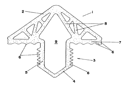
FIGURE 1 is a ceoss-section, illustrating the shape of the elastomer strip;
FIGURE 2 is a perspective view showing the end of the strip with a valve; and
FIGURE 3 is a cmss=suction of the scaling element insert~od in a joint.
As shown in these drawings and the details thercvf, but especially in Figure
l,
an embodiment of the invention is characterized by the
fact that it includes an arrow-shaped elastomer strip (1)
consisting of a triangular head (2) and a rear insertion
section (3), which occupies about a third of a base (7)
of said head and the rear wall of which
ends in a wide angle like the two sides of a roof (4), while the lateral walls
(~ are externally
corrugated or ridged (6), an arrangement that is also found on the external
surface of the base
('~ and the lateral seCbioas of the head (2), which, along with the insertion
suction (3), have
various longitudinal hollow sections defined by various interior walls (8)
which are positioned
at different angles to one another and to the lateral wars of the strip, thus
forming an actual
chamber (9), also in the shape of an arrow, for insufflation and,
consequently, one end of the
strip (1) is closed off or appropriately sealed, while the other (Figure Z) is
fitted with a cover
(10) and a valve (11), which is all that is necessary for the strip to be
inserted and positioned
within a given joint; as illustrated in figure 3, where it is shown that air
is pumpod into the
interior, so that the walls of the elastamer strip press against the adhesive
applied to its sides,
where said ridges considerably increase the area of adhesion and prevent the
strip fmm moving
while said adhesive cures.
The recess (R) in the concrete is provided in plan so that the strip remains
confined within this space, and when hydraulic pressure is exerted, it will
encounter lateral
resistanet and will be deflected against the interior walls, thus preve~ntitig
traetive stress on the
3
i 1
CA 02106352 2004-04-27
79091-1
concrete. It is r~nell known that concrete has little tensile strength and is
approximately IO (tenj
tunes more resistant to compression.
When hydraulic pressure is exerted, the strip is deformed and presses against
the
edQea of the concrete, distributing the compressive forces and providing a
bettex perforrna~nce
of tha system.
Moreover, the strip absorbs stnrcturai movements caused by traction,
compression, shearing, uneven sealing and rotation.
As indk~ted, based on the foregoing explanations and iIlustradons, the object
in
question, "F~cpansion joint xaling element,' fully satisfies the criteria xt
forth herein,
since it combines and modifies known elements is a new way or in a different
arrangement of its component pants, thus increasing ics efficiency, improving
its perforn~ance
and making it easier to use.
4