Note: Descriptions are shown in the official language in which they were submitted.
3 ~ ~ ,
Patent ~9
A Method for ~nplementing Selectable --
Protective Relay Functions
BACKGROUNDOFTHEINVENTION
Traditionally, electromechanical or single-function solid-state relays have been designed for
use in electric power systems to meet the requirements of synchronous generator protection. Major
advances in digital technology and signal-processing algorithms make it now possible to integrate
many protective functions into a single digital relay, providing an economically viable aiternative for
the protection of the generator. In addition, digital technology provides improved performance and
greaterflexibility.
In earlier prior art digital protective relays, the microprocessor simply replaced discrete relay
logic and the voltage and current signals are processed by many analog components. The performance
of these prior art protectlve relays depends on the accutacy of analog components used and is subject ; ~;
to dc offsets which drift with temperature, supply voltage changes, or aging. In later digital protective
relays, the microprocessor both processes the signals and performs the logic, thereby eliminating the
problems associated with analog hardware and providing a simpler design and better perforrnance.
A prior art multifunction protective relay incorporates many protective functions in a single
relay where an analog signal-processing hardware is replaced with a digitai signal processor (DSP), as
disclosed in U. S. Pat. No. 5,224,011 issued to Murty V. V, S. Yalla, et al. In this patent, the voltage
. . r : :, .. , .: , ~:
6~
. . ,
and current input signals of the relay are modelcd as sinusoidal signals which may be affected by dc
offset and harmonic components. These voltage and current input signals can be charac~erized by
various parameters. namely, rms value, peak value nnd frequency of ~he fiundamental frequency
component. The~e-various parame~ers of the input signals are estimated using digital signal-process-
ing algorithms.
Relays for protection of synchronous generators connected to electric power systems take
into account the types of faults and abnormal operating conditions ~hat may be present at the gener-
ator and the connected power system. Many such faults can be detected by sensing the generator
terminal voltages and currents.
' : -
SUMMARY OF INVENTION ~~ :
The present invention is directed to providing an improved method for implementing protec-
tive relaying functions for five of these faults and abnormal conditions. More specifically the inven-
tive method provides protective relay functions for the following~
1) Volts per Hertz
Whenever the ratio of the voltage tp the hrequency tvolts/Hz) applied to the terminals of the ~ ~
generato~ exceeds 1.05 pu (on the generator base), saturation of the magnetic core can occur and stray ~ ~:
flux can be induced in components not designed to carry fiux.
In this situation, severe overheating can occur, causing damage to the generator. Over excita-
tion most often occurs during start-up, when the generator is operating at reduced frequencies or
during complete load rejection. A similar problem can affect transformers. ;
2) Loss Of Field
Partial or complete loss of fleld can cause the synchronous generator to operate as an induc-
tlon generator and draw heavy amounts of reactive power from the power system. This can cause
mechanical damage to the generator rotor; also, high currents in the stator can cause stator damage.
Loss of field can also cause the system voltage to sag, causing system instability and possibly
cause an electrical system shut down.
3) Phase Distance
The phase distance function provides back-up protection for the synchronous generator, the
unit transformer and the connected power system for phase to phase and three phase faults. A simple
`` 21~3~7
overcurrent relay may not provide adequatc protcction sincc Ihe gcnerat()r stcady sta~e short circuit
current can be below the full load rated currcnt ol Ihe generator.
The phase distance function, which operates by mcasuring the impedance to the fault location
and hence the distance, performs properly irrespective of the syslem voltage ~nd fault current magni-
tudes. The impedance measurement is not alfccted by any changes in the voltage magnitude.
4) Ground Differential Protection
Generator ground faults may occur due to insulation deterioration of the stator winding.
When the generator is grounded through a low impedance, ground fault protection may be provided
by the phase differential function depending on the fault level and differential relay sensitivity. ~ ; -
Higher sensitivity and fast relay operation for ground faults can be obtained through the use of an
additional zero set~guence differential (87GD). -
5) Overvoltagé .
Generator overvoltage conditions may occur due to a load rejection or excitation control
failure. In case of hydrogenerators, upon load rejection, the generator may speed up and the voltage
may reach high levels, causing insulation damage, without necessarily exceeding the generator's V/ ~ ;
Hz limit. The overvoltage hunction S9 is, therefore, generally used in addiaon to V/Hz protection.
DESCRIPTION OF THE DRAWINGS
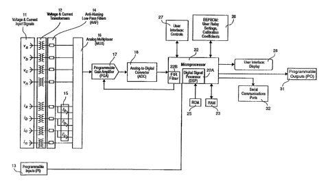
Figure I is a block diagram showing the functions and components required to implement the
inventive method,
Figure 2 is a schematic diagMm showing a typical application of a protective relay using the
Inventive method to provide generator protection; Figure 2 shows standard device-function numbers
as defined by the Amerlcan National Standard Institute (ANSI) C37.2-1987 for the protective relay ~ :
element functions,
Figure 3 depicts the sampling technique performed by the inventive method to accurately
determine volts per Hertz magnitude,
Flgure 4(a) shows the magnitude versus frequency characteristic of the input transformers
and anti-aliasing filters on the volts per Hertz calculations,
Figure 4(b) illustrates the inventive method of approximating the magnitude characteristic
i , ' ~ ~1 ` ' ' ; ;~ '
~ '21~3~7
using a piecewise linear curve.
Figure S(a) shows the parameters ot' Ihe Trapezoidal Finite Impulse Response (FIR) f'ilter,
Figure S(b) is a graphical representa~ion of ~he ~'requency response ol Ihe FIR l'ilter.
Figure~S~c) depicts the impulse response of the FIR filter,
Figs. 6(a) and 6(b) are the two families of invcrse-time curves that are implemented by the
inventive method for the V/Hz function~
Figure 7(a) shows an example of the ot'fsct mllo characteristic that is implemented by the
inventive method for the loss-of-field function,
Figure 7(b) shows the effect of the fixed direcaonal element on the offset mho characteristic
that is implemented by the inventive method for the loss-of-field function,
Figs 8(a) and 8(b) illustrate two examples of the operating characteristics of the ground
differential function implemented by the inven~ive method, ' '-~
Figure 9 shows the mho characteristic that is implemented by the inventive method for the ' ~ ''
phase distance function,
Figure 10 is a table depicting the impedance calculations for direct-coMected and delta/wye-
connected generators performed by the inventive method for the phase distance function,
Figure 11 Is a table showing the possible combina~ions of the inventive programmable inputs
and outputs.
DESCRIPI~ON OF THE ~1VENTION
Refer to Figure 1, shows a block diagram similar to that disclosed in the above cited Yalla et
al patent 5,224,011, which discloses functional elements which can utilize the inventive methods
described herein. In Figure 1. eight main inputs are the voltages (V~" Vb, Vc and Vn) and currents (l
Ib, Ic and In) of the three phases and neutral at the generator terrninals, collectavPIy numbered 11.
These inputs are proportionally scaled and isolated by the voltage transformers (VTs) and current
transformers (CTs), collecavely numbered 12. The Anti-Aliasing Filters (AAFs), collectively labeled
14 filters slgnal harmonics and noise and prevent imptoper assimilation or interpretation of high
frequency harmonics by the microprocessor 22. The additional current inputs for each of the three
phases, collecavely labeled 15, provide accurate measurements of low level current signals. As is
known, the analog multaplexer 16 sequentially accepts the scaled voltage and current signals and
3 r~ r~ ~
routes them lo the programmable gain ampliller (PGA) 17. n-e gain ol ~he P(iA 17 is adjusled ror
each phase current input by the microproccssor 22 to allow tor differenccs in the impedance reach
setting for lhe phase distance hunction, described hereinarter. The output of the PGA 17, represenang
in time sequence the eleven measured parameters, is scaled to make it compatible with the well
known analog-to-digital converter (ADC) 18. ~ ~ -
The microprocessor 22 contains the ~ligilal signal processor (DSP) 22A, which performs the
many calculations required in the limited time available. Fundamental to the inventive method is the ~ ~
determination of the rms value and the fundamental frequency of the voltage signal. -
The DSP 22A acquires the digitized samples of the voltage and current signals 11 (a total of
eleven) from the ADC 18. A digital finite impulse response (FIR) filter 22B is used in the inventive
method described hereinafter to filter each of the three-phase voltage signals. The DSP 22A then ;~
determines the frequency of the three-phase voltages using the inventive methods described hereinaf-
ter. The determined frequency is used to correct the magnitude errors in the AAF 14 and voltage ~ -
, . - . .. ..
transformers 12 that occur when the frequency is not at or near 60 Hz (off-nominal). The DSP 22A
determlnes the values of Ihe three-phase voltages for the overvoltagc and V/Hz îunctions. The DSP
22A then calibrates the gain errors at nominal frequency of each of the eleven channels using the
calibration coefficients (stored In EEPROM 26) that were precomputed using a selected calibration
. . . . ..
program. The DSP 22A computes voltage and current phasors using a discrete Fouder transform
algorithm. The phase angle inaccuracies due to sampling skew, CTs, VTs and anti-aliasing filters are
calibrated from the fundamental frequency phasors. The calibrated phasors are then used to compute
the Impedance for the loss-of-field and phase distance functions. The calibrated phasors are also used ~ ~ k
for the ground differential function 87GD, described hereinafter. The DSP also implements the mho
charactedstics for the Loss-of-field and Phase Distance funcaons, and the Inverse-time curves for the
V/Hz function, whichwill bedescribedhereinafter.
The two user interfaces, blocks 27 and 28. are for operator input of settings and for feedback
to the operator of the relay status.
When the microprocessor 22 has determined that a particular parameter has exceeded a
setting for a preset time delay, and if the particular function is not blocked by one of the program-
mable inputs t3, to be described hereinafter, a signal is sent to instruct the inventive programmable
outputs 3 I to take further action, such as opening or closlng the approprlate output contact.
~1063~7
.
The serial communications ports 32 are used lo program the ~;ettings in the relay or to down-
load information from the relay via an appropriate communications link.
The protective relay functions implemented by the inventive methods for protection of
generator 69 are~hown in Ihe simplified one-line diagram of Figure 2. The standard device-funcaon
numbers included in Figure 2 are as defined by the American National Standards Institute (ANSI)
C37.2- 1987. Note that the protective relaying function that are discussed by the inventive method are
shown as shaded circles in Figure 2. In addiaon, the funcaons depicted as white circles are typical1y
required for protecaon of the system shown in Figure 2.
The V/Hz funcaon 24 is applied to protect the generator 69 from the overheating that can
occur when the raao of voltage to frequency at the generator terminals exceeds a safe value. The
implementation method for the V/Hz function 24 incorporates two definite time setpoints, and four
families of inverse-ame curves. The user selects one of the curves. to be used alone or in conjuncaon
with a definitc ame setpoint, to match the specifications of the protected generator. V/Hz protection is
especially required during generator start-up and shutdown (i.e., not connected to the system), where
the V/Hz measurement may need to be accuratc from approximately 2 to 120 Hz. Some applicaaons
require that VMz protection be applied while the generator is on-line (connected to the associated
system). Note that In a preferred embodiment, the range of 8 to 80 Hz was chosen for pracacal
reasons, including keeping down the size and cost of the microprocessor 22. However, the Inventive
method can easily be extended to 2 to 120 Hz by using a more powerful microprocessor.
The Three-Phase Overvoltage function 59, shown in Figure 2, is used to protect the generator
69 from overvoltage conditions. Funcaon 59 needs to be accurate over a wide frequency range,
especially in the case of hydro generators where operaaon at high frequencies is possible. Two
dennite-time setpoints, such as two Independent magnitude setangs and two time dial setangs can be
selected to trip the generator or sound an alarm.
Another protective funcaon that is implemented by ~he inventive method is Loss-of-Field 40,
shown In Figure 2. The field is supplled to a synchronous generator to provide air gap flux. Reduced
or complete loss of fleld can cause loss of synchronism. instabillty and, possibly, damage to the
generator. For these reasons, a loss of field relay is applled to protect the generator and associated
system from loss of fleld. Thus, the generator will be tripped off-Une when the relationship between
the alternaang voltages and currents indicates that a loss-of-field condition has occurred.
The Ground (Zero Sequence) Dirfercn~ial lunclion (shown in Figure 2 as 87GD) provides
ground fault protecaon for genera~ors grounded Ihrough low-imped.~mce by operating on zero se-
quence current differential. In applications where a zero sequence currcnt sourcc is available. i.e.. for - -
grounded power systems, a direcaonal element, can be added to the ground differential function
87GD, which will be described herinafter.
Function 21 Phase Distance, shown in Figure 2, can be set by the user to provide backup ~ ~ .
protection for phase-to-phase and three-phase faults in the generator. power transforrner and intercon- ` ~ - -
nected system. - .~ -
Volts Per Hz Function ~-
Refer now to one function implemented by the invenave method: the Volts per Hertz func-
aon 24. In the early implementation of the V/Hz funcaon. analog and digital circuits were used to
extract the magnitude and frequency on all three phases of the alternaang current supply to the relay. -
Prior art relays with this circuitry operated well but suffered from errors and temperature instability~
as well as reliability problems due to the complexity of the circuitry required.Several prior art systems use a processing method utilizing a discrete Fourier transform
(DFT~ to obtain both the magnitude and frequency of the alternating current signal. However. the
accuracy of the DFT Is affected by deviation of the input signal frequency from its nominal value
(typically 60 Hz). When the generator is connected to the system (on-line), the local load and large
intercoMected system will tend to limit frequency deviation from 60 Hz, stabilizing typically be-
tween 59 and 61 Hz. A relay implementing the VMz function in software using DFT would work ;~
well while the unit was on-line, since the deviation is fairly small. However, once the generator is
disconnected from the system, the machine may experience frequencies well outside this range. Here
the prior art method for calculating V/Hz would give large errors in the estimation of frequency and
voltage magnitude.
One prior art method used digital phase-locked loop concepts to automaacally change the
sampling frequency to an integral and constant multiple of the signal frequency to increase the
accuracy of the DFT for frequency signals that are outside a nominal frequency of approximately 59
to 61 Hz. Thus to make the DFT esUmates accurate, the sampling rate of the prior art method is
changed to be always 16 times the input frequency. For example, if the input frequency is 10 Hz, the
sampling rate is 16 times 10 or 160 Hz. At 60 Hz, the sampling rate is 16 times 60 or 960 Hz. With
this technique. it is difficult to achieve accuracy over a wide enough firequency range due to imple- -
mentation limitations, to fully protect the generator. Also when the sampling intervai is variable, the
integral timers that are needed ~o obtain the inverse time char~cteristics are difficult to implemcnt. } ~ - -
since the integra~on period is variable and depends on the input signai fre luency. The prior art thus
discloses a frequency domain approach which uses DFT.
In contrast to the prior art. the inventive method uses a simple time domain approach to
extract the V/Hz information, thereby providing accurate voltage and V/Hz measurements over a
wide frequency range such as from 2 Hz to 120 Hz.
Referring to Figure 1, the voltage signals are filtered using 2nd order passive low pass filters
to limit the noise and harmonic components. The filtered signals are multiplexed and then sampled at
a constant sampling interval (~T). The sampled signals are converted to digital numbers using an
analog to digitai converter. Since the low pass filter is of 2nd order, small components of harmonics
and noise may still be present in the sampled signals. These unwanted components should be re-
moved before the samples are used for frequency calculation. In order to filter the remaining noise
and harmonic components, a digitai anite Impulse Response Filter with a sharp cut off is imple-
mented in the DSP 22A. The filtered samples are represented by vk where k = 0... m + 1, as indicated
in Flgu~e 3.
The inventive method measures the time period between the two selected zero crossings and
determines the fundamental frequency time period of the voltage signal as follows:
The time period of the fundamental frequency signai
time period between two selected zero crossings
=2x
(number of zero crossings between the selected zero crossings - I)
In Figure 3, the dots along the sine wave are magnitudes of the voltage samples, represented
by vO, vl, v2, v3...vm+l. The T, shown in Figure 3 is the elapsed time from Zero Cross 1 to Zero
Cross 2. Slnce the value of T is no longer a constant and no longer an integral number of samples at t
frequencies other than 60 Hz, it is obtained through interpolation as follows. Referring still to
Figure 3, the inventive method involves determining the two successive negative-to-positive going
transitions of the sine wave. this is represented by the portions of the wave from vO to vl and from
Vm to vm +I)
-8-
, ...
3~
Since the samples arc spaced at a constant intcrval ( ~T), one can nn(l the period between
samples vl, and vm as:
(m~ T (2) ; ~;
Wller~: ~T is Lhe sarnpling intcrval and m rcprcsenls the lotal number of samples between ~ ;
Zero Cross I and Zero Cross 2.
The time period from Zero Cross I lo vI ~0 in Figure 3, and the time period from vm to Zero
Cross 2, ~1, can be found using linear interpolation as follows: ~
(Vl - Vo ) ~ ~i
and
m )~T (4)
The above equations are good approximations of the sinusoidai voltage waveform near the
zero crossings; since, when the sine wave is not distoned and the angle is close lo zero, it is well
known that:
sin~ O = l (S)
That is, the sine function is linear near the origin or Zero Crossing. ~ :
A Finite Impulse Response filter 22B. described hereinafter, is incorporated in the inventive
method to filter out noise and distortion so that the calculations using equations (3) and (4) are
performed on undistorted sine waves.
Now the time period T, shown In Figure 3, is given by:
T=~0+~1+(m~ T (6)
The totai number of Zero Crossings between Zero Crossing I and Zero Crossing 2, including
Zero Crossing I and Zero Crossing 2 Is 3.
Tlme period of the fundamental frequency voltage signal is:
T
x2 =T
(3-l)
Now the firequency "f" can be determined as ~ = I/T.
The technique is based on c~culating the nns value of the signal using the following equa-
tion.
Vnns = ~ (7)
k=l
Where T and Vk are shown in Figure 3.
Now the V/Hz is given by
V/Hz, -- or
(8)
= (V~n,s)(T)
Refer now to Figure 4(a), which is useful in explaining the effect of the input transformers
12 and anti-aliasing filters 14, shown In Figure 1, on the voltage magnitude calculation. The voltage
magnitude versus frequency characteristic of the input transformers and anti-aliasing fllters used in
microprocessor-based relays are usually of low pass type. Fig 4(a), which is only an illustrativc
example and not drawn to scale, depicts that the gain of the input circuit is not constant over a fre-
quency range of interest, which can adversely affect the timing characteristics of the V/Hz function
24. The curve shown in Figure 4(a) shows higher gains below 60 Hz and lower gains above 60 Hz
than the nominal gain at 60 Hz. Therefore, in the inventive method described herein, the magnitude
characteristic is approximated using a piecewise linear curve, (see, for example, the straight line
labeled Piece #1 in Figure 4(b)). The coefficients corresponding to the straight line segments are used
In real time to correct the errors introduced in the input circuit by the input transformers 12 and anti-
allasingfilters 14. I ;
Refer now to another feature of the inVentiYe method. Since the V/Hz measurement relies onthe zero-crossing detection procedure, described hereinabove, it may be affected by errors due
to
- 10- ''; '"
,
:^`
' ' ' ,
w~vet'orm dislortion and noise. As stDted earlier, hl ordcr to minimii~,e Illese errors. ~c vollagc signDls
should be filtered.
In the present invention. the voltage signals are filtcred using tl digit~ Finite Impulse Re~
sponse (FlR) low~-pass filter, 22B.
There are various digital filter design techniques available, and ~ simple trapezoidal approxi-
mation is used in the present invention. The char~cterislics ol the FIR filtcr, 22B ~re shown in Figure ~ , -
5(a) and are defined as:
Sampling period T= 1/(60)(16) sec. = 1041.667 microseconds
Pass band frequency P = (2~)(100) = 628.32 radians/sec. or 100 Hz
Cut-off frequency C = (2~1)(200) = 1256.64 rsdians/sec. or 200 Hz
Q =--= 942.4 radians/sec.
~ =--= 314.16 radians/sec. (9)
The FIR fllter is described by the following equation:
N-1
YK = ~;hnXK n (10)
n=0
Wllere:
YK jS the output sequence
N is the filter order
hn are the filter weighting coeff~cients
XK,n is the input sequence
A 17th order filter, is chosen in order to obtain a sharp cut-off in the frequency response. The
frequency response of the filter is shown in Figure 5(b). The corresponding Impulse response is glven
In Flgure 5(c). It can be seen from Figure 5(b) that the filter sharply attenuates harrnonics and noise
components above 120 Hz. Also the sharp cut-off of the tlller is a~hieved ~lue l~ Ihe 17th order Illter
design.
Once the VMz measurement is oblained, it is compared with ~ user selected threshold value.
If the V/Hz is ab~ve the threshold value. two definite time and four families of inverse time character-
isacs are implemented by the Microprocessor 22. These curves can be used to match the generator
and/or transformer damage curves. Thus the inventive method can be applied to both generator as
wel1 as transformer protection applications. ' -,
One of the Curve Family which is used in the industry is shown in Figure 6(a) and it is
obtained by the following equation:
t = 0~0031; (I l)
A second Curve Family which is also used in the industry is shown in Figure 6(b) and it is
obtain by the following equation:
(11 5+2.5K)- M
t - e 4.8858 (12)
The other Curve fam~lies which are implemented in the present invention are obtained by the
following equations:
(1 1 3.5+2.5K)-M
t = e 304 (13)
and
(108.75+2.5K)-M
t = e 2.4429 (14)
Wl~ere:
t Is the operating ~ime of the relay in minutes
K is the time dial setting
M is ~e V/Hz in percent, M is 1()()% at nominal voltagc and nominal frequency
During an overexcita~ion condition of the generator, Ihe V/Hz measurement may change as
time passes. and dircct application of equalions (I l) through (14) could result in erroneous tripping
times. To avoid possible timing elTors, the inventive method uses the integral of the V/Hz during
overexcitation conditions, as follows: ~ -
t ~-
f(M)dt 2 C (15)
t=to
WJlere: functionf(lvl) and constant C depend upon the type of curve and the time setting
selected.
The integration process begins at t=to, which is the initial time at which the V/Hz exceeds the
pickup value with an initial integrated value of U0. Thc digital implementation of the above equation
represenang the output of the integrator at Kth instant Uk is as follows:
UK UK 1 +f(~ )K (16)
W/lere: (M)K is the V/Hz at the Kth instant.
Thus, the protective relay using the inventive method operates when the running sum reaches
a threshold value of:
C' C
= Ti (17)
Wllere: T~ is the integration time period, which is chosen in the present invention as one
cycle on 60 Hz basis (16.67 ms). , l~
The integrator has maximum and minimum limits of C' and Zero respectively.
Implementation of equation (16) shown in Figure 6(a) is straightforward. Implementation of
~a~35~
,__
...
equation ( 12) shown in Figure 6(b) and equalions ( 13) and ( 14) requires conlputati()n of exponential
function.
In the inventive method described hercim the e function is approximated as follows:
eX 2,Y / loge2
_ 2l.4427x
- (18)
= 2,Y
W71ere: X '- 1.4427X
Now 2~ can be wri~ten as:
2 ~' 2('r~ +'rf )
= (2 ri )(2Xf ~ (19)
Wllere:
Xi is the integer part of X ', and
Xf is Ihe fractional part of X '.
Implementation of 2~YI is accompiished with simple shift operations. and 2Xf is approxi-
mated as follows:
' .
2'Yf = C0 + C1Xf + C2Xf2 + C3Xf3 + C4Xf4 + CsXfs (20)
Equation 20 is rewritten to reduce the computational burden from 15 to five multiplications
on the microprocessor, as follows:
2Xf = (CO + Xf(Cl + Xf(C2 + Xf(C3 + Xf(C4 + XfCs))))) (21)
The equations 20 and 21 are identified and give same results.
I '
Wllere:
CO = l.o
- 14-
Cl = ().693147
C2 = 0.24()2264 . - '
C3 = 0.0555036
- 1~4 = 0.009615978
C5 = 0.00132~240
As an example for Equation (12), shown in Figure 6(b), the integration would be:
MK
UK = UK 1 + e4-8858
X~ Xf (22)
= UK 1 + (2 )(2
W~lere:
Xi istheintegerpartof 4881C8xl.4427
Xf is the fractional part of 4 881( 8x1.4427
115+2.5K
C = e 4.8858
.,
C
C =16.67x10⁻³
K is the time setting shown in Figure 6(b).
The inventive method also implements a linear reset characteristic. which closely emulates
the generator cooling characteristics. This is achieved by subtracting a constant from the integrai Uk
when the V/Hz is below the pickup setting. This maices the relay trip the generator faster if the
generator has not cooled sufficiently from a previous V/Hz excursion.
Implementation of the VlHz function by the inventive method in a microprocessor accurately
and reliably protects a generator, both on- and off-line, since:
The voltage magnitude and frequency are accurately measured and the V/Hz accurately
estimated up to 200% (twice the nominai vaiue) over a wlde range of frequency from 8 to 80 Hz. The
frequency range can be e~sily wid~lled by increasing the number Or bils selected for the time period
representation.
The method implemented works well even at very low voltage magnitudes. The variable gain
characteristics o~he voltage transtormers and anti-aliasing filters over the desired firequency range of
interest. which create timing errors. are corrected by the inventive implementadon technique. Aiso,
the Digital Finite Impulse Response filter enables Ihe accurate and reUable rejection of harmonics and
noise components above 120 Hz.
By selection of definite-time settings and four families of inverse-time curves, as well as the
linear reset characteristics implemented by the inventive method. the user can closely duplicate the
generator and transformer protection specifications.
Over Voltage
To adequately protect the generator against overvoltage conditions? the overvoltage funcaon -
59 should also be accurate over a wide frequency range. Since the time domain approach is used in
the inventive method to determine the voltage magnitude as discussed above~ function 59 is accurate
over a desired range of frequency range of from 8 Hz to 80 Hz. Two voltage magnitudes, each with a ~;
separate ame delay, are implemented in software by the inventive method.
Loss Of Field
Refer now to another feature incorporated in the inventive method: Loss-of-field protection
function 40, aiso as shown in Figure 2. Several commercially available prior art impedance relays
with an offset mho characteristic have been applied to generators to protect against damage that can
be due to loss of the generator field. These relays use phase-to-phase voltages and currents to obtain
the impedance for the offset mho characteristics. However, these measurements can still be affected
by frequency changes.
Refer now to Figure 7(a) and 7(b) where the characteristics of an impedance relay are plotted
on a rectangular coordinate system, known as an R-X diagram, with resistance (+R) plotted on the
absclssa and reactance (+X) on the ordinate. The "operate to trip" portion of the charactedstic usually
Is described by a circle of Impedance vaiues. The traditional characteristic normally used for loss-of-
lleld protection is ca11ed an "offset mho" and is implemented by the inventive method described
hereln. To be compatible with existing industry practice, the inventive method described duplicates
- 16 -
~ .
two user-selectable "operate lo trip" circles (see 41 and 42)~ cach wi~ a sclcctable time delay, select-
able diameters. and selectable degree of offset rrom thc abscissa for each circle (sec 43). as shown in
Figure 7(a). An impedance relay with such an offset mho characteristic will only operate to trip Ihe
generator olf-line, after the appropriate time delay, for impedance values wilhin "Circle Diameter #I"
(see 41) or "Circle Diameter #2" (see 42) shown in Figure 7(a). The dcgrce of orfset (see 43) for bolh
circles 41 and 42 has been selected as desired.
Loss-of-field 40 protection works well when the mho characteristics are offset from the
origin, as shown in Figure 7(a). so that tripping of the generator only occurs in the 3rd and 4th
quadrants. However, when loss-of-field relays are required to coordinate with generator capability
curve and minimum excitation limit curve, the offset mho characteristic needs to be set to include the
origin, as shown in Figure 7(b). However; when the origin is included, the operate to trip characteris-
tic will be in all four quadrants, which opens up the possibility of misoperations during power swings
and fault conditions. ~-
Refer to Figure 7(b). which shows Circle Diameter #1 (45) with one degree of offset (47
Offset #t) and Circle Diameter #2 (46) with a different degree of offset (48 Offset #2). Note also that
Clrcle Diame~er #2 now includes the origin. In order to prevent relay misoperations during power ~
swlng and fault conditions, a directionai element 44, is Implemented in the inventive method, which ~ ~;
prevents tripping In the Ist quadrant and limited portions of 2nd and 4th quadrants. The microproces-
sor 22 will only send a signal to the output contacts if the impedance is within the circles and below ~ `
the directional element.
Assuming voltage and current signals at the terminals of the generator are sampled and
brought into the microprocessor through an A/D converter 18. as described previously, the calcula-
tions to implement the Loss-of-Field function 40 comprise the following steps: -
1. The digitized samples are processed with a prior art discrete Fourier transforrn (DFl')
algorithm to obtain estimates of the fundamental frequency voltage (Va~ Vb and Vc) and current (IJ Ib ~:
and lc) phasors.
2. The positive sequence voltage (Vl) and current (Il) phasors are determined.
3. The positive sequence impedance (Zl) is then determined by complex division of the
voltage and current phasors.
The positive sequence impedance for the Loss of-Field function 40 is determined using the
- 17 -
t3 7
following rela~ions for dilferent voltage translormer contlguralions, as seleclcd by lhe user rOr a
par~icular installation.
Line-to-~round VT Zt = I (23)
Line-to-Line VT zl = VlL ~ (24)
Where:
Zl is the positive sequence impedance
VIL N is the positive sequence line-to-neutral voltage
VIL L is the positive sequence line-to-line voltage
Il is the positive sequence current
4. The positive sequence impedance is compared with the offset mho charactedsticselected by the user to determine if the apparent positive sequence impedance is inside the "operate to
trip" portion; i.e., within "Circle Diameter #I" or "Circle Diameter #2". ~ ;
5. If the impedance is found to be inside either circle, the microprocessor 22 sends a
signal, after the appropriate time delay selected, that is used to activate an output contact to take
further actlon, such as tripping the generator off-line or controlling the field.
The inventive method also incorporates voltage control and frequency control features. When
undervoltage control function 27 is selected. the measured positive sequence voltage magnitude must
be less than a user selected setting in order to trip the generator. Similarly, when the frequency control
function 810 is selected, the loss-of-field function 40 is prevented from sending a trip signal to the
output contacts when the frequency is above a user selected value. The setpoint ranges selected in one
embodiment of the installation for voltage control is S to 200 V and for frequency control the setpoint
range is 60.05 to 67 Hz.
The use of positive sequence impedance in the inventive method; instead of phase-to-phase
impedance, as has been accomplished in prior art; has several advantages. First, the use of positive
sequence voltage and current phasors provides a filtering effect on the determined impedance during
unbalanced conditions of the generator.
Secondly, the effect of frequency variation (50 Hz to 70 Hz on a 60 Hz base) on the offset
- 18-
' ' ' ""~
.
- ~0~3~7
mho characteristic used for the loss-of-t'ield fiunction 40 is virlually eliminated when posilive se-
quence phasors are used to determine the impedance. The vultagc and current phasors. determined on
an individual phase. oscillate during off-nominal firequency operation of the generator. These oscilla-
tions retlect on'tl~e-determined impedance giving rise to inaccuracies in the relay operating character- ~
istic. However, when positive sequence phasors are used in the inventive method. the oscillations ~ `
cancel out. giving a stable and accurate impedance estimate. which is used to implement the loss~f-
field function 40.
Ground Differentia'i ~ -
Another function implemented in the inventive method: Ground Differential 87GD, also
shown in Figure 2. During ground faults, the differential current Id, which is the difference between
the triple zero sequence current 3l0, and the neutral current In~ iS determined by the microprocessor as
follows:
ld = (11 +Ib +Ic) ~In . .. ..
Id = 310 - In (25)
wllere~ b and Ic are three phase currents and In is the neutrai current.
In the above equation Lhe currents !d~ Ib~ Ic and In are all phasors deterrnined using a DFT. '';
Often, the current transformers (CTs) measuring the phase currents may not have the same
turns ratio as the neutrai CT. This creates differentiai current during zero sequence unbaiance of the
system. To solve this problem, prior art methods use an auxiiiary CT in the neutrai CT circuit to
correct for a ratlo inequality. In the relay implementing the invenave method, the ratio inequaiity for ; ;
a particular instailation, which the user inputs to the relay, is digitally corrected in ~he microprocessor
22 by incorporating a CT ratio correction factor. Thus eliminating a need for an auxiliary CT. The
CT ratio correction factor Rc, used in the method, is defined as:
~ - '
R ~RalioofLine-sidephasecrs)
' ~ Ralio of Neu~l CT (26)
For example, if the line~side CTs have a ratio of 3000/5, and the neutral CT has a ratio of
600/5, then:
19_ :
, ,.'.'','',',",'`.'''""', ~",' :'
Rc= (3000/5) = 5 00 (27)
Now the ground differential function 87GD is implemented by determining the difference
between the corrected triple zero sequence current. Rc3~o, and the neutral current~ In: ~ -
Id = Rc3~o - rn (28)
.
The magnitude of Id iS ihen compared against the user se.tings, and if Id is above ihe setting
microprocessor 22 will send a signal calling for further action to be taken, such as generator tripping.
In some cases setting the differential function 87GD becomes a problem due to several
reasons, such as when the CT ratios are too far apart or due to saturation of CTs during external fault
conditions. In the present invention a directional differential function is provided to overcome the
above problems. In this case the relay responds only to faults in the generator winding but not in the
system. This scheme requires that a zero sequence source be present in the system. In the inventive
method, the directional function of 87GD determines:
Id =~3IOInCOs~ (29)
Where ~ is the angle between the triple zero sequence current and the neutral current.
Figure 8(a) illustrates the directional characteristic for the Ground Differential function 87GD
that is incorporated in the inventive method. Taking In as the reference, the microprocessor 22 will
call for a trip operation if Id is above the user setting and 3 Io and In have opposite polarities, i.e., if
3IO is inside the shaded portion of Figure 8(a), which is the case for faults in the generator. Operation
is blocked when 3 Io and In have the same polarity, i.e., if 310 is inside the non-shaded portion of
Figure 8(b), which wou]d occur when there is a fault on the external system.
There are two advantages to implementing the directional ground differential function 87GD
In this manner. First, implementation of a CT correction factor is not required, and the function works
well even wlth unequal CT ratios, and secondly, during phase-to-phase fault conditions, the possibll-
- 20 -
~10~357
,
ity of the l'uncdon misoperaLing. even with CT saluration. is minimized.
Ph~se Distance
Phase distance function 2 l . shown in Figure 2. is also implemented by the inventive method.
Ret'er now to Figure 9~ which shows an example of a mho characteristic on an R-X diagram for the
Phase Distance function 21. User settings for a diameter of the circle 51 and system impedance angle
53, as well as a definite tirne delay, are implemented in the method. In Figure 9, the user has selected
setdngs that allow funcdon 21 to protect the generator 53, unit transformer 54 and a portion of the
connected transrnission line 55. The mho circle can also be offset from the origin in either direction.
An offset setting of the mho characteristic aliows the relay to protect in the forward direction, reverse
direcdon or both direcdons.
If lhe transformer 54 is connected in delta/wye configuration and the phase distance function
is set by the user to provide backup protection for transmission system faults, then the high-side
voltages of the transformer are required to sense the correct impedance. In prior art, the high-side
voltages of the transformer are obtained by using auxiliary voltage transformers external to the relay
In the inventlve method. the high-side voltages are determined by the microprocessor 22 using the
generator terminai voltages, thereby eliminating ~he need for externai auxiliary voltage transformers.
In the inventive method, the following steps are performed for the phase distance function 21
First, determine the voltage (VA~ VB~ VC) and current (IA~ IB and ic) phasors using a DFT.
Secondly, determine the apparent impedances as given in the table of Figure 10. In the table
of Figure 10, select the appropriate column for calculation of the impedance depending upon whether
the generator is directly connected to the system or it is connected through a delta/wye transformer.
The above determined impedances are compared by the microprocessor 22 to the mho relay
characteristic. If the impedance is found to be inside the "Operate to Trip" shaded circle, the micro-
processor 22 sends a signai, after the selected time delay, that is used to activate an output contact to
take further action. such as tripping the generator off-line.
Programmable Inputs/Outputs
A programmable inputs/outputs function is implemented in the inventive method as indicated
in tabular form in Figure l l; i'rotective relays have a number of contact inputs and outputs that are
each designa~ed to perform a specific function, e.g., breaker status input, blocking and enable inputs
- 2 1 -
` 21063~7
from other devices, and trip. close or aiarm outpuls.
With the inventive method. any one of thc programmahle inputs (selccted as three inputs in
the present embodiment), also shown in Figurc I as block 13, can block any one or more of the
functions implenrented in the relay. These are labeled in Figure 11 as "BLKI," "BLK2," and
"BLK3." In addition. any function included in the rclay can be programmed to activate any one or
more of the output relays (selectcd as five ou~puts as prescnt embodiment and labeled. "OUTI."
"OUT2," "OUT3," "OUT4" and "OUT5" in Figure 11), aiso shown in Figure las block 31, when the
determined parameters are outside the setting limit~s. Figure 11 can be used to determine the possible
combinaaons of input and output logic assignments for the protecave functions described hereinbe-
fore. The funcaons implemented by the microprocessor 22 using the inventive method are shown in
the rows across the table. The programmable inputs (BLKI through BLK3) and outputs (OUTl
through OUT5) are shown in the columns of Figure 11. The table is set up as if a user has filled in the
circles as a record of how the inputs and outputs are assigned. A blackened circle under the input
section of Figure 11 indicales that the corresponding funcaon on the left hand side will be blocked by
the presence of contact closure at the block input. A blackened circle under the output section indi-
cates that Lhe corresponding output contact will be activated when an operate condiaon exists on the
corresponding funcaon on the left hand side.
Any of the funcaons in the left-hand column of Figure 11 can be programmed to acavate any
combinaaon of the outputs shown in the five right-hand columns. In a typical protective relay, certain
outputs are rated for tripping per ANSI/IEEE C37.90-1989; others are provided primarily to activate
alarm-type relays. In the example shown in Figure 11. "OUTI" through "OUT3" are rated to trip,
while "OUT4" and "OUT5" are rated for alarms or annunciators.
The programmable outputs can be used to perform one standard method of tripping a genera-
tor called, "sequenaal tripping." When full load rejection occurs (i.e., tripping the generator off-line
under rull load condiaons). the prlme mover can sometimes continue to operate at a fast speed,
causing the generator to go into overspeed, possibly damaging the generator. By using the program-
mable outputs to trip the prime mover first, the load on the generator will prevent overspeed of the
generator. Once the prime mover has slowed down enough to cause a reversal of power, reverse
power relay, as shown in Flgure 2 as ANSI function 32 and described in U.S. Pat. 5,224,011 lssued to
Murty V.V.S. Yalla et al, can detect the reverse power condltion and will trip the generator off-line
- 22 -
,,
..`~
. . ,
--~" 21~6357
using a different ou~put of lhe programmable oulput conl~cl.
Several advantages are apparent from the ability of Lhe method lo program the inpul and
output relays. One is that fewer contacts arc re4uired to be mounted externally, increasing the rclhlbil-
ity of the protect~on scheme. Secondly, whcn associated equipment is changed~ a relay using the ~ -
inventive method can be reprogrammed for the new equipment. incre~sing versatility.
While the inventive method has been particularly shown and described with reference to a
preferred embodiment thereof, it will be understood by those skilled in the art that various changes in
form and detail may be made therein without departing from the spirit and scope of the invention.
1~, ~;.,.
~ ~.
".~
- 23 - ~
, ~
' ~,