Note: Descriptions are shown in the official language in which they were submitted.
~ 7
. . `
Burning provided with means f or mi~ing a combustio~ ai-
f iow with a gaseous liquid or pulverized fuel .
The invention relates to a burner provided wlth means for
mixlng a combustion air L low with a gaseous liquid or
~ulverised fuel, provided with an axially symmetrical
vortex chamber having in its axial flow direction at the
eXit side a tapering down portion a central opening
following by flame room of larger diameter.
US - A - 2 806 517 shows a ~urner of this type, in which
pressurize oil is atomized centrally. In the combustion
lo cone following the tapering down, vortices occur at both
sides of the atomization cone of the oil.
The invention is based on the understanding that a gas flow
with a strong rotation around the flow axis compared to the
~5 axial component, can, with a sudden widening of the flow
diameter, induce a sudden and very strong turbulence in the
flow, in the following re,erred to as 'vortex break down'.
This vortex break down manifests itself in a shatterin~ o~
explosion of the jet while forming very strong local
turbulence which leads to an extremely thorough mixing of
the substances in the flow.
In addition a very stable vor~ex is created in which a very
thoroughly mixed fuel-air mixture can be burnt in a short
pèriod of ~me so that exceptionally low NOx values occur.
The same thorough mixing allows complete combustion with
virtually~ no excess of air. As the tangential component
increases to the same extent as the axial component with
the increase of the gas velocity, blowing off the flame is
~ 30 virtually impossible. Another property of vortex break down
is that an axial counter flow is induced, which in the
invention flows back through the tapering down portion and,
by doing so, forces the substance that is to be mixed
towards the outer side and preferably even against the wall
3S of the tapering down.
- ~ SUIB5TITUTE SHIEET
,- . .
. .. ~ .
.
.. , , ., ~ - .
- . ... ~ . :
2- 2 ~ r~
Such a vortex breaX dowr, is obtained by a burner according
to claim l.
It is pointed out that th~ tapering down portion can
consist of a material tapering down of the chamber as
defined in claim 1 as well as of air injecting or directing
means giving the combustion air flow an inwardly directed
radial component.
In order to avoid big differences in flow velocity at the
confrontation of this gas flow and the rotating combustion
air flow, wlth this embodiment it will, of course, be
ensured that the gas flow which causes the narrowing has a
rotation motion and possibly an axial movement as well.
While tapering down a jet rotating around its axis, the
energy fed to the jet is being converted into rotation
energy by means of the Coriolis forces. As a result the
ratio between the rotation component, in particular on the
outside of the jet, and the translation component
increases. This results in a fall of pressure in the centre
of the jet, which can lead to underpressure, as a result of
which in principle a flow can be created that is directed
against the axial direction of the flow.
For preference the invention provides that the tapering
down reduces the diameter of the tube to 0.9 - 0.7 of the
diameter pr'ior to the narrowing. Within this range, which
is only preferential, vortex break down can in practice be
achieved with a pressure difference for the thrust of the
jet from 3 to 5 cm of water (300 to 500 N/m2).
It is preferably provided that the tapering down portion
includes at its end an angle with the axis of over 5~
degrees. Herewith it is pointed out that also in case of
acuter angles with the axis at the end of the narrowlng
good results are to be obtained, but that with angles or 50
degrees to about 60 degrees an adequate rapid compression
of the jet can be combined -~ith a short transit time and,
SIJBSTITUTE SHEET
- .
..... . . . .. . . .. . .. . .. .
-~ -3- 2 i ~ 7
therefore, little thrust losses and formation of micro-
turbulence in the rotating flow itself.
With the invention the rotation enforcing body is connected
only to the outside shell of the vortex chamber~ This means
thal the inside area of the ~et, which is the area within
the outside shell, is also made available to the axial flow
of the jet. As a result of which the total section becomes
larger because the cross-sectional area of the outside
shell is smaller than the total sectional area in the
tapering down. This means a decrease of the axial velocity
of the flow and, therefore, an increase of the ratio
between the rotational component and the axial component of
the flow.
In accordance with a further elaboration of the invention,
it is provided that in the centre of a surface closing the
central region of the rotation enforcing body an inlet is
present for a liquid or pulverized fuel, which can move
along said wall unto the exit openings of the rotation
enforcing body. Important is that in the centre of the jet
an underpressure is created with a counterflow near the
axis. This throws the mixing substance towards the back
surface. In the process the strong rotation will contribute
to the fact that, when the mixing substance is a fluid such
as oil, it will move along said surface. By this it is
achieved that the fluid can be carried along to the areas
of the vortex which are located more to the outside, where
the velocity of the vortex flow is high 50 that the liquid
can be atomized.
The liquid or pulverized fuei, however, is subject to the
!j ' ' strongest atomization and mixing when it is thrown off the
edge of the tapering down por.ion and enters the vor~ex
break down area. As a result it is possible to obtain a
very good atomization of oil, which is introduced under a
very low pressure, for instance 5 cm of water.
A further refinement of this is that said surface is
SUBSTITUTE SHEET
1 ~ -4- 2 ~ ~ 6 ~ 7
.. ..
conically widened in the direction of the flow. As a result
- the gravity component, whic~ has its effect on tne ~ixing
substance, is partially compensated by the inclination of
the back surface, which ensures a better symmetrical
discharge Cî the fuel.
. .
~r It is also possible to devise the rotation enforcing body
in such a manner that the flow itself, leaving the rotation
enforcing body, will cause the narrowing. Accordingly, in
this case it is provided that the rotation enforcing body
is devised to introduce a gas flow with besides the
tangential component an inwards directed radial component
around the tube and through the cylinder surface of the
tube. As has been mentioned above, the vortex break down
will occur when the flow section is widened. It is to be
recommended that this widening will be abrupt and that the
flow section for small burners (up to circa 50 kW) will
preferably be enlarged at least five times in relation to
that of the tapering down, and for large ones circa 2.5 to
3.5 times.
The above has been found favourable for the operation of a
burner which is supplied with the above described device.
Due to the vortex break down, such a burner has an
exceptionally thorough mixing of fuel with combustion air
in a very short range. In addi'ion, it has been found that
in the area direct behind the widening a vortex occurs,
which has-not only a rotation component around the axis of
the flow but also a rotation ~erpendicular to it, which
means that gas is fed back to the back wall of the widening
and from there back again to the base of the flame. This
means that the base of the flame also receives an already
- completely or partially burned and cooled off gas mixture,
as a result of which the combustion temperature rema~ns
lower and, consequently, the rormation of nitrogen oxides
is countered.
When with a burner vartex break down occurs, it is possible
to ensure that the diameter of the flame room has such a
StJBSTlTUTE SHET
-5- 2~ 7
~,.`.
'__?er that, past a underpreSsured space caused by the
~21Osion of the jet, a stable gas body comes into being,
which prevents gas flowing back from the end area Or the
burner cone to the underpressured space. Though the vortex
already plays an important part in the preven~ion o^ the
blo~ing off of the flame direct behind the opening, this
above indicated taper of the flame room, which causes
sufficient outflowing gas to be bent inwards, ensures even
more the prevention of the blowing off of the flame. It is
pointed out that, due to the application of the invention,
a large part of the flow energy has the form of turDulence
and, as a result, blowing off is actually already
countered. In practice, a stable burner of relatively small
dimensions can be obtained wherein blowing off the flame is
impossible.
:j
Moreover, the formation of nitrogen oxldes can be countered
by providing that the back wall of the flame room is
cooled.
Furthermore, the created vortex at the widening beyond the
opening can be employed by providing that an air slot in
the flame room is present near the rear wall for
` introducing air, burnt gas and/or waste gas that is to be
destroyed by combustion. This slot pulls the gases towards
the centre, where cool gas ensures a reduction in
temperature of the flame base.
In order to provide a burner wherein the inventlon is
applied and that is controllable, it will be clear that the
air velocity, also in a lower setting and resulting,
therefore, in a limited air supply, has to meet minimum
requirements. Accordingly, an embodiment of the invention
provides that a controllable air tap is present, for;rair
that has entirely or partially passed through the rotation
enforcing body.
As will be further discussed below, an analytical
examination of the flow bef~re and past the tapering down,
Sl3BSTlTUTE SHE~T
-
~
. - . .. ~ .-,,
. . ,, ,,
~ 6-- 2 ~ g ~
.. ..
lndicates that no solutions exist for a continuous flow in
case of an adequate high vorte~ intensit~ and a widening o
the flow section. The result of this examination is that,
when the equation:
U0 (k~r,2 ) J1~kr,) Jo(kr1)
wherein uO = axial velocity in the tapering down;
U1 = axial velocity in the burner cone;
k = 2 n / uO with ~ = the angular velocity and
J0 and J1 are Bessel functions of the zeroth and first
order, has no real solution, vortex break down is to be
expected.
The formulas, however, are developed based on a flow free
of turbulence and of dissipation, which, of course, is not
entirely consisten~ with reality so that these formulas
give only an indication whether vortex break down will
occur.
In the following, the invention is further explained by
means of the drawing wherein:
1 20
fig.l shows schematically a burner provided with the
invention and the flows occurring within;
fig.2 illustrates the flow picture to prevent a
counterfl~w-j details of the ~urner stream up of the
tapering down portion being deleted;
- fig.3 shows schematically a cross-section of a vortex
chamber used with the invention;
fig.4 shows a schematic cross-section of another
' embodiment, and
fig.5 shows a graph to illustrate the analytical met~od for
determining vortex break down.
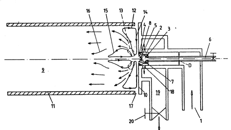
In fig.l an air supply for a burner is indicated by l
where the air has undergone pressure-increasé up to 5 cm of
water column or 500 N/m2. This air is introduced through
~- .
S~)BSTlTlJTE SIHEET
.
,g , J
~ 7-
. . .
axially and tangentially directed slots 2 to a vortex
chambe- 3. This vortex chamber has on its exit side a
tapering down portion 4, which causes the air vortex to be
even stronger before flowing out. The strong vortex leads
to underpressure in the axial area and, therefore, to a
counterfiow, as is schematically indicated with the flow
' lines 5.
By means of a central oll feeding line 6 , oil is
introduced to the conical back surface 7 of the vortex
chamber 3. By means of the counterflow and vorticity of the
air in the vortex chamber 3, oil is forced out along the
cone 7 to reach, via the wall parts between the passages 2,
the surface, which tapers towards the opening 4, where the
vortex air flow 8 ensures that the oil in a thin film moves
along this.surface at a relatively high speed. In the
tapering down portion 4 delamination of the oil film takes
place, which atomizes directly. Due to the vortex break
down, which occurs right after the tapering down 4 ln the
flame room S, an extremely fine atomization takes place.
This flame room has a bac~ su-face lO and a cone wall 11,
drawn as a cylinder.
The flow that leaves the vortex chamber 3, explodes while
forming a very strong turbule~ce, as a result of which
axially an underpressure is c~eated and a counterflow
vortex 12 that flows along the back wall 10 and attaches
itself in ~~stable way to the back wall, partly due to the..
underpressure created by the local flow velocity.
When the flame is ignited, a very concentrated combustion
takes place in the area 13, indicated by a dotted line, the
~ counterflow 14 from the vortex 12, however, provides
cooling of the flame. In the central part in front o~ the
discharge area of the flow from the vortex chamber 3, an
underpressure occurs and as a result a vortex can occur, as
.is indicated by 15. This vortex, too, is stable and
impossible to ~e blown off. Because the main f~ow, as is
indicated at 16, moves again to the axis of the flame room,
SUBSTITIJTE SHFET
, .~ , . .. ~ ...................... ; . ~
. ..-
.
-8-
i. is impossible for gas coming from the exhaust area of
~he burner or even the middle area, to flow bac~ to the
area of the flame.
The slot 17 between the wall 11 and the bac~ surface lo may
provide a secondary-air supply, if so desired. Moreover,
the back surface 10 may be cooled, for instance by water in
case the burner is used for the heating of water in, for
example, a central heating boiler. In stead of secondary
air, exhaust gas or a gaseous product that is to be burnt
may be introduced, in which case the very thorough mixing
by the vortex break down ensures a most efficient
combustion.
i~ As the rotation velocity is only allowed to decrease a
little or not at all, in order to obtain vortex break down
by means of controlling the burner, a control may be
obtained by bringing the combustion air at full speed and
subsequently feeding-back part of this air, as is
schematically indicated by the slots 18 that give access to
a space 19 that has an air exhaust through a control cock
20.
:`
The shown burner has not only a high stability in order to
prevent blowlng off and an exceptionally thorough mixing
of combustion air and fuel and, therefore, a short flame,
it also ensures that a mixture containing oxygen and
nitrogen is..at a high temperature for a short while only.
This is an additional reason why this burner emits few
nitrogen oxides.
The drawn vortex chamber 3 receives its rotating gas
; through the slots 2 formlng a rotation enforcing device.
The axial velocity of the air flowing out, is now inversely
proportional to the quotient of the annular slot zone 2 and
the circular opening in the tapering down portion. It is
very w211 possible that the latter may be larger than the
section of the annular slot, in which case the axial
: velocity is lower when flowing out of the vortex chamber
~ .
SIJBSTIT~ SHEET
than when entering it, which increases even fur,he~ tne
ratio between the rotation velocity and the axial velocity.
Even in the situation in which a rotation enforcing body
causes a vortex with everywhere the same angular velocity
around the axis (solid body rotation) and this vortex is
carried via the tapering down to a more spacious flow tube,
vortex break down occurs again and also an annular vortex.
This causes an exceptionally intensive intermixing of the
gas flow, for instance, when it contains a mixing gas, a
mixing fluid or pulverized particles. In addition, it is
pointed out that the invention is most suitable for the
combustion of pulverized fuel such as coa] particles, but
also of aluminium that can be burnt to aluminium oxide,
which can possibly be of importance in obtaining solar
energy when, by means of solar energy, aluminium oxide can
3e reduced and the aluminium can later be burnt again as a
source of energy.
Fig. 2 ampiifies how a vortex body is created in front of
the e~it opening of the vorte~ chamber, which entirely or
almost entirely prevents the counterflow of air. In the
drawing in fig.3 at point 25, an underpressure is created
by the vortex break down, as a result of which the flow,
indicated by the arrow 26, threatens to develop. The flame
room 27, however, forces the outflowing gases, ~he volume
of which has considerably increased by the combustion, back
to the axls of the room, as is indicated by the arrows 29.
Tnis ensures that the flow 26 remains slight or is even
interrupted, while the flow body 30, due to the
underpressure at 25 and the underpressure created by the
rapid movement of the gases in its immediate vicinity,
remains stabili~ed and is not blown off.
.
Fig 3 shows a schematic cross-section that represents an
advantageous form of the tapering down. It has been found
that when the tapering down is too steep it causes a
certain thrust and that when it is too flat it takes up too
great an axial length and consequently causes too much
SWBSTITIJTE SHEET
. ~ .. .
-10- 21~dt3~1
friction. In the example of fig. 3 the angle made by the
~apering down wlth the axis at the end of the tapering down
is a little smaller than 60 de~rees.
In fig. 4 a further example of embodiment is schematically
represented. Here, the air-supply slot 2 is shown again, by
which axially whirling air enters the space 31, as is
indicated by the arrow 32. This arrow bends inwards,
because from a ring or annular slot 33 radially inflowing
and tangentially whirling gas is introduced, which
preferably has an axial velocity as well. This, however, is
not shown in fig. 4. This air forces the whirling air
coming out of the annular slot 2 inwards, as a result of
which the latter is narrowed and thus causes an expansion
of the vortex.
In the case of an annular slot with a width of 1/8 to 1l4
of the outside diameter D and that has a narrowing with a
diameter of l/2 D (see fig.1,2 and 4),at an axial velocity
in the slot equal to the rotation velocity in situ, a
steadily burning burner was obtained with an outside
diameter of the slot of 17.5 mm, an inside diameter of the
narrowing of 12 mm and a diameter of the burner cone of 90
mm. Such a burner can stand a pressure of introduced
combustion air of 1000 N/m2 without running the risk of
blowing off.
It is remarked that the proportion of the velocities in 2
and 33 and not the absolute value of these velocities is
decisive to obtain vortex break down, by reason of which
the occurrence of this phenomenon can be independent of the
pressure at which combustion air is supplied.
The invention not only provides a compact and most steady
burner, it may also serve to manufacture a burner-spray-
nozzle with a wide adjusting range. Compared to
conventional pressure spray nozzles, such a burner-spray-
nozzle has two advantages:
,
~i .
SUBSTIT~ITE SHEET
2 L ~ 7
25 1) At a low oil through-flow, the atomiz2tion is better
than at a high oil through-flow. As, however, at a high
through-flow the flame is longer and therefore takes up
more room in which mixing can occur, a constant combustion
quality is o~tained at a higher and lowe- oil through-flow.
2) A good air cooling, which prevents the burner from
getting dirty and blocked at high temperatures.
For this reason the invention is suitable as a spray nozzle
for any type of burner that is to mix fuel with combustion
air, for any application with a wide adjusting range.
To elucidate the phenomenon of vortex break down, the
following remarks should be noted.
~! In a rotation-symmetrical two~dimensional continuous flow
it is possible to deduce from the equation of continuity
v. u-O
the existence of a flow function ~ :
U
and
u ~------ . ~ .
- r ~z
If no ~xternal forces are present, and the influence of the
viscosity is neglected, Navier-Stokes becomes:
DU - vu- 1 Vp
with r
C)-V X U
SiUBSTlTllJTE SHEET
,
~ . , . . - . . ... . . .
. . . : .. :. .:-:
. ...... : . . . , -,; :.. . :.. : ,;
, ~, ~ : .. ; ,
. , " . . . ` ~ .
-12- 2 ~
f_- ~he vorticity, this results in:
Th~ ~-component of (1) gives now U~.r = constant = f(~)
;i if we assume the area around the axis to be an area with
'soliv. body' rotation, hence
U~Q.r
and
Q,r2~f(~
~he components of ~ now become:
-u~. d~ u df
~nd
f d- d ( p 1 )
Solving ~p from (1) and (2) gives
~2(p + ~2(1) ~ r2 d ( p+ llU 12) f df
~z2 ~r2 r ~r d~ p 2 d~
so the flow function ~ is given by
~,2~, + ~2~ ~ r 2, d ~ P + - lu 12)-f--
~z2 ~r2 r ~r d~ p 2 d~ ..
with f=nr2.
Now we want to examine what happens if a flow in a cylinder
passes to another cylinder wl~h a larger diameter.
.
Upstream, in the smallest cylinder, we assume in the '
;~ vicinity of the axis a veloci_y UO in the z-direction, so
Uz~ UO ~ ~- 1 UO . r2
:
SUBSTITUTE SHEET
-13- 2~6~ ~ I
, . . ~
hence
f - ~2 . r 2 - 2U
and
_~ df_ (2Q) ~
The Bernoulli surfaces in this flow are cylinders, hence
the pressure, except for a constant term, is given by
p(r)- 2p(UO2+u~ 2) ~ 2pu~2.
Then
P + _IU- i2
p 2
except for a constant, is represented by
2 U02+U~2- 1 Uo2+~22, ~2- 1 U 2+ 2n2 r~p
:~ TAe expression above gives for
r2, d~ P+ 2lu !2)
r d~ p 2 ) Uc
The flow function
~(r,z)-~(r).r+ 2 U~ 2
of a rotating flow in a cylinder is therefore determi~ned by
d~ 2 r dr ( r 2 )~ k- 2UQo
.
.
SUE3STITUT~ SHiEET
..... . ,:i, . ., ., ,. , ~ . .. . ... .. .. .. .
. . . . . .
-14- 2 ~ 3 ~ 7
, .
a Bessel equa~ion of the order 1.
So for the solution, regular on the axis, we find
l~ - A . Jl ( Kr )
~--2 UOr2~A.r.J,(kr~
.~j . uz~ UO+A.k.JO(kr)
u~ U ~-k.
u~ +k.A. Jl(kI).
Upstream, in the smallest cylinder, we assume an axial
velocity UO in an area with vorticity with a diameter 2rO.
Downstream, in the biggest cylinder, we refer to the axial
velocity as U1 within the area with vorticity with diameter
2rl .
For the upstream and downstream flow functions therefore
applies:
~ 2 UOrO2- 2 UOr2~A.r~.Jl(kr,)
: so then
A UO!rO2-rl2)
2r .Ji(krl)
and
u~_l+~ G -l¦. J (k ) .JO(krl) .
If we refer to the axial velocity on the edge of the vortex
upstrea~ as U1, we find a relation between U1, UO, krO'and
krl:
UO (k:r~ 1) J (k~ ) JD(kr~)
` ~i .
$UBSTITIIJTE SHEF~
. - . -. , . ~ . . ~ . ............ . ..
`. . - ,~.~ . . ; ; ., . .. . . .. ` - .. .. ... .
-15- 2 ~
IL k~c is big enough and/or U1/UO small enough ~he above
expression will have no solution. In tha. case ~vort2x
break~ down' will occur.
In~,is. 5 the value of krl/krO is plotted as a function of
krO This shows that initially two solutions are available at
a certain value of krO, subsequently just one in a maximum
and finally none at all. In this last domain vortex break
down will occur, but it should be taken into account that
the flow has always contained smaller vortices which have
not been included in the calculation so that the indicated
_elation can only be regarded as an approximation and
cannot be construed as a limitation to the invention.
_ _
t is easy to observe vortex break down in a burner,
~ecause in that case the combustion takes place in a fairly
small torus shaped zone. This zone is calm and hardly
moves. When oil constitutes the fuel, this zone will have
a blue colour if the oil had already been completely
gasified. As the tem~erature rises, this zone will become a
deeper blue. In case of a less complete gasification,
vellow radiant coal particles may be present in this zone,
~ut experience shows that with a sufficient supply of
~_ oxygen, all unburnt soot particles or hydrocarbons in the
esidual gas are completely burnt.
An importa~ application of the invention is a spray nozzle
or atomizer, where the obtained very fine mist, the very
thoroughly mixed gas mixture or the very homogeneous
suspension of solid particles will not directly be burnt in
the flame room.
. . .
It will be clear that the invention is not limited t~ the
pictured and amplified embodiments. For example, it is
possible that the mixing substance is brought into rotation
prior to coming into contact with the air jet. This is
particularly important in the case of mixing with low-
calorific gas.
SUE~STlTlJTE SlelEET
.
. ,
~ ~ .
2 ~ O ~
. . --16--
f`
The ro_ation enforcing body can have any shape, provided
~hat it superimposes a rotation onto the gas f low. In
addition, it may also contaln moving or rotating parts such
as a blade wheel.
,~''' ,
,.
.
'
SUBSTlTlJTE SHEFT
- . .. . .. . . .