Note: Descriptions are shown in the official language in which they were submitted.
, ~- 210~21
MOLDED WE~THERSTRIP AND MEI~OD
BACKGROUND OF THE INVENTION:
1. Technical Field:
This invention relates generally to a weatherstrip molding, and more particularly
to an injection molded weatherstrip molding for the interface between a vehicle body and
a movable window.
2. Discussion:
Almost all automobiles, and some other vehicles, are equipped with movable
windows adapted to slide from an extended and closed position to a open position which
is retracted within the body of the vehicle. The movable window is usually affixed to a
door of the vehicle. The interface between the vehicle body and the movable window
is generally equipped with a weatherstrip for aesthetically hiding the interface, as well as
providing a squeegee-type blade for cleaning the window as it is extended and retracted.
Belt weatherstrips are generally extruded or roll-formed in a complicated
manufacturing process having many steps. First, a core metal structure is formed having
a longitudinally extending inverted U-shape. In cross-section, each of the two legs of this
core metal structure may be formed with flanges for strength. The core metal structure
is then coated with an extruded layer of synthetic elastomeric material. The coated core
metal extrusion is then cut to length. A sealing strip having a flexible blade for
contacting the window may be formed of a flat longitudinally extending metal strip which
is then coated in an extrusion process with rubber or similar material to form a base
strip. An extruded rubber blade is concurrently formed, extending obliquely beyond the
coated metal base strip. An inner surface of the blade is generally flocked tO provide a
3~,
219~521
low friction coating for reducing friction between the blade and the window. The
resulting sealing strip is then affixed to the U-shaped belt molding. The first leg of the
belt molding and of the base portion of the sealing strip are then notched at
longitudinally spaced locations. A number of clips are then inserted in the notches to
mutually affix the belt molding, sealing strip, and the clips. The clips are also formed for
accepting and gripping a flange edge formed on the door of the vehicle. In addition, a
separate end cap is generally formed independent~y and affixed to one end of the
weatherstrip molding. At the other end of the belt molding, a separate]y formed mirror
patch or window pillar or other detail is affixed to the weatherstrip mo]ding by a joint
llne.
This complicated assembly process involves many separate steps and results in an
expensive and aesthetically ungainly product. In addition, the accumulation of tolerance
values for each individual part and the weatherstrip subassembly may cause significant
variations in dimensions of the weatherstrip. It is therefore desirable to provide a
weatherstrip molding and method for forming it which is simpler, more cost effective, and
involves fewer steps.
SUMMARY OF THE INVENTION:
According to a preferred embodiment of the present invention, a weatherstrip
molding is disclosed for attachment to the body of a vehicle, such as a door, having a
flange edge. The weatherstrip molding is located at a interface between the flange edge
and a movable window which may be raised or lowered to a closed or open position
respectively. The weatherstrip molding consists of a longitudinally extending molding
which is formed by an injection molding process. The molding has in cross-section a first
21065~i
and second leg joined together by a web to define a U-shape and a first channel between
the first and second legs. At least one retainer clip may be integrally forrned with the
molding to define a second channel which is smaller than the first channel for accepting
the flange edge. The clip is preferably integrally molded at the same time as the
remainder of the molding is formed. Alternatively, the clip may be pre-formed and
inserted into the mold before the injection molding process, during which the molding
is then molded around the clip, whereby the clip becomes integral with the remainder of
the molding.
These and other various advantages and features of the present invention will
become apparent from the following description and claims7 in conjunction with the
appended drawings:
BRIEF DESCRIPTION OF THE DRAWINGS:
Figure 1 is a partial side elevation of an automobile;
Figure 2 is a partial perspective view of a weatherstrip molding according to the
present invention, and a cutaway view of an attached sealing strip;
Figure 3 is a cross-sectional view of a weatherstrip molding according to the
present invention affixed to a flange edge of an automobile door taken along line 3-3 in
Figures 1 and 2;
Figure 4 is a cross-sectional view similar to that in Figure 3 taken along line 4-4
in Figures 1 and 2;
Figure 5 is a cross-sectional view of a weatherstrip molding according to the
present invention taken along line S-5 in Figure 4;
2106521
Figure 6 is a partial perspective view of an altemative embodiment of the present
invention;
Figure 7 is a cross-sectional view of the weatherstrip molding of Figure 6 taken
along line 7-7;
Figure 8 is a partial perspective view of a second alternative embodiment of the
present invention;
Figure 9 is a cross-sectional view of the weatherstrip molding of Figure 8 taken
along line 9-9; and
Figure 10 is a partial perspective view of a third alternative embodiment of the
present invention.
DETAILED DESCRIPTIO~ OF THE PREFERRED EMBODIMENTS:
The following description of the preferred embodiments is merely exemplary in
nature, and is in no way intended to limit the invention, or its application or uses.
With reference to the drawings, Figure 1 shows a partial side elevation of an
automobile 10 having a door 12, a movable window 14, a mirror patch 16, and a
weatherstrip 18 attached to door 12 at an interface between window 14 and door 12.
Weatherstrip 18 extends longitudinally along the lower edge of window 14 and operates
to aesthetically conceal the interface between door 12 and window 14. Window 14 may
be slidingly moved between an extended and closed position, as is shown in Figure l, and
a retracted and open position.
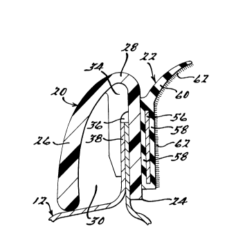
Weatherstrip 18 of the present invention is shown in Figures 2 through 5, and
consists of a weatherstrip molding 20, as well as an attached sealing strip 22. The novel
weatherstrip molding 20 of the present invention extends longitudinally and has, in cross-
$21~521
section, a first and second leg 24 and 26 joined together by a web 28 defining an invertedU-shape and a first channel 30 between first leg 24 and second leg 26.
In the embodiment shown in Figures 3 and 4, molding 20 is formed with at least
one notch 32, and at least one retainer clip 34 preferably formed as a tab located
longitudinally adjacent or opposite to notch 32 extending downwards from web 28
substantially parallel to first leg 24. Retainer clip 34 defines a second channel 36
between the longitudinally spaced inner surfaces of clip 34 and first leg 24 for accepting
a flange edge 38 of door 12. Second channel 36 is of course smaller than first channel
30, because clip 34 extends between first and second legs 24 and 26.
Clip 34 is preferably formed with a ramped projection 46 having an angled lead-in
surface 50 for facilitating installation of molding 20 onto flange edge 38 and a catch
surface 52 for inhibiting subsequent removal of molding 20 by engaging a thrust bearing
surface 54 created by an aperture 48 formed in flange edge 38. Clip 34 may also be
formed with an interference fit with first leg 24, such that a portion of clip 34 extends
into notch 32 for an enhanced and more secure fit onto flange edge 38.
Weatherstrip molding 20 may be integrally formed with a laterally and transversely
extending end wall 40 as shown in Figure 2, rather than a separately formed end cap, for
enclosing the weatherstrip assembly at the opening end of front door 12. At the opposite
end of molding 20, an end detail may be integrally formed, such as for example a mirror
patch 16, as shown in Figure 1. Mirror patch 16 is a triangular shaped portion for
cooperating with a rear-view mirror located at the front of front window 14. In addition,
the weatherstrip molding of the present invention may be formed as a rear weatherstrip
molding 19 as shown in Figure 10 for use on a rear door 13. Rear rnolding 19 may be
formed with a more complicated end detail, such as a rear corner filler 42, which
21~6~21
may also be formed with fastening means 44 for fastening rear corner filler 42 onlo the
body of automobile 10. Rear molding 19 may also be formed in a curved shape to follow
the contours of doors 12 and 13.
Weatherstrip 18 includes sealing strip 22 which is affixed to first leg 24 of
weatherstrip molding 20. Sealing strip 22 has a longitudinally extending metal base
plate 56 which is surrounded by an extruded coating 58 of rubber or similar material, as
well as a blade portion 60 extending obliquely upward and inward for contacting
window 14. An inner surface of sealing strip 22 is nocked by a method known in the art
with flocking material 62 which provides a low friction coating for reducing friction
between blade 60 and window 14. Flocking material 62 may be placed only on the inner
surface of blade portion 60, as opposed to the entire inner surface of sealing strip 22.
Sealing strip 22 may be affixed to molding 20 by a variety of methods generally known
in the art, such as with an adhesive. Sealing strip 22, especially blade portion 60,
provides a seal between the interior of door 12 and the external environment to prevent
entry of contaminants and other debris into the interior of door 12. Blade portion 60
also cleans the outer surface of window 14 as it is extended and retracted. Sealing strip
22 may also be formed with apertures for insertion of a tool for opening clip 34 and
easily removing strip 22 from flange edge 38.
Weatherstrip molding 20 is formed by an injection molding process of a plastic
material which is preferably a thermoplastic or thermoset material, such as for example,
polypropylene, an acetal, nylon or a nylon blend. An elongated mold is formed having
an upper and lower shell (not shown) which have interior surfaces shaped to define first
and second legs 24 and 26, web 28, and any desired end details such as end wall 40,
mirror patch 16 or rear corner filler 42. In the embodiment shown in Figures 3 and 4,
2106~21
the lower shell of the mold (not shown) also defines the interior shape of retainer clip 34,
and a side detail insert mo]d is used in conjunction with the upper and lower shells to
form notch 32 and the outer facing surfaces of clip 34, including second channel 36 and
projection 46. The thermoplastic or thermoset material is allowed to cure and harden
or solidify within the mold, and is then removed from the mold to form a one-piece
molding 20. Sealing strip 22 may be concurrently formed as is known in the art, and then
affixed to first leg 24 of molding 20.
An alternative embodiment of the present invention is shown in Figures 6
and 7, in which first leg 124 of molding 120 is formed with a longitudinally extending
ridge 164 which is formed in the mold when molding 120 is formed. Base 156 and its
surrounding coating 158 are also formed with a similar longitudinally extending ridge 166,
as shown in Figures 6 and 7. Ridge 166 allows the use of a separate mechanical
fastener 168 for fastening sealing strip 122 to molding 120. Fastening means 168 may be
formed as a staple or a stitch, and may be used in conjunction with an adhesive, and
results in sealing strip 122 being more firmly secured to molding 120. Separate
mechanical fasteners of this type have generally not been used in the art because of the
possibility of scratching the glass of window 14 when it is extended or retracted.
However, flocking 162 on ridge 166 prevents window 14 from contacting fastener 168,
thus reducing the likelihood of scratching window 14.
A second alternative embodiment of the present invention is shown in
Figures 8 and 9, in which retainer clip 270 are pre-formed and are then inserted into the
mold before the thermoplastic or thermoset material is injected into the mold. Retainer
clip 270 thus becomes integral with molding 220 when the thermop]astic or thermoset
material cures around retainer clip 270. Retainer clip 270 may be formed having a
2106521
variety of cross-sections, including one similar to retainer clip 34, or may be formed as
shown in Figure 9. Retainer clip 270 is formed with a base portion 272 and a leg 276
connected to base 272 by a web 274. Leg 276, and possibly base 272, may be formed
with a lead-in surface 278 for facilitating insertion of molding 220 onto flange edge 38 of
door 12.
Finally, in a third alternative embodiment, retainer clips may be pre-formed
independently and then clipped onto molding 20 after it is removed from the mold.
These retainer clips are also formed with a second channel for accepting and gripping
flange edge 38 of door 12.
It should be understood that an unlimited number of configurations of the present
invention can be realized. The foregoing discussion discloses and describes merely
exemplary embodiments of the present invention. One skilled in the art will readily
recognize from the discussion and from the accompanying drawings and claims that
various changes and modifications can be made without departing from the spirit and
scope of the invention, as defined in the following claims.