Note: Descriptions are shown in the official language in which they were submitted.
21 06~23
PATENT
ON 48203
ELECTRONIC TEMPERATURE CONTROLLER
FOR WATER HEATERS
BACKGROUND OF THE INVENTION
This invention relates generally to control of liquid heaters such as water
heaters. More particularly, this invention pertains to devices and methods for sensing
and me~ ring operating values of flow-through water heaters, as well as using such
values to actuate certain control aspects of the water heaters.
Safe operation of water heaters and the like requires that overheating be
10 avoided. In water heaters in which energy is introduced through electrical elements,
the water level in the vessel may perchance be below the level of an element.
Without contact with the liquid "heat sink", the element may heat to e.g. 1000 degrees
F in less than a minute. The element may melt and fall into the vessel bottom,
(l~m~ging the coating on a tank or the tank itself. When the vessel wall is constructed
15 of a non-metallic material, heat generated by the overheated element may permanently
damage the vessel wall. It may be necessary to shut off the power supply to the
2lass23
2 PATENT
ON 48203
element in a fraction of a minute, for example, in order to avoid damage to the
element or the vessel.
In the prior art, a thermostat controls the heating elements based on the
measured water temperature. In the "dry-fire" condition, the water temperature being
5 sensed at the thermostat may not rise beyond the parameters seen under a normal
heating condition, before damage will occur. Thus, reliance cannot be placed on the
normal thermostatic control to detect and react to a "dry-fire" state.
The use of thermal fuses in the element port requires that a new fuse be
installed upon each thermal overload incident. More importantly, the critical element
10 temperature may sometimes be reached before the fuse overload telllpe,dlur~ is
reached; the fuse may not respond in time to prevent damage to the elements or water
heater vessel.
For gas-fired water heaters, other problems exist. In a modern water heater
having a non-metallic vessel, the water is pumped from the vessel through an exterior
15 heating circuit. The circuit includes a heat exchanger, typically a coil, where heat is
transferred from the flame and hot combustion gases to the circulating water. A
temperature sensor is normally positioned in the heating circuit to measure the water
temperature and control the firing cycle.
If the water level in the vessel should drop to below the inlet pipe to the
20 exterior heating circuit, the coil will become empty and the flame and hot combustion
gases will overheat the empty coil. The danger of (l~m~ging the heat exchanger coil
exists.
21G6323
3 PATENT
ON 48203
Other operating disfunctions may also occur. For example, a thermal sensor
may be accidently left disconnected from the vessel or the controller. In such cases,
the controller will not sense a temper~ture change, even though the water is being
heated. The burner or electrical element will continue to provide thermal energy to
S the unit even though the m~ximllm planned temperature is exceeded. An unsafe
overheat condition may result which damages heater components.
Furthermore, while all water heaters have a safety valve actuated by excess
pressure/temperature, this valve will not respond to a dry-fire condition, where there
may be no water to expand and overpressuri_e the vessel, and where any existing
water is being heated at a sub-normal rate.
In prior art water heaters, there has been no satisfactory system for minimi7ingpower or fuel usage while simultaneously ensuring adequate hot water supply at t he
desired temperature and in addition, ensuring safe operation.
The industry needs a~paldlus and procedures for sensing and calc~ ting actual
operating conditions, for detecting unsafe operations reslllting from low water levels
or disconnected sensors, for taking action to alleviate the unsafe operations, and for
determining energy usage and projected heating times.
BRIEF SIJMMARY OF THE INVENTION
The invention is a method and appaldtus of temperature control for a liquid
heating apparatus such as a domestic or commercial water heater, where the heat is
supplied by an electrical element or by the combustion of a fuel such as a fuel gas or
210682~
4 PATENT
ON 48203
oil. Specific operations of the heater are initi:~ted if and when the measured rate of
e~l~peldlulc change attains predetermined settings.
Whereas prior water heaters and the like have used a simple upper temperature
limiting value for ~hutting off the thermal energy source in the event of a malfunction,
5 this invention uses a different function of the temperature measurement. The time rate
of change of the measured temperature is continuously, semi-continuously or
sequentially calculated by the control unit, and applvpriate corrective actions initi~ted
if the rate e.g. degrees per minute, is not within the normal operating limits. The
particular action taken depends upon the measured value of the rate. Specific
10 abnormal events in the heater operation produce identifiable rates which are peculiar
to the particular malfunction.
Thus, a normal temperature control scheme using temperature control limits
about a preset desired value may be combined with the safety system of the present
invention for detecting abnormal operation and ~hlltting off the input energy, whether
15 electrical power or fuel. Of course, a pressure/telllpeldlure relief valve is also used
as a backup safety measure and to meet industry standards.
In the invention of the present method and apparatus, the rate of temperature
change, positive or negative, is electronically determined or calculated over small time
increments. The range of "normal" rates of tc-~pel~turc change may be calculated
20 from the known heater configuration, or may be determined from actual use. With
the heat source operating at maximum output in a full liquid vessel, the time rate of
increase in te~l~pe,~lurc is the m~ximum to be expected under normal operating
conditions. A severe low water condition, i.e. "dry-fire", results in a sensed rate of
210S829
PATENT
ON 48203
temperature increase which is typically 5-25 times greater than the maximum "normal"
rate.
Likewise, a malfunction in the burner or heating element, disconnection of the
lelllpt;ldlure sensor, or problems associated with the flue, etc. may result in a
5 temperature change rate well below the normal rate. In either an above-normal or
below-normal rate, the controller may use the calculated rate to sense and determine
the aberration and apply a programmed action which prevents hazardous operation and
energy wastage. In the event of burnout of an element of an electrical water heater,
the controller may be programmed to switch to another element until maintenance
10 service can be provided. The controller may also provide warnings and instructions
for correction of malfunctions.
Other details and advantages of the invention will be readily understood by a
reading of the following description in conjunction with the accompanying figures of
the drawings wherein like reference numerals have been applied to designate like
15 elements throughout the several views.
BRIEF DESCRIPTION OF THE DRAWINGS
In the Figures,
FIG. 1 is a partially cut-away side elevation of an electric water heater having
20 the control system of the invention;
FIG. 2 is a generalized wiring schematic of an embodiment of the control
appaldl~ls of the invention for an electric water heater;
2106~29
6 PATENT
ON 48203
FIG. 3 is a graphical representation of the relationship between water level andsensed telllpe-d~ul~ in the vessel of an electric water heater of the invention;FIG. 4 is a flow chart showing exemplary logic steps of the controller of the
invention as typified in FIG. 2;
S FIG. S is a partially cut-away side elevation of a gas-fired water heater to
which the invention is applied;
FIG. 6 is a front view of an embodiment of the sensor mounted on a
exemplary port in accordance with the invention; and
FIG. 7 is a lateral sectional view of an embodiment of sensor and port in
accordance with the invention.
DESCRIPTION OF lll~; PREFERRED EMBODIMENTS
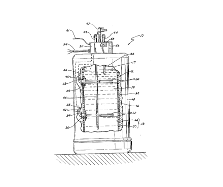
With reference to the drawings, and particularly to FIG. 1, an electric water
heater 10 is shown with the general control elements of the invention. The waterheater 10 comprises a vessel generally design~ted by the numeral 12 for holding and
heating water 14. The water 14 is shown as having a variable upper level 15. Thewater heater 10 is shown as including insulation 16 overcovering a major portion of
the vessel 12, and an external shell or jacket 18. The heater 10 also includes heating
means which comprises upper and lower electric heating elements 20 and 22 mounted
in ports 24, 26 passing through the vessel wall 28. A controller unit 30 receives
readings from lt;lllpe dlure sensors 32 and 34 through conduits generally de~ign~ted
as 36 and 38, respectively and controls the introduction of electrical power from
supply conduit 54 through conductor sets 40, 42 to the heating elements 20 and 22.
210~82~
7 PATENT
ON 48203
The heater 10 also includes water inlet pipe 44, outlet pipe 46, and
pressure/temperature relief valve 47.
While the invention is useful with metallic or non-metallic vessels, it is
illustrated in a particularly advantageous application with a non-metallic vessel 12.
S The vessel wall 28 is illustrated as being a l~"in~e formed of an inner layer or liner
48 and an outer layer 50. The cylindrical portion 52 of the outer layer 50 is typically
oriented vertically and may be formed of fibers or other materials in a thermoset resin
substrate for providing the necessary strength, rigidity and structural integrity at the
elevated operating conditions. The inner layer 48 is made of a material which isresistant to deterioration and leakage at the operating environment within the vessel
12. However, such materials typically deform or melt at a lower temperature thansteel or glass-lined steel, and therefore must be protected from excess temperatures
resulting from "dry-firing" i.e. operating with an electric heating element
unsubmerged in the water.
The elements 20 and 22 may be individually controlled in sequence to achieve
the desired supply of hot water with enhanced energy conservation. When the
required water supply is relatively low, the heater 10 may be reduced in size and have
only a single heating element. More than two elements may be used if desired,
operated in sequence.
Small single element heaters have the element mounted in the lower portion of
the tank for heating the entire vessel contents in a relatively short period of time.
Larger vessels having a greater length:diameter ratio may require two or more
elements to enable some heated water to be available in a reasonable period of time
21068~
8 PATENT
ON 48203
rather than wait for the entire vessel contents to be heated to the desired temperature.
Multi-element heaters are operated so that the elements actuate sequentially to reduce
the maximum power draw and minimi7e overall power consumption.
The control unit 30 is shown with a control panel 56 for ch~nging control
S settings, acces~ing control memory, etc. Measured and computed values of control
factors, status information, instructions and various warnings may be accessed or
viewed on a display 58 for ease of control.
In the present invention, the controller includes a microcomputer. A control
program is written into the ROM (read only memory) or EPROM (erasable
10 programmable read only memory) to include setpoints; variable data such as sensed
"water" temperatures at one or more locations and status of the heating elements may
be stored in the RAM (random access memory). The controller functions and set
points may be controlled from the control unit or panel 30 at the water heater 10. If
desired, the apl~al~lus may be configured so that the collected data and functions
lS calculated thelerlulll may be electronically transferred via remote cable 61 for access,
viewing and control at a remote station, not shown in FIG. 1. Thus, for example,
setpoints may be preset and various other specific operations controlled from a remote
console.
The controller may be programmed to include various modes of operation such
20 as calibration. Thus, in a "calibration" mode, the controller acts as the means for
standar~ g and calibrating the water heater functions to counteract any variations
in the equipment. For example, slight dirrel~nces in sensor calibration may be
accounted for in the co",pulel program to achieve uniformly accurate heater operation.
2106~29
9 PATENT
ON 48203
The lell-peldlul~ sensors useful in this invention may be of any fast-acting type
with an electronic or electrical output. Thermisters, RTL~s or other resistance output
sensors are typically used because of their simplicity, reliability and cost.
The sensors 32, 34 are typically mounted on heat conductive ports 24, 26 at
5 or above a critical level in the vessel 12. This critical level may be the level of a
heating element of an electric water heater. Activation of an element with a water
level below the critical level results in a condition of "dry fire".
In a fuel fired water heater having a sep~le heating circuit external of the
vessel, the critical level may be the level of the entrance to the heating circuit within
10 the vessel. Loss of liquid level to below that point will result in a dry recirculation
pipe, also denoted herein as "dry fire".
During normal heater operation, the port is in contact with liquid water 14 and
rapidly conducts heat to the sensor. The sensor's output reflects the water
temperature.
Dry fire in an electrical water heater occurs when the heating element is
activated when not immersed in water. In this state, the sensor port, being at the
same level, is also subst~nti~lly or completely not in contact with the water, and
receives heat by direct conduction and radiation from the hot heating element.
Without the liquid heat sink to absorb the thermal energy, the increased heat transfer
20 to the port results in a rapidly rising port temperature which is sensed by the sensor.
This temperature rise rate is subst~nti~lly higher than that during normal operation,
and is the means by which a "dry fire" condition is detected.
2106~29
PATENT
ON 48203
In a fuel fired water heater with a separate heating circuit, the sensor may be
mounted on the port by which heated water enters the vessel, or on its own port. The
water heater should always be full of water and pressurized to the house system
pressure. During normal heating operation, the sensor senses a normal temperature
5 rise rate of the water absorbing heat from the burner. Should the water level be so
low as to produce a "dry fire" condition, the sensed temperature will not rise at a rate
in the normal range but will rise more slowly, if at all. This low rate of temperature
rise is detected by the controller.
When the controller calculates a temperature rate of change which equals a
10 preset value representing "dry fire", the controller shuts off the heating energy to
prevent damage to the water heater components. For an electric water heater, "dry
fire" is detected when the rate of temperature change meets or exceeds the preset
value. For a fuel fired water heater with a separate heating circuit, "dry fire" is
detected when the rate of temperdture change is equal to or less than a preset value
15 representative of a "dry fire" condition.
Port constructions useful in the invention are described infra and shown in
FIGS. 6 and 7.
FIG. 2 shows a simplified electrical diagram for an exemplary two-element
electric heater of the invention. The controller unit is pictured as including a power
20 board 86 and a display board 88. An upper heating element 20 is mounted in upper
port 24, and a lower heating element 22 is mounted in lower port 26. Element 20 has
terminals 64, 66 which are shown connected to a 240 volt power supply 68 by wires
70, 72 through switch 74. Likewise, element 22 has te~ als 76, 78 which are
2106829
11 PATENT
ON 48203
connected to the power supply 68 by wires 80, 82 through switch 84. The power
supply 68 is introduced through circuit breaker 90. The two ports are grounded by
ground wires 60 and 62.
Attached to the upper and lower ports 24, 26 are te---peldlul~ sensors 92, 94
S for sensing the water temperatures at those levels and for activating/deactivating the
heating elements 20, 22 to m~int~in preset temperatures. These sensors also provide
temperature signals for calcul~ting the timed rate of change in temperature, and for
calc~ ting values of other operating parameters, if desired. Each sensor is connected
to the controller unit by 2-wire leads 96, 98, respectively. A safety sensor 100 is
10 attached to the upper port 24 and is connected via a 2-wire lead 102 to the controller
unit. This sensor 100 is a backup upper limit temperature sensor for shl-tting the
heater down if a high temperature is detected.
The display board is shown with a display 58 for viewing values of control and
~eldlih~g functions. If desired, alarms, instructions and other information may be
15 displayed here in accordance with the programmed controller. A panel 104 is shown
with keys for accessing the memory of the controller and for presetting and viewing
control variables. The various electronic conduits connecting the display board 88 and
power board 86 are represented by line 106.
If desired, display and control functions may be routed to a distant
20 monitor/controller via remote cable 61.
FIG. 3 illustrates the principles of the control process, as applied to a water
heater with electrical heating elements. The actual element temperature TR and sensed
"water" temperature TM~ together with the rate of change R in sensed temperature, are
21Q6g2~
12 PATENT
ON 48203
plotted as a function of time. The figure illustrates what occurs when a heater is
started without first filling the vessel with water. Such may occur upon an initial
start-up or following Illainlenallce, for example. A dry-fire condition may havecatastrophic effects upon the heater if not checked in a short time.
In this graph, tA represents the time at which the elements are electrically
activated for heating the water.
From the figure, one can see that the element temperature quickly attains about
1000 degrees F. at time TD~ typically in less than one minute. The measured "water"
telll1)e1~lU1~1;; TM is shown as rising much more slowly, i.e. at a rate RB. Rate RB is
however much higher than the rate RNORMAL of temperature change during normal
operation with water present.
In this invention, the controller may be preset to shut off the power to the
element if the rate of temperature change reaches Rc, a value less than the maximum
measured rate RB. The time for this to occur is very short, i.e. TC ~ TA. Thus the
element is deactivated long before it approaches a deleterious temperature. The
possibility of damage to the heating elements and vessel is avoided.
It should be noted that the deactivation of this method occurs before the sensed"water" temperature reaches a high temperature cutoff at e.g. 180 degrees F. Use of
such a cutoff based on temperature rather than a rate of temperature change is not as
20 effective in preventing damage to the element, vessel or other heater components.
FIG. 4 shows an exemplary set of mathematical steps which result in values
for various operating parameters useful in assessing and controlling the heater
2106829
13 PATENT
ON 48203
operation. The steps are shown for an electrical heater, and are to be slightly modified
when used with a fuel fired heater.
The sensed te-llpel~ule T is read at time tn to give temperature value Tn. The
value is stored. A previously sensed temperature Tn y sensed at time tn_X is subtracted
S from Tn to yield a temperature change dT over time period dt. These values may be
stored for future reference.
The ratio of dT to dt is calculated to produce a rate of change in temperature
Rn when the heating element is activated For an exemplary electrical water heater, Rn may be on the
order of 1-2 degrees F per minute during normal heating operations. Various
opeldling parameters of the water heater may be delelll~ ed from abnormal calculated
values of Rn:
(a) as long as the water level is above the sensor, the volume of water in the
vessel may be determined as an inverse function of Rn;
(b) a value of Rn which is zero or near-zero indicates that the sensor is not
operating, possibly because it is notplopelly installed. Alternatively, the
heater is not operating, despite being electrically activated;
(c) a value of Rn which is below the normal operating range may result from
a high water usage rate or a malfunctioning element;
(d) a value of Rn which is higher than the normal range indicates a low water
level reslllting in a "dry fire" condition; typically the "dry fire" value of Rn is
2-10 times the normal opel~ling value of Rn; and
(e) the time required to heat the water from the present temperature to the
preset operating temperature may be calculated by dividing the temperature
2106~2~
14 PATENT
ON 48203
difference by the heating rate R,. If the rate Rl, varies with actual water
temperature, correction factors may be included in the co~ u~lion program
to provide the desired accuracy.
Specific actions may be programmed into the controller to shut off the heating
S element(s) when an abnormal operation is in~ t~d. In addition, messages indicating
the problem and recommended action may be recalled from memory to be displayed
on the monitor.
It should be recognized that the mathematical functions may take alternate
forms, yet provide the same information. The foregoing discussion is exemplary in
10 nature and provides the colllpulalional steps in their simplest form.
The major components of a gas-fired water heater 110 having the control
method of the invention are shown schematically in FIG. 5. The heater is shown with
a vessel assembly 112 and a separate heating module 114. A non-metallic interior
vessel 116 contains the heated water 122, and is covered with insulation 118 and an
15 exterior jacket 120.
Water 122 is heated by combustion gases 124 from burner 126. Water 122 to
be heated is drawn from the vessel 116 through vessel outlet pipe 128 into heat
exchanger coils 130 which lie in the stream of hot combustion gases 124. Heated
water passes from the coils 130 to pump 132, which pumps the water through vessel
20 inlet pipe 134 into the vessel 116. Fuel gas is passed through gas supply line 136 to
burner 126, and is controlled with a valve 138 by controller subunit 140. The fuel
may be ignited by any a~a~alus used in the industry.
~lQ6829
15 PATENT
ON 48203
Heated water is drawn from the vessel 116 through hot water line 142. Supply
water is introduced to the water heater vessel 116 through an inlet 144 to replace
water withdrawn.
The vessel inlet pipe 134 is shown mounted in a heat conductive port 146. A
S telllpel~lure sensor 148 is mounted on an exterior portion of the port 146 to measure
the temperature of water 122 adjacent the interior surface of the port. An electrical
signal is tr~n~milte~ from sensor 148 through 2-wire leads 150 to the controller unit
158, which then controls the activation of the gas valve 138 and burner 126 through
controller sub-unit 140 to m~int~in the desired preset water temperature. The sub-unit
140 may include a standard ignition control unit which is well known in the art. A
second sensor 152 is shown attached to the port 146. This sensor may be used fortimed temperature measurements used in calculating various water heater functions
based on the time rate of change in temperature. Sensor 152 is shown with 2-wireleads 154 for tr~n~mitting the temperature measurements to the controller unit 158.
Alternatively, all of the measured temperature values could be obtained from
a single sensor, or each function could be computed using its own .emperature sensor.
As with the electric water heater, several possible functions may be computed
by the controller, based on a calculated time rate of temperature change. These
include:
(a) the volume of water in the water heater, and/or water level 156 in the
vessel 116,
(b) the elapsed time to heat the water in the vessel,
(c) a disconnected or non-operative sensor, and
16 2 1 ~ 6 8 2 9 PA1~3NT
ON 48203
(d) a low water level resultin~ in a "dry fire" condition.
In contrast to the values indicating such a condition in the electrical water
heater, the indicative rate value is zero or a very low value, because the heater is
remote from the sensor. In such a "dry fire" condition, a lack of recirc~ tin~ water
S results in essc~ lly no heat transfer to the vessel contents comprising air and water
vapor.
The controller shown comprises subunit 140 and controller unit 158 having a
display 160 and manipulable controls 162 for aGcessin~ the memory and control
functions. Preferably, all co~ ul~ions and data h~n-llin~ are performed in controller
10 unit 158, from which signals are tr~n.~mitted to subunit 140 to actuate the fuel valve
138. This permits standard off-the-shelf items to be used in subunit 140.
,~ltt .rn~tively, the various c ~ u~ion and memory functions may be
distributed in any way between the subunit 140 and controller unit 158; these two
units are conl-~t~l by electricaVelectronic conduits ~ sel-led by line 164.
The ports provide a large surface area for water
contact with a path for high thermal conduction rates to
a sensor. In addition, they provide for direct
conduction of heat from a dry heating element, as well as
for heating of the port by radiation from the dry
element.
One of these port 170 configurations is shown in
FIGS. 6 and 7, with a bayonet mounted electrical heating
element 172 ready to be installed therein. The port is
shown with an annular outer flange 174 which provides a
continuous metal path to
2106g~3
17 PATENT
ON 48203
the interior of the vessel. The interior portion of the flange 174 has a surface 176
normally in contact with water. This surface 176 also is close to the heating element
172 so that during a "dry fire" event, heat is transferred to the port 170 by radiation
as well as by conduction. A t~lllpeldlult;; sensor 178 is attached to a hole 182 in the
5 flange 174 for sensing the te~lpeld~ure of the port. The sensor 178 is connected to
a control unit, not shown, by 2-wire conduit 180.
The heating element assembly 184 is sealed in port 170 by o-ring 186, and
held in place by lock ring 188 with handles 190. Terminals 192 of the heating
element 172 are connected to a power source through the controller.
The advantages of this system include:
1. A rapid shutdown in the event of a "dry fire" episode.
2. Various parameters important to the efficient operation of the heater may be
continuously or semicontinuously determined.
3. The system may be adapted for either electrical and fuel fired heaters, with minim~l
configurational changes.
4. The control system uses minim~l hardware space.
5. Status of the water heater may be o~tained at any time, together with instructions
in the event of a malfunction.
6. The ap~ tus is inexpensive to manufacture, and easy to install.
It is anticipated that various changes and modifications may be made in the
construction, arrangement and operation of the heater control system disclosed herein
without departing from the spirit and scope of the invention as defined in the following
clalms.