Note: Descriptions are shown in the official language in which they were submitted.
'- ~ 92/16246 21 ~ PCI/US91/0~144
APPARATUS~ METHOD FOR EYE I~RIGATION AND ASPIRATION
BACgGRO~ND OF q~IE INV~TION
The present invention relates to material removal
devices, and, more particularly, to an irrigation and aspira-
tion instrument having a selectively hooked or stralght portion
at the operative end thereof for irrigating and aspirating
material from relatively inaccessible places. Although by no
means limited thereto, the present apparatus is of particular
advantage when employed in surgical procedures for removing
material from the capsular bag of the eye.
Conventional vibratory instruments for the removal of
material from the eye have used a handpiece having a straight
operative tip at the end thereof. U.S. Patent No. 3,589,363,
which is incorporated herein by reference, involves an instru-
ment having a handpiece which has an elongated tip at one end.
The elongated tip is inserted through an incision made in the
cornea. The instrument is capable of vibratlng the operative
tip at ultrasonic fxequencies of variable amplitude and dura-
tion to break apart particles of the material, such as acataracted lens, to be removed.
A source of fluid and a source of fluid suction are
provided at the operative end of the instrument, respectively,
to dispense and withdraw fluid to and from the area in proxim-
ity of the material to be removed.
Fig. 1 illustrates the conventional solution toremoving material from the eye. The opaque lens or cataract to
SUBSTITUTE SHEET
W092/16246 ~ ) PCT/US91/O~l~
be removed is designated as 10 and is encased in a membrane or
capsular bag 12, including a front portion closest to the
cornea, known as the anterior capsule 12a, and rear portion,
known as the posterior capsule 12b.
Typically, a small incision 1~ is made in the cornea
16 as far as possible from the center of the pupil area. The
central portion of the anterior wall is opened up for access
and instrument such as that descrlbed ln Patent 3,589,363 is
used to fragment the cataracted lens and to aspirate the
fragments from the accéssible reglons of the capsular bag such
instrument has an elongated straight tip 20, seen in Fig. 1,
capable of supporting ultrasonic vibrations. In this arrange-
ment, particularly if the anterlor wall openlng i5 relatlvely
small, only the central region of the interior of the capsular
bag 12 is readily accessible to the tip, since the amount of
manipulation by manually moving the handpiece 22 within the
capsular bag 12 is relatively limited by the straight tip being
confined at two locations along its length, namely, by the
small incision in the cornea and also by the remaining periph-
eral portions of the anterior wall of the capsule.
For example, the handpiece 22 can be moved at anglesA" ~, A3 and A4 to enable the elongated straight tip 20 to
reach different portions in the central region of the capsule.
However, the capsule portions at the periphery of the capsular
bag are not readily accessible to the elongated straight tip 20
because the size of the incision and the remaining anterior
wall of the capsule 12 restrict the movement of the elongated
straight tip 20. Therefore, the elongated tip 20 can not
easily be moved to angles whlch would enable it to reach the
interior peripheral portion of the capsule 12. Thus, it is
very difficult for the surgeon using the conventional instru-
ment to manipulate it so as to remove material, e.g. fra~ments
of the cataracted lens, which is located at the inner peripher-
al regions of the anterior capsule 12.
SUBSTITUTE SHEET
h ~
~'~92/16246 ~CT/US91/08144
SUMMARY OF T~E INVENTION
This invention is directed to a material removal
apparatus in which problems with the prior art devices are
eliminated. It is, therefore, a general gbject of the inven-
tion to provide an apparatus capable of removing materlal fromtissue of an enclosed area. More specifically, it is an object
of the present invention to provide a working instrument to
aspirate and irrigate all regions of the posterior capsule of
the eye even though the peripheral portions of the anterior
wall of the capsule rémain intact.
Another object of the present invention is to provide
a surgical instrument having an operative tip capable of being
selectively transformed from a straight tip to a hooked tip,
whereby material to be removed, which is located in the periph
eral interior region of the capsule, can be withdrawn.
In accordance with this invention, an irrigation and
aspiration surgical instrument i9 provided with an elongated
tube having a resiliently deformable tip portion. The tip
portion has a hooked shape in a relaxed condition. A sleeve
means, as for example a tubular sleeve, is slidably movable
onto the tip portion, to straighten the hooked tip portion into
a straightened condition, and off the tip portion to allow the
latter to again assume its relaxed hooked configuration. When
the tip is in a straightened condition the tube may be readily
inserted into the incision in the cornea and into the capsular
bag. The tip, in straightened condition, may be manipulated by
moving the handpiece to reach regions of the capsular bag
across from the region at which the tip entered the eye. The
tip resiliently returns to its relaxed hooked shape upon moving
the tubular sleeve off the straightened tip end portion and
back along the tube. With the tip in a hooked shape, it may
extend to and be used in the inner peripheral regions of the
capsular bag. Thus, those regions may also be aspirated to
remove tissue and fluid there from.
SUBSTITUTE SHEET
WO92/1624~ PCT/US91/08144 ~~
Other objects and advantageo~ls features of this
invention will be apparent from the following description of
the preferred embodiment with reference to the accompanying
drawings.
BRI~F DESCRIPTION OF ~HE DRAWI~GS
Fig. l is a pictorial representation of a convention-
al instrument showing the use in cataract removal.
Fig. 2 is a partly schematic, partly sectional, view
of the instrument according to the present invention showing
the tip in relaxed, hooked condition.
Fig. 3 is a partly schematic, partly sectlonal, view
of the instrument according to the present invention showing
the tip in straightened condition.
Fig. 4 is a pictorial representation of an instrument
according to the present invention showing the use in removal
of material from inner peripheral regions of the capsular bag.
DETAI~ED DESCRIPTION OF T~E DRAWINGS
In the ensuing detailed description, the invention
will be described in terms of its use as a surgical instrument,
particularly as applied to cataract removal. However, it will
be understood that the principles of the invention are not so
limited, and the apparatus described may be capable of other
applications.
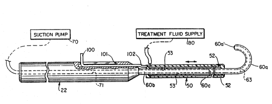
Referring to Fig. 2, a schematic dia~ram of a pre-
ferred embodiment of the instrument for irrigating and aspirat-
ing a material is illustrated.
A tube 60 is formed of a straight shank portion 60b
at the end thereof which is connected to a handpiece 22. At the
other, or operative, end of the tube 60, is a tip portion 60a.
Tip portion 60a is resiliently deformable from a hooked shape
into a straight shape. Preferably, in hooked shape, the tip
portion 60a may have a bend of up to about 180 degrees. It
SUE~STITIJTE St~EET
~-~92/16246 2 J. G 5 ~ J~ PCT/US91/081
will be appreciated that the hooked portion may be formed to
bend in varying angles up to about 180 degrees.
The tube 60, preferably, has an outer diameter of no
more than approximately lmm and has a conduit 63 extending
through the length of the tube to opening 60a'. Tube 60 is
connected, through the handpiece 22, to a source of vacuum 70,
for aspirating material through opening 60a~. For this pur-
pose, the source of vacuum 70 may be of the type shown in U.S.
Patent No. 3, 5ag,363 ~ormed as a vacuum pump.
Preferably, the tip portion 60a is formed of a resil-
ient material, such as polypropylene or other plastic material.
The resilient material may be deformed upon the application of
an outside force, as is described in detail below. ~urther,
the resilient material of the tip portion 60a has a memory
(meaning that the tube portion 60a, forming the operative tip
of the instrument, is made of a material which will return to
its natural predetermined hooked shape after externally applied
straightening force is removed).
The free end of the tip portion 60a may be of rounded
shape to avoid injury to the tissue when the tip is inserted
into the eye through incisions made in the cornea and in the
anterior wall capsule.
In the preferred embodiment, a tubular sleeve 50
forms a hollow cylinder around the tube 60 for housing a
portion of the tube 60. The tubular sleeve 50 has an inner
diameter which is only slightly larger than the outer diameter
of the tube 60 so that sleeve 50 will slide along tube 60. The
tubular sleeve 50 is formed of a rigid material. It will be
appreciated that the rigid material of the sleeve can be metal,
teflon, or other plastic materials, as are known in the art and
suitable for use in surgical procedures of the eye.
The tubular sleeve 50 may be slid longitudinally
along the tube 60 and selectively moved onto and off the
flexible tip portion 60a. As the tubular sleeve 50 is slid
onto the tip portion 60a, the sleeve acts as an outside force
SUBSTITUTE SHEET
~ 3 P~T/US91/08144
to press against the natural bend of the hooked portion,
whereby the bend in the hook tip portion 60a is straightened.
As illustrated in Fig. 3, once the tubular sleeve is moved over
and surrounds the hooked tip portion 60a, the hooked portion
60a is deformed and becomes a straight tip.
In a preferred embodiment, the sleeve 50 has irrigat-
ing openings 52 provided at the end thereof nearest the opera-
tive end of the instrument and a conduit extending through the
sleeve. A source of irrigating fluid 80, such as saline
solution or medicated solution, can be pumped to the irrigating
openings 52, via a conduit 53 in the sleeve, so as to be
delivered to the area to be irrigated. In an alternative
embodiment (not shown), the source of irrigating fluid 80 may
be supplied to the handpiece 22 and through a conduit in the
tube 60 to the operative end of the instrument.
A control arm lO0 may be provided in the handpiece 22
for controlling the sliding of the tubular sleeve 50 along the
tube 60. When the control arm (Fig. 2) is pushed forwardly in
its slot lOl, the connecting portion 102 causes the tubular
sleeve 50 to move in a direction from the straight shank
portion 60b of tube 60 to the tip portion 60a. Thereby the
tubular sleeve 50 can be moved onto the hooked portion 60a for
deforming the hooked portion as described above. Retracting
arm lO0 moves the tubular sleeve 50 in a direction from the
hooked tip portion 60a to the straight shank portion 60b of the
tube so that the tubular sleeve 50 is moved off the hooked
portion 60a.
When the tubular sleeve portion 50 is moved over the
hooked portion 60a it straightens out the hooked portion, as
shown in Fig. 3. In this configuration, the tip portion of the
tube 60a may be easily inserted through the small incision 14
in the cornea and into the posterior capsule 12, as shown in
Fig. 4. The incision need only be about l to 3mm in length to
provide proper access for the operative end of the tube with
the tip portion 60a in straight-tip condition i.e. surrounded
SUBSTITUTE SHEET
2~ i 5
~ ~92/16246 PCT/US91/0~144
by sleeve 50. As is known in the art, a small aperture may be
surgically made in the anterior wall of capsule 12. The
operative end of the tube 60 may be directed by manipulating
the handpiece 22 so that the tip 60a, with the sleeve 50 over
it, may reach the central regions of the posterior capsule 12b.
Afterwards, the sleeve 50 may be retracted off the portion 60a
onto the straight shank portion 60b of t:ube 60 as illustrated
in Fig. 2, whereby the tip portion 60a again automatically-
because of the memory of the material of portion 60a - assumes
the hooked configuration of predetermined angle. It will be
seen that in this configuration the operative end of the hooked
tip portion 60a will extend around the remaining peripheral
portions of the anterior wall of the capsule and reach into the
otherwise inaccessible interior peripheral regions of the
capsule as shown in Fig. 4. Thus, in this configuration the
handpiece 22 may be manipulated to direct the operat:Lve end of
the hooked tip portion 60a around to the different peripheral
inner regions of the capsule 12a.
The separated unwanted tissue and excess treatment
fluid may be aspirated with suction pump 70 through conduit 71
in the tube 60. Upon removing the unwanted tissue and fluid,
the tubular sleeve 50 may again be moved onto the tip portion
60a so that the hook shape will be straightened out and the
instrument may be easily withdrawn from the eye.
In a preferred embodiment the tube portion 60b is of
rigid construction, preferably polymethylmethacrylate and
e~tends from the end at which tube 60 is fixed to the handpiece
22, to a region 60c which is located within the confines of
sleeve 50 in all positions o~ sleeve 50 on tube 60. Tip
portion 60a which is preferably preshaped (into hooked config-
uration) polypropylene is integrally connected to portion 60b
at 60c.
The specification and drawings are set forth by way
of illustration and not limitation, and various modifications
may be made therein without departing from the spirit of the
SUBSTITUTE SHEET
~ PCT/US91/081M
WO92/16246 ~
invention which is to be limited solely by the scope of the
claims.
SUBSTITUTE SHEET