Language selection

Search

Patent 2106923 Summary

Third-party information liability

Some of the information on this Web page has been provided by external sources. The Government of Canada is not responsible for the accuracy, reliability or currency of the information supplied by external sources. Users wishing to rely upon this information should consult directly with the source of the information. Content provided by external sources is not subject to official languages, privacy and accessibility requirements.

Claims and Abstract availability

Any discrepancies in the text and image of the Claims and Abstract are due to differing posting times. Text of the Claims and Abstract are posted:

  • At the time the application is open to public inspection;
  • At the time of issue of the patent (grant).
(12) Patent: (11) CA 2106923
(54) English Title: VALVE
(54) French Title: ROBINET
Status: Expired and beyond the Period of Reversal
Bibliographic Data
(51) International Patent Classification (IPC):
  • F16K 25/00 (2006.01)
  • E21B 34/06 (2006.01)
  • E21B 34/14 (2006.01)
  • F16K 05/06 (2006.01)
  • F16K 05/18 (2006.01)
(72) Inventors :
  • COX, DON C. (United States of America)
(73) Owners :
  • HALLIBURTON ENERGY SERVICES, INC.
(71) Applicants :
  • HALLIBURTON ENERGY SERVICES, INC. (United States of America)
(74) Agent: RICHES, MCKENZIE & HERBERT LLP
(74) Associate agent:
(45) Issued: 1999-09-21
(22) Filed Date: 1993-09-24
(41) Open to Public Inspection: 1994-03-25
Examination requested: 1996-01-16
Availability of licence: N/A
Dedicated to the Public: N/A
(25) Language of filing: English

Patent Cooperation Treaty (PCT): No

(30) Application Priority Data:
Application No. Country/Territory Date
07/949,939 (United States of America) 1992-09-24

Abstracts

English Abstract


A metal valve, has a body with flow passages and
curved internal sealing surfaces and a valve member with
a flow passage and external curved sealing surfaces.
Both the body and valve member sealing surfaces axe
curved as a portion of the involute of a circle and are
sealingly engageable. The valve member is mounted in the
body for rotation between open and closed positions,
permitting and preventing flow through valve.


Claims

Note: Claims are shown in the official language in which they were submitted.

9
CLAIMS
1. A valve comprising:
(a) a body having inlet and outlet flow passages and
inlet and outlet flow passage sealing surfaces
therein, said inlet and outlet sealing surfaces
formed as a portion of the curve of an involute
of a circle; and
(b) a valve member having a flow passage
therethrough mounted for rotation between open
and closed positions in said body, said valve
member having sealing surfaces thereon, each
said sealing surface formed as a portion of the
curve of an involute of a circle, said valve
member sealing surfaces sealingly engageable
with said body inlet and outlet sealing
surfaces.
2. The valve of claim 1 wherein the curve of an
involute of a circle is defined in polar coordinates by:
<IMG>
wherein: A = radius of the base circle,
R = radius from the centre of the base circle to
a point on the involute, and
~ = angle of revolution about the centre of the
base circle from the starting point of the
involute to R.

10
3. A valve comprising:
(a) a body having inlet and outlet flow passages and
inlet and outlet sealing surfaces therein, said
inlet and outlet sealing surfaces formed as a
portion of the curve of an involute of a circle;
(b) a valve member having a flow passage
therethrough and sealing surfaces thereon, each
said sealing surface formed as a portion of the
curve of an involute of a circle, said valve
member sealing surfaces sealingly engageable
with said body sealing surfaces and said valve
member rotatably mounted in said body;
(c) a bonnet connected in and sealed to said body;
and
(d) means for sealing said valve member in said body
and bonnet.
4. The valve of claim 3 wherein the body, valve
member and bonnet are metal.
5. The valve of claim 3 or claim 4 wherein the
bonnet is sealed to the body with a metal seal and the
means for sealing the valve member in the body and bonnet
are metal seals.
6. A valve comprising:
(a) a metal body having flow passages and involute
curved sealing surfaces therein;

11
(b) a metal valve member having a flow passage
therethrough and involute curved sealing
surfaces thereon, said valve member curved
sealing surfaces sealingly engageable with said
body curved sealing surfaces, said valve member
rotatably mounted and sealed in said body with a
metal seal, said valve member and body involute
sealing surfaces formed as a portion of the
involute of a circle, said involute is defined
in polar coordinates by:
<IMG>
where: A = radius of the base circle,
R = radius from the centre of the base circle to
a point on the involute, and
~ = angle of revolution about the centre of the
base circle from the starting point of the
involute to R; and
(c) a metal bonnet connected in and sealed to said
body with a metal seal, said valve member sealed
for rotation in said bonnet with a metal seal.
7. A valve having a longitudinal flow passage
therethrough, said valve comprising:
(a) a connector having a thread thereon and recesses
therein, said connector sealably connected to
(b) a cylindrical body having a wall with flow
passages therethrough and sealing surfaces
therein, said sealing surfaces formed as a

12
portion of the curve of an involute of a circle,
said body sealably connected to a
(c) lower body having a thread thereon;
(d) a valve member mounted for rotation in said
lower body, said valve member having flow
passages therethrough and sealing surfaces
thereon, said sealing surfaces formed as a
portion of the curve of an involute of a circle,
said valve member sealing surfaces sealingly
engageable with said body sealing surfaces; and
(e) means for rotating said valve member between
open position, where said body and valve member
flow passages are aligned to permit flow between
said valve longitudinal flow passage and outside
said valve and closed position, where said valve
member sealing surfaces sealingly engage said
body sealing surfaces and close said body and
valve member flow passages to flow.
8. The valve of claim 7 wherein the means for
rotating the valve member comprises:
(a) projections on the valve member;
(b) the connector recesses, wherein a rotary
positioning tool is connectable; and
(c) a rotatable member disposed in said body, said
rotatable member having upper and lower
projections, said lower projections meshing with
said valve member projections.

13
9. The valve of claim 7 wherein the valve member
sealing surfaces and body sealing surfaces are formed as
a portion of the curve of an involute of a circle, said
involute is defined in polar coordinates by:
<IMG>
where: A = radius of the base circle,
R = radius from the centre of the base circle to
a point on the involute, and
~ = angle of revolution about the centre of the
base circle from the starting point of the
involute to R.
10. The valve of any one of claims 1, 2, 7, 8 or 9
wherein the body and valve member are metal.
11. The valve of any one of claims 7 to 9 wherein
the body, valve member, connector and lower body are
metal.
12. A valve comprising:
(a) a body having flow passages therethrough and
sealing surfaces therein, said sealing surfaces
formed as a portion of the curve of an involute
of a circle;
(b) a valve member mounted for rotation in said
body, said valve member having flow passages
therethrough and sealing surfaces thereon, said
sealing surfaces formed as a portion of the

14
curve of an involute of a circle, said sealing
surfaces sealingly engageable with said body
sealing surfaces; and
(c) means for rotating said valve member between
open position, where said body and said valve
member flow passages are aligned, and closed
position, where said valve member sealing
surfaces sealingly engage said body sealing
surfaces and close said body and valve member
flow passages to flow.
13. The valve of claim 12 further including a
connector and a lower body for connecting the body into a
flow conduit, said connector having recesses therein.
14. The valve of claim 12 or claim 13 wherein the
means for rotating the valve member between open and
closed positions comprises:
(a) recesses in the connector;
(b) projections on the valve member; and
(c) a rotatable member in the body, said rotatable
member having projections meshing with said
valve member projections.
15. The valve of claim 12 or claim 13 wherein the
rotatable member further includes projections not meshing
with the valve member projections.

15
16. A valve having a longitudinal flow passage
therethrough, said valve comprising:
(a) a metal connector having a thread thereon and
recesses therein for connection of a positioning
tool, said connector sealably connected to
(b) a cylindrical metal body having a wall with flow
passages therethrough and involute curved
sealing surfaces in said body, said body
sealably connected to a
(c) metal lower body having a thread thereon and a
bearing surface therein;
(d) a metal valve member mounted for rotation on
said lower body bearing surface, said valve
member having flow passages therethrough,
involute curved sealing surfaces and projections
thereon, said valve member curved sealing
surfaces sealingly engageable with said curved
body sealing surfaces, said valve member and
body sealing surfaces curved as a portion of an
involute of a circle which is defined in polar
coordinates by:
<IMG>
where: A = radius of the base circle,
R = radius from the centre of the base circle to
a point on the involute, and
~ = angle of revolution about the centre of the
base circle from the starting point of the
involute to R; and

16
(e) means for rotating said valve member between
open position, aligning said valve member flow
passages with said body flow passages and
permitting flow between said valve longitudinal
flow passage and outside the valve and closed
position, preventing flow between said valve
longitudinal flow passage and outside the
valve, said means for rotating said valve
member comprising:
said connector recesses,
a rotatable member in said body,
said rotatable member having projections on one end
meshing with said valve member projections and
projections on the other end for engagement by a
rotatable positioning tool.

Description

Note: Descriptions are shown in the official language in which they were submitted.


I
VALVE
This application pertains to valves and
particularly pertains to valves having a valve member
which is mounted in a body and rotated between open and
closed positions.
Quite a number of valves have been developed
which utilize resilient sealing materials for sealing
between internal valve parts and metal valves and metal
seats which rub on each other through the full arc as the
valve member is rotated between open and closed
positions. The resilient sealing materials often
deteriorate rapidly as affected by high temperatures,
chemical action and possibly erosion to a condition in
which they no longer seal internal valve parts to one
another. After metal valves and seats rub on each other
through full turning arcs numerous times, metal sealing
surfaces tend to gall ruining orie or both of the sealing

--,
210~~2~
2
most desirable curved surface for metal sealing surfaces.
The involute of a circle was found to have all the
required characteristics. The location of points on the
involute curve was calculated and it was found there were
a number of existing manufacturing processes which could
be used to form involute curves on metal valve members
and in metal valve bodies.
A valve according to the present invention
therefore comprises a body having flow passages
therethrough and comprising a valve seat having sealing
surfaces formed as a portion of an involute curve, and a
valve member having a flow passage therethrough mounted
for rotation between open and closed positions in said
body, said valve member having sealing surfaces formed as
a portion of an involute curve, said valve member sealing
surfaces sealingly engageable with said seat member
sealing surfaces.
The valves may utilize a metal valve member and
a metal seat and have no resilient material seals which
may deteriorate. The seat may be formed by integral
sealing surfaces in the valve body. The sealing surfaces
on the valve member and seat may be Formed according to
the mathematical formula for the involute of a circle,
which is defined in polar coordinates by:
a ~ Rz/AZ _ 1 _ ARCTAN ~RZ/AZ - 1
where: A = radius of the base circle, ,.'.

3
R = radius from the centre of the base circle to
a point on the involute, and
a = angle of revolution about the centre of the
base circle from the starting point of the
involute to R.
By rotating the valve member relative to sealing
surfaces in the body, flow passages in the body are
closed or opened to flow. The involute shape of the
sealing surfaces ensures sealing engagement throughout
the entire area of contact between the two sealing
surfaces and provides immediate separation of the sealing
surfaces on any,rotation, which prevents rubbing of one
sealing surface on the other throughout the angle over
which the valve member is rotated. Tt should be easily

4
curved sealing surfaces on a rotatable valve member and
in a body in which the valve member is rotated from the
closed to the open position, a clearance between the
valve member and body sealing surces can be created on
any rotation of the valve member prevents erosion or flow
cutting of the sealing surfaces and the valve member
sealing surfaces do not rub on the body sealing surfaces
as the valve member is rotated to the open position and
back to the closed position.
The invention can also provide an all metal
valve which consistently requires little torque to rotate
the valve member from the closed to the open position and
back to the closed position, regardless of how high the
pressure differential is across the closed valve.
Embodiments of the invention will be described
in more detail with reference to the accompanying
drawings, in which:
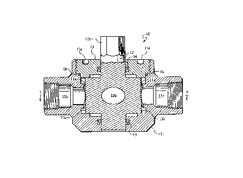
Fig. 1 is a plan view of a valve according to
the invention;
Fig. 2 is an axial section on the line 2-2 in
Fig. 1;
Figs. 3 to 5 are transverse sections on the line
3-3 in Fig. 2; showing the valve in different rotated
positions;
Fig. 6 illustrates another embodiment of valve
according to the invention in an axial section;
Fig. 7 is a transverse section on the line 7-7
in Fig. 6; and

5
Fig. 8 and 9 are transverse sections on the
line 8-8 in Fig. 6 showing the valve in different
positions of rotation.
Fig. 1 shows a valve 10 which includes a body 11
and a valve member 12 rotatably mounted in the body. The
valve member has a stem with wrench flats 12a, a through
flow passage 12b and two identical sealing surfaces 12c
- see Fig. 2. The valve member is positioned for rotation
in the body by a bonnet 13 secured in the body and the valve
member stem is sealed to the bonnet by a metal seal
14 and to the body by a metal seal 15. The bonnet has
holes 13a into which a spanner wrench may be fitted to
secure the bonnet in the body.
The bonnet is sealed to the body by another
metal seal 16. In the body are two identical curved
sealing surfaces 11a, which are sealingly engageable with
curved valve member sealing surfaces 12c, and flow
passages 11b and 11c. Sealing surfaces 11a and 12c are
formed as portions of involute curves according to the
previously stated formula (see Figs. 3, 4 and 5). Valve
member sealing surfaces sealingly engage body sealing
surfaces when the valve member is rotated to closed
position as shown in Fig. 5, and flow between flow
passages 11b and 11c through flow passage 12b is
prevented.
When the valve member is rotated from closed
position toward open position as shown in Fig. 3, the
valve sealing surfaces immediately move away from the

~~ os~z~
6
body sealing surfaces a clearance c distance and no
rubbing occurs between the sealing surfaces as the valve
member is rotated to full open position shown in Fig. 4.
When the valve is open, flow may occur between flow
passages 11b and 11c through flow passage 12b.
Clearance c between valve member sealing
surfaces and body sealing surfaces is established
immediately on rotation of the valve member and increases
to a maximum when the valve member is in open position as
shown in Figs. 3 and 4.
The embodiment of valve 17 shown in Fig. 6 is
arranged to be connected in a well flow conduit, lowered
into a larger well conduit and be rotated between open
and closed positions by a rotary positioning tool (not
shown), which is lowered into the conduit and engages the
valve. The outside diameter of valve 17 has been reduced
and the inside diameter has been increased for
compatibility with standard well conduit sizes.
Valve 17 includes a connector 18 having an
appropriate thread 18a for connection into a well conduit
and recesses 18b (Fig. 7) into which the positioning tool
connects for operation to rotate the valve member. The
connector is sealably connected to a body 19 having flow
passages 19a. znside the body are curved sealing
surfaces 19b, each curved as a portion of an involute
curve according to the previously stated formula, see
F~.gs. 8 and 9. A lower body 20 is sealably connected to
body 19 and has an appropriate thread 20a for connection

21~~~2
7
into a conduit and a bearing surface 20b. Mounted for
.. rotation on the bearing surface and in the body is a
valve member 21. The valve member has sealing surfaces
21a, each surface is formed as a portion of an involute
curve, also according to the previously stated formula,
which is sealingly engageable with body involute curve
sealing surfaces 19b. Valve member 21 also has flow
passages 21b and is connected to a rotatable member 22
through meshing projections 21c on the valve member and
22a on the rotatable member. The rotatable member also
has projections 22b engageable by a rotary positioning
tool, for rotating member 22 and valve member 21 between
open and closed,positions in bodies 19 and 20. Valve 17
also has a longitudinal through flow passage 23.
When the rotatable member is rotated clockwise
by the positioning tool, the valve member is rotated to
closed position as shown in Fig. 8 and flow between flow
passage 23 through flow passages 21b and outside the
valve 17 is prevented. When the positioning tool is
operated to rotate member 22 and valve member 21
counterclockwise, flow passages 21b are aligned with flow
passages 19a as shown in Fig. 9 and flow may occur
between valve flow passage 23 through passages 21b and
outside the valve.
Testing to date of a valve with involute sealing
surfaces revealed opening and closing the valve numerous
times against very high pressure differentials has not
damaged the involute sealing surfaces or degraded their
;' ',: :' . ,, ~ - .' '.' .. : : :: ' , ; :a ~ ,':;~ ; ,. .,: ::v,., ,:..' :
., , ~~' :.. ,: . ~ .
.;~:, '.'. : .' ';..: , ,,

2~4~~23
8
sealing ability. A surprise finding during tests was
that the torque to open the valve remains very low and
essentially the same no matter how high the pressure
differential across the closed valve.
Also, as clearance between the valve member
sealing surfaces and body sealing surfaces occurs
immediately on any rotation of the valve member and
increases to a maximum when the valve member is in open
position, flow cutting by flow between the valve sealing
surfaces and body sealing surfaces has been found to be
nil.

Representative Drawing
A single figure which represents the drawing illustrating the invention.
Administrative Status

2024-08-01:As part of the Next Generation Patents (NGP) transition, the Canadian Patents Database (CPD) now contains a more detailed Event History, which replicates the Event Log of our new back-office solution.

Please note that "Inactive:" events refers to events no longer in use in our new back-office solution.

For a clearer understanding of the status of the application/patent presented on this page, the site Disclaimer , as well as the definitions for Patent , Event History , Maintenance Fee  and Payment History  should be consulted.

Event History

Description Date
Inactive: IPC from MCD 2006-03-11
Time Limit for Reversal Expired 2002-09-24
Letter Sent 2001-09-24
Grant by Issuance 1999-09-21
Inactive: Cover page published 1999-09-20
Inactive: Office letter 1999-07-09
Inactive: Final fee received 1999-05-14
Inactive: Single transfer 1999-05-14
Pre-grant 1999-05-14
Letter Sent 1999-03-08
Notice of Allowance is Issued 1999-03-08
Inactive: Status info is complete as of Log entry date 1999-03-01
Inactive: Application prosecuted on TS as of Log entry date 1999-03-01
Inactive: Approved for allowance (AFA) 1999-02-08
All Requirements for Examination Determined Compliant 1996-01-16
Request for Examination Requirements Determined Compliant 1996-01-16
Application Published (Open to Public Inspection) 1994-03-25

Abandonment History

There is no abandonment history.

Maintenance Fee

The last payment was received on 1999-08-23

Note : If the full payment has not been received on or before the date indicated, a further fee may be required which may be one of the following

  • the reinstatement fee;
  • the late payment fee; or
  • additional fee to reverse deemed expiry.

Patent fees are adjusted on the 1st of January every year. The amounts above are the current amounts if received by December 31 of the current year.
Please refer to the CIPO Patent Fees web page to see all current fee amounts.

Fee History

Fee Type Anniversary Year Due Date Paid Date
MF (application, 4th anniv.) - standard 04 1997-09-24 1997-08-20
MF (application, 5th anniv.) - standard 05 1998-09-24 1998-08-27
Registration of a document 1999-05-14
Final fee - standard 1999-05-14
MF (application, 6th anniv.) - standard 06 1999-09-24 1999-08-23
MF (patent, 7th anniv.) - standard 2000-09-25 2000-08-16
Owners on Record

Note: Records showing the ownership history in alphabetical order.

Current Owners on Record
HALLIBURTON ENERGY SERVICES, INC.
Past Owners on Record
DON C. COX
Past Owners that do not appear in the "Owners on Record" listing will appear in other documentation within the application.
Documents

To view selected files, please enter reCAPTCHA code :


To view images, click a link in the Document Description column. To download the documents, select one or more checkboxes in the first column and then click the "Download Selected in PDF format (Zip Archive)" or the "Download Selected as Single PDF" button.

List of published and non-published patent-specific documents on the CPD .

If you have any difficulty accessing content, you can call the Client Service Centre at 1-866-997-1936 or send them an e-mail at CIPO Client Service Centre.


Document
Description 
Date
(yyyy-mm-dd) 
Number of pages   Size of Image (KB) 
Representative drawing 1999-09-15 1 23
Claims 1994-05-24 8 350
Description 1994-05-24 8 371
Drawings 1994-05-24 4 193
Abstract 1994-05-24 1 26
Claims 1999-01-26 8 224
Commissioner's Notice - Application Found Allowable 1999-03-07 1 164
Maintenance Fee Notice 2001-10-21 1 178
Correspondence 1999-05-13 2 64
Correspondence 1999-07-08 1 7
Fees 2016-07-06 1 75
Fees 1995-08-23 1 59
PCT Correspondence 1993-12-19 1 33
Prosecution correspondence 1996-01-15 1 36
Courtesy - Office Letter 1996-03-07 1 32
Prosecution correspondence 1998-05-19 2 38
Examiner Requisition 1998-05-07 1 28
Prosecution correspondence 1996-06-13 2 40