Sélection de la langue

Search

Sommaire du brevet 2106923 

Énoncé de désistement de responsabilité concernant l'information provenant de tiers

Une partie des informations de ce site Web a été fournie par des sources externes. Le gouvernement du Canada n'assume aucune responsabilité concernant la précision, l'actualité ou la fiabilité des informations fournies par les sources externes. Les utilisateurs qui désirent employer cette information devraient consulter directement la source des informations. Le contenu fourni par les sources externes n'est pas assujetti aux exigences sur les langues officielles, la protection des renseignements personnels et l'accessibilité.

Disponibilité de l'Abrégé et des Revendications

L'apparition de différences dans le texte et l'image des Revendications et de l'Abrégé dépend du moment auquel le document est publié. Les textes des Revendications et de l'Abrégé sont affichés :

  • lorsque la demande peut être examinée par le public;
  • lorsque le brevet est émis (délivrance).
(12) Brevet: (11) CA 2106923
(54) Titre français: ROBINET
(54) Titre anglais: VALVE
Statut: Périmé et au-delà du délai pour l’annulation
Données bibliographiques
(51) Classification internationale des brevets (CIB):
  • F16K 25/00 (2006.01)
  • E21B 34/06 (2006.01)
  • E21B 34/14 (2006.01)
  • F16K 05/06 (2006.01)
  • F16K 05/18 (2006.01)
(72) Inventeurs :
  • COX, DON C. (Etats-Unis d'Amérique)
(73) Titulaires :
  • HALLIBURTON ENERGY SERVICES, INC.
(71) Demandeurs :
  • HALLIBURTON ENERGY SERVICES, INC. (Etats-Unis d'Amérique)
(74) Agent: RICHES, MCKENZIE & HERBERT LLP
(74) Co-agent:
(45) Délivré: 1999-09-21
(22) Date de dépôt: 1993-09-24
(41) Mise à la disponibilité du public: 1994-03-25
Requête d'examen: 1996-01-16
Licence disponible: S.O.
Cédé au domaine public: S.O.
(25) Langue des documents déposés: Anglais

Traité de coopération en matière de brevets (PCT): Non

(30) Données de priorité de la demande:
Numéro de la demande Pays / territoire Date
07/949,939 (Etats-Unis d'Amérique) 1992-09-24

Abrégés

Abrégé anglais


A metal valve, has a body with flow passages and
curved internal sealing surfaces and a valve member with
a flow passage and external curved sealing surfaces.
Both the body and valve member sealing surfaces axe
curved as a portion of the involute of a circle and are
sealingly engageable. The valve member is mounted in the
body for rotation between open and closed positions,
permitting and preventing flow through valve.

Revendications

Note : Les revendications sont présentées dans la langue officielle dans laquelle elles ont été soumises.


9
CLAIMS
1. A valve comprising:
(a) a body having inlet and outlet flow passages and
inlet and outlet flow passage sealing surfaces
therein, said inlet and outlet sealing surfaces
formed as a portion of the curve of an involute
of a circle; and
(b) a valve member having a flow passage
therethrough mounted for rotation between open
and closed positions in said body, said valve
member having sealing surfaces thereon, each
said sealing surface formed as a portion of the
curve of an involute of a circle, said valve
member sealing surfaces sealingly engageable
with said body inlet and outlet sealing
surfaces.
2. The valve of claim 1 wherein the curve of an
involute of a circle is defined in polar coordinates by:
<IMG>
wherein: A = radius of the base circle,
R = radius from the centre of the base circle to
a point on the involute, and
~ = angle of revolution about the centre of the
base circle from the starting point of the
involute to R.

10
3. A valve comprising:
(a) a body having inlet and outlet flow passages and
inlet and outlet sealing surfaces therein, said
inlet and outlet sealing surfaces formed as a
portion of the curve of an involute of a circle;
(b) a valve member having a flow passage
therethrough and sealing surfaces thereon, each
said sealing surface formed as a portion of the
curve of an involute of a circle, said valve
member sealing surfaces sealingly engageable
with said body sealing surfaces and said valve
member rotatably mounted in said body;
(c) a bonnet connected in and sealed to said body;
and
(d) means for sealing said valve member in said body
and bonnet.
4. The valve of claim 3 wherein the body, valve
member and bonnet are metal.
5. The valve of claim 3 or claim 4 wherein the
bonnet is sealed to the body with a metal seal and the
means for sealing the valve member in the body and bonnet
are metal seals.
6. A valve comprising:
(a) a metal body having flow passages and involute
curved sealing surfaces therein;

11
(b) a metal valve member having a flow passage
therethrough and involute curved sealing
surfaces thereon, said valve member curved
sealing surfaces sealingly engageable with said
body curved sealing surfaces, said valve member
rotatably mounted and sealed in said body with a
metal seal, said valve member and body involute
sealing surfaces formed as a portion of the
involute of a circle, said involute is defined
in polar coordinates by:
<IMG>
where: A = radius of the base circle,
R = radius from the centre of the base circle to
a point on the involute, and
~ = angle of revolution about the centre of the
base circle from the starting point of the
involute to R; and
(c) a metal bonnet connected in and sealed to said
body with a metal seal, said valve member sealed
for rotation in said bonnet with a metal seal.
7. A valve having a longitudinal flow passage
therethrough, said valve comprising:
(a) a connector having a thread thereon and recesses
therein, said connector sealably connected to
(b) a cylindrical body having a wall with flow
passages therethrough and sealing surfaces
therein, said sealing surfaces formed as a

12
portion of the curve of an involute of a circle,
said body sealably connected to a
(c) lower body having a thread thereon;
(d) a valve member mounted for rotation in said
lower body, said valve member having flow
passages therethrough and sealing surfaces
thereon, said sealing surfaces formed as a
portion of the curve of an involute of a circle,
said valve member sealing surfaces sealingly
engageable with said body sealing surfaces; and
(e) means for rotating said valve member between
open position, where said body and valve member
flow passages are aligned to permit flow between
said valve longitudinal flow passage and outside
said valve and closed position, where said valve
member sealing surfaces sealingly engage said
body sealing surfaces and close said body and
valve member flow passages to flow.
8. The valve of claim 7 wherein the means for
rotating the valve member comprises:
(a) projections on the valve member;
(b) the connector recesses, wherein a rotary
positioning tool is connectable; and
(c) a rotatable member disposed in said body, said
rotatable member having upper and lower
projections, said lower projections meshing with
said valve member projections.

13
9. The valve of claim 7 wherein the valve member
sealing surfaces and body sealing surfaces are formed as
a portion of the curve of an involute of a circle, said
involute is defined in polar coordinates by:
<IMG>
where: A = radius of the base circle,
R = radius from the centre of the base circle to
a point on the involute, and
~ = angle of revolution about the centre of the
base circle from the starting point of the
involute to R.
10. The valve of any one of claims 1, 2, 7, 8 or 9
wherein the body and valve member are metal.
11. The valve of any one of claims 7 to 9 wherein
the body, valve member, connector and lower body are
metal.
12. A valve comprising:
(a) a body having flow passages therethrough and
sealing surfaces therein, said sealing surfaces
formed as a portion of the curve of an involute
of a circle;
(b) a valve member mounted for rotation in said
body, said valve member having flow passages
therethrough and sealing surfaces thereon, said
sealing surfaces formed as a portion of the

14
curve of an involute of a circle, said sealing
surfaces sealingly engageable with said body
sealing surfaces; and
(c) means for rotating said valve member between
open position, where said body and said valve
member flow passages are aligned, and closed
position, where said valve member sealing
surfaces sealingly engage said body sealing
surfaces and close said body and valve member
flow passages to flow.
13. The valve of claim 12 further including a
connector and a lower body for connecting the body into a
flow conduit, said connector having recesses therein.
14. The valve of claim 12 or claim 13 wherein the
means for rotating the valve member between open and
closed positions comprises:
(a) recesses in the connector;
(b) projections on the valve member; and
(c) a rotatable member in the body, said rotatable
member having projections meshing with said
valve member projections.
15. The valve of claim 12 or claim 13 wherein the
rotatable member further includes projections not meshing
with the valve member projections.

15
16. A valve having a longitudinal flow passage
therethrough, said valve comprising:
(a) a metal connector having a thread thereon and
recesses therein for connection of a positioning
tool, said connector sealably connected to
(b) a cylindrical metal body having a wall with flow
passages therethrough and involute curved
sealing surfaces in said body, said body
sealably connected to a
(c) metal lower body having a thread thereon and a
bearing surface therein;
(d) a metal valve member mounted for rotation on
said lower body bearing surface, said valve
member having flow passages therethrough,
involute curved sealing surfaces and projections
thereon, said valve member curved sealing
surfaces sealingly engageable with said curved
body sealing surfaces, said valve member and
body sealing surfaces curved as a portion of an
involute of a circle which is defined in polar
coordinates by:
<IMG>
where: A = radius of the base circle,
R = radius from the centre of the base circle to
a point on the involute, and
~ = angle of revolution about the centre of the
base circle from the starting point of the
involute to R; and

16
(e) means for rotating said valve member between
open position, aligning said valve member flow
passages with said body flow passages and
permitting flow between said valve longitudinal
flow passage and outside the valve and closed
position, preventing flow between said valve
longitudinal flow passage and outside the
valve, said means for rotating said valve
member comprising:
said connector recesses,
a rotatable member in said body,
said rotatable member having projections on one end
meshing with said valve member projections and
projections on the other end for engagement by a
rotatable positioning tool.

Description

Note : Les descriptions sont présentées dans la langue officielle dans laquelle elles ont été soumises.

I
VALVE
This application pertains to valves and
particularly pertains to valves having a valve member
which is mounted in a body and rotated between open and
closed positions.
Quite a number of valves have been developed
which utilize resilient sealing materials for sealing
between internal valve parts and metal valves and metal
seats which rub on each other through the full arc as the
valve member is rotated between open and closed
positions. The resilient sealing materials often
deteriorate rapidly as affected by high temperatures,
chemical action and possibly erosion to a condition in
which they no longer seal internal valve parts to one
another. After metal valves and seats rub on each other
through full turning arcs numerous times, metal sealing
surfaces tend to gall ruining orie or both of the sealing

--,
210~~2~
2
most desirable curved surface for metal sealing surfaces.
The involute of a circle was found to have all the
required characteristics. The location of points on the
involute curve was calculated and it was found there were
a number of existing manufacturing processes which could
be used to form involute curves on metal valve members
and in metal valve bodies.
A valve according to the present invention
therefore comprises a body having flow passages
therethrough and comprising a valve seat having sealing
surfaces formed as a portion of an involute curve, and a
valve member having a flow passage therethrough mounted
for rotation between open and closed positions in said
body, said valve member having sealing surfaces formed as
a portion of an involute curve, said valve member sealing
surfaces sealingly engageable with said seat member
sealing surfaces.
The valves may utilize a metal valve member and
a metal seat and have no resilient material seals which
may deteriorate. The seat may be formed by integral
sealing surfaces in the valve body. The sealing surfaces
on the valve member and seat may be Formed according to
the mathematical formula for the involute of a circle,
which is defined in polar coordinates by:
a ~ Rz/AZ _ 1 _ ARCTAN ~RZ/AZ - 1
where: A = radius of the base circle, ,.'.

3
R = radius from the centre of the base circle to
a point on the involute, and
a = angle of revolution about the centre of the
base circle from the starting point of the
involute to R.
By rotating the valve member relative to sealing
surfaces in the body, flow passages in the body are
closed or opened to flow. The involute shape of the
sealing surfaces ensures sealing engagement throughout
the entire area of contact between the two sealing
surfaces and provides immediate separation of the sealing
surfaces on any,rotation, which prevents rubbing of one
sealing surface on the other throughout the angle over
which the valve member is rotated. Tt should be easily

4
curved sealing surfaces on a rotatable valve member and
in a body in which the valve member is rotated from the
closed to the open position, a clearance between the
valve member and body sealing surces can be created on
any rotation of the valve member prevents erosion or flow
cutting of the sealing surfaces and the valve member
sealing surfaces do not rub on the body sealing surfaces
as the valve member is rotated to the open position and
back to the closed position.
The invention can also provide an all metal
valve which consistently requires little torque to rotate
the valve member from the closed to the open position and
back to the closed position, regardless of how high the
pressure differential is across the closed valve.
Embodiments of the invention will be described
in more detail with reference to the accompanying
drawings, in which:
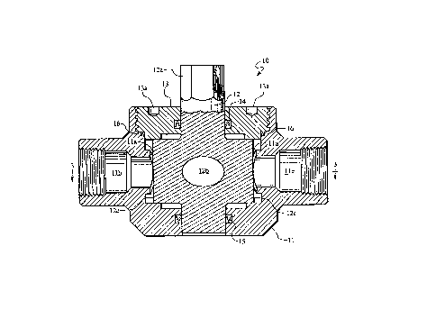
Fig. 1 is a plan view of a valve according to
the invention;
Fig. 2 is an axial section on the line 2-2 in
Fig. 1;
Figs. 3 to 5 are transverse sections on the line
3-3 in Fig. 2; showing the valve in different rotated
positions;
Fig. 6 illustrates another embodiment of valve
according to the invention in an axial section;
Fig. 7 is a transverse section on the line 7-7
in Fig. 6; and

5
Fig. 8 and 9 are transverse sections on the
line 8-8 in Fig. 6 showing the valve in different
positions of rotation.
Fig. 1 shows a valve 10 which includes a body 11
and a valve member 12 rotatably mounted in the body. The
valve member has a stem with wrench flats 12a, a through
flow passage 12b and two identical sealing surfaces 12c
- see Fig. 2. The valve member is positioned for rotation
in the body by a bonnet 13 secured in the body and the valve
member stem is sealed to the bonnet by a metal seal
14 and to the body by a metal seal 15. The bonnet has
holes 13a into which a spanner wrench may be fitted to
secure the bonnet in the body.
The bonnet is sealed to the body by another
metal seal 16. In the body are two identical curved
sealing surfaces 11a, which are sealingly engageable with
curved valve member sealing surfaces 12c, and flow
passages 11b and 11c. Sealing surfaces 11a and 12c are
formed as portions of involute curves according to the
previously stated formula (see Figs. 3, 4 and 5). Valve
member sealing surfaces sealingly engage body sealing
surfaces when the valve member is rotated to closed
position as shown in Fig. 5, and flow between flow
passages 11b and 11c through flow passage 12b is
prevented.
When the valve member is rotated from closed
position toward open position as shown in Fig. 3, the
valve sealing surfaces immediately move away from the

~~ os~z~
6
body sealing surfaces a clearance c distance and no
rubbing occurs between the sealing surfaces as the valve
member is rotated to full open position shown in Fig. 4.
When the valve is open, flow may occur between flow
passages 11b and 11c through flow passage 12b.
Clearance c between valve member sealing
surfaces and body sealing surfaces is established
immediately on rotation of the valve member and increases
to a maximum when the valve member is in open position as
shown in Figs. 3 and 4.
The embodiment of valve 17 shown in Fig. 6 is
arranged to be connected in a well flow conduit, lowered
into a larger well conduit and be rotated between open
and closed positions by a rotary positioning tool (not
shown), which is lowered into the conduit and engages the
valve. The outside diameter of valve 17 has been reduced
and the inside diameter has been increased for
compatibility with standard well conduit sizes.
Valve 17 includes a connector 18 having an
appropriate thread 18a for connection into a well conduit
and recesses 18b (Fig. 7) into which the positioning tool
connects for operation to rotate the valve member. The
connector is sealably connected to a body 19 having flow
passages 19a. znside the body are curved sealing
surfaces 19b, each curved as a portion of an involute
curve according to the previously stated formula, see
F~.gs. 8 and 9. A lower body 20 is sealably connected to
body 19 and has an appropriate thread 20a for connection

21~~~2
7
into a conduit and a bearing surface 20b. Mounted for
.. rotation on the bearing surface and in the body is a
valve member 21. The valve member has sealing surfaces
21a, each surface is formed as a portion of an involute
curve, also according to the previously stated formula,
which is sealingly engageable with body involute curve
sealing surfaces 19b. Valve member 21 also has flow
passages 21b and is connected to a rotatable member 22
through meshing projections 21c on the valve member and
22a on the rotatable member. The rotatable member also
has projections 22b engageable by a rotary positioning
tool, for rotating member 22 and valve member 21 between
open and closed,positions in bodies 19 and 20. Valve 17
also has a longitudinal through flow passage 23.
When the rotatable member is rotated clockwise
by the positioning tool, the valve member is rotated to
closed position as shown in Fig. 8 and flow between flow
passage 23 through flow passages 21b and outside the
valve 17 is prevented. When the positioning tool is
operated to rotate member 22 and valve member 21
counterclockwise, flow passages 21b are aligned with flow
passages 19a as shown in Fig. 9 and flow may occur
between valve flow passage 23 through passages 21b and
outside the valve.
Testing to date of a valve with involute sealing
surfaces revealed opening and closing the valve numerous
times against very high pressure differentials has not
damaged the involute sealing surfaces or degraded their
;' ',: :' . ,, ~ - .' '.' .. : : :: ' , ; :a ~ ,':;~ ; ,. .,: ::v,., ,:..' :
., , ~~' :.. ,: . ~ .
.;~:, '.'. : .' ';..: , ,,

2~4~~23
8
sealing ability. A surprise finding during tests was
that the torque to open the valve remains very low and
essentially the same no matter how high the pressure
differential across the closed valve.
Also, as clearance between the valve member
sealing surfaces and body sealing surfaces occurs
immediately on any rotation of the valve member and
increases to a maximum when the valve member is in open
position, flow cutting by flow between the valve sealing
surfaces and body sealing surfaces has been found to be
nil.

Dessin représentatif
Une figure unique qui représente un dessin illustrant l'invention.
États administratifs

2024-08-01 : Dans le cadre de la transition vers les Brevets de nouvelle génération (BNG), la base de données sur les brevets canadiens (BDBC) contient désormais un Historique d'événement plus détaillé, qui reproduit le Journal des événements de notre nouvelle solution interne.

Veuillez noter que les événements débutant par « Inactive : » se réfèrent à des événements qui ne sont plus utilisés dans notre nouvelle solution interne.

Pour une meilleure compréhension de l'état de la demande ou brevet qui figure sur cette page, la rubrique Mise en garde , et les descriptions de Brevet , Historique d'événement , Taxes périodiques et Historique des paiements devraient être consultées.

Historique d'événement

Description Date
Inactive : CIB de MCD 2006-03-11
Le délai pour l'annulation est expiré 2002-09-24
Lettre envoyée 2001-09-24
Accordé par délivrance 1999-09-21
Inactive : Page couverture publiée 1999-09-20
Inactive : Lettre officielle 1999-07-09
Inactive : Taxe finale reçue 1999-05-14
Inactive : Transfert individuel 1999-05-14
Préoctroi 1999-05-14
Lettre envoyée 1999-03-08
Un avis d'acceptation est envoyé 1999-03-08
Inactive : Renseign. sur l'état - Complets dès date d'ent. journ. 1999-03-01
Inactive : Dem. traitée sur TS dès date d'ent. journal 1999-03-01
Inactive : Approuvée aux fins d'acceptation (AFA) 1999-02-08
Toutes les exigences pour l'examen - jugée conforme 1996-01-16
Exigences pour une requête d'examen - jugée conforme 1996-01-16
Demande publiée (accessible au public) 1994-03-25

Historique d'abandonnement

Il n'y a pas d'historique d'abandonnement

Taxes périodiques

Le dernier paiement a été reçu le 1999-08-23

Avis : Si le paiement en totalité n'a pas été reçu au plus tard à la date indiquée, une taxe supplémentaire peut être imposée, soit une des taxes suivantes :

  • taxe de rétablissement ;
  • taxe pour paiement en souffrance ; ou
  • taxe additionnelle pour le renversement d'une péremption réputée.

Les taxes sur les brevets sont ajustées au 1er janvier de chaque année. Les montants ci-dessus sont les montants actuels s'ils sont reçus au plus tard le 31 décembre de l'année en cours.
Veuillez vous référer à la page web des taxes sur les brevets de l'OPIC pour voir tous les montants actuels des taxes.

Historique des taxes

Type de taxes Anniversaire Échéance Date payée
TM (demande, 4e anniv.) - générale 04 1997-09-24 1997-08-20
TM (demande, 5e anniv.) - générale 05 1998-09-24 1998-08-27
Enregistrement d'un document 1999-05-14
Taxe finale - générale 1999-05-14
TM (demande, 6e anniv.) - générale 06 1999-09-24 1999-08-23
TM (brevet, 7e anniv.) - générale 2000-09-25 2000-08-16
Titulaires au dossier

Les titulaires actuels et antérieures au dossier sont affichés en ordre alphabétique.

Titulaires actuels au dossier
HALLIBURTON ENERGY SERVICES, INC.
Titulaires antérieures au dossier
DON C. COX
Les propriétaires antérieurs qui ne figurent pas dans la liste des « Propriétaires au dossier » apparaîtront dans d'autres documents au dossier.
Documents

Pour visionner les fichiers sélectionnés, entrer le code reCAPTCHA :


Pour visualiser une image, cliquer sur un lien dans la colonne description du document. Pour télécharger l'image (les images), cliquer l'une ou plusieurs cases à cocher dans la première colonne et ensuite cliquer sur le bouton "Télécharger sélection en format PDF (archive Zip)" ou le bouton "Télécharger sélection (en un fichier PDF fusionné)".

Liste des documents de brevet publiés et non publiés sur la BDBC .

Si vous avez des difficultés à accéder au contenu, veuillez communiquer avec le Centre de services à la clientèle au 1-866-997-1936, ou envoyer un courriel au Centre de service à la clientèle de l'OPIC.


Description du
Document 
Date
(aaaa-mm-jj) 
Nombre de pages   Taille de l'image (Ko) 
Dessin représentatif 1999-09-15 1 23
Revendications 1994-05-24 8 350
Description 1994-05-24 8 371
Dessins 1994-05-24 4 193
Abrégé 1994-05-24 1 26
Revendications 1999-01-26 8 224
Avis du commissaire - Demande jugée acceptable 1999-03-07 1 164
Avis concernant la taxe de maintien 2001-10-21 1 178
Correspondance 1999-05-13 2 64
Correspondance 1999-07-08 1 7
Taxes 2016-07-06 1 75
Taxes 1995-08-23 1 59
Correspondance reliée au PCT 1993-12-19 1 33
Correspondance de la poursuite 1996-01-15 1 36
Courtoisie - Lettre du bureau 1996-03-07 1 32
Correspondance de la poursuite 1998-05-19 2 38
Demande de l'examinateur 1998-05-07 1 28
Correspondance de la poursuite 1996-06-13 2 40