Note: Descriptions are shown in the official language in which they were submitted.
2~.0~
203--746 CIP
(1329 CIP) CANADA
APPARATUS FOR APPLYING TWO-PART SURGICAL
FASTENERS_IN LAPAROSCOPIC OR ENDOSCOPIC PROCEDURES
BACKGROUND OF THE INVENTION
1. Field of the Invention
This lnvention relates to apparatus for applying
surgical fasteners, and more particularly to a surgical
apparatus for applying a two-part surgical fastener during
endoscopic or laparoscopic procedures.
2. Backaround of ReIated Art
In laparoscopic and endoscopic sllrgical
procedures, surgery is performed through a small incision or
puncture made in the patient's body to provide access for an
endoscopic tube or a cannula device. Once extended into the
patient's body, the cannula allows insertion of surgical
instruments into the abdominal cavity. One such instrument
is an apparatus for applying one or more surgical staples
endoscopically as disclosed in U.S. Patent No. 5,040,715
which issued to Green et al. This apparatus makes a
longitudinal incision while simultaneously applying at least
one row of staples on each side of the incision.
Up to the present, many devices for endoscopically
applying fasteners have contemplated metal staples. It is
advantageous however, to have the ability to apply a two-
'
;: .
2~7~
part non-metallic sLIrgical fastener durin~ su~h endos~pic
procedures. Two~part absorbable fasteners are disclosed în
u.s. Patent Nos. 4,534,352, 4,589,416, 4,665,916 and
4,~32,960. These fasteners include a fastsner member which
pierces the tissue from one side and a retainer member which
interlocks with the fastener member on the other side of the
tissue. Subsaquent to their application, the fasteners are
advantageously absorbed by the body.
The present invention provides an apparatus for
individually applying two-part surgical fasteners in
endoscopic or laparoscopic procedures.
SUMMARY OF THE INVENTION
Because endoscopic procedures are more common than
laparoscopia procedures, the present invention shall be
discussed in terms of endoscopic procedures and apparatus.
However, use herein of terms such as "endoscopic",
"endoscopically", and "endoscopic portion", among others,
should not be construed to limit the present invention to an
apparatus for use only in conjunction with an endoscopic
tube. To the contrary, it is believed that the present
invention may find use in procedures wherein access is
limited to a small incision including but not limited to
laparoscopic procedures.
In the drawings and in the description which
follows, the term "proximal", as is traditional, will refer
to the end of the apparatus which is closest to the
operator, while the term "distal" will refer to the end
which is furthest from the operator.
In accordance with the subject invention, a
surgical apparatus is disclosed for placing at leaSt one
;
,
two-part surgical fastener endoscopically. The apparatus
comprises actuation means, an endoscopic portion which
extends ~rom the actuation means, and means associated with
a distal end of the endoscopic portion for ef~ectuating the
application of a two-part surgical fastener. The actuation
means may be either a manually operated handle or a powered
handle. Further, the apparatus includes sealing means
within the endoscopic portion to maintain positive pressure
at the surgical site.
Preferably, the apparatus includes means for
supporting the fastener portion of the two-part surgical
fastener, and means for supporting the retainer portion of
the two-part surgical fastener in a position relative to the
fastener portion thereof. The apparatus also comprises
means for approximating the retainer portion supporting
means toward the fastener portion supporting means.
Furthermore, the fastener applying means comprises means for
driving the fastener portion of the two-part surgical
fastener into engagement with the retainer portion of the
two-part surgical fastener.
In a preferred embodiment of the subject
invention, the retainer portion supporting means comprises
an upper driving arm having a channel formed therein for
maintaining and locating at least one retainer portion,
while the fastener portion supporting means comprises a
lower driving arm having a channel formed therein for
maintaining and locating at least one ~astener portion. The
driving means is connected to the handle means and includes
camming means and associated pivoting means. The camming
means comprises at least one cam member having an angled
~ head portion with an elongated cam slot defined therein.
:
.
....... - .
:- . -
: . .
:
2la72!~
The pivotin~ means comprises at least one elongated rocker
member pivotably ~onnected intermediate the length thereof
to the lower driving arm. The rocker member includes means
for lifting the fastener portion of the two-part surgical
fastener, and further comprises a cam follower for
translation within the camming slot of the cam member.
Preferably, the lifting means has a shelf defined therein
for accommodating and retaining the ~astener portion. The
lifting means may be independently movable transversely of
the endoscopic portion or it may be movably supported on
rails associated with the endoscopic portion.
In a preferred embodiment of the subject
invention, the means for approximating the retainer portion
supporting means and the fastener portion supporting means
comprises first transmission in the form of a first cable
extending operatively from the handle assembly, through the
endoscopic portion, to the retainer portion supporting
means. The means for driving the fastener portion into
engagement with the retainer portion comprises second
transmission means in the form of a second cable extending
operatively from the handle assembly, through the endoscopic
portion, to linkage means configured for lifting the
fastener portion toward the retainer portion.
Preferably, the handle assembly includes a
pivoting actuation handle associated with the Pirst
transmission cable and the second transmission cable. The
actuation handle is movable through a first distance to
effectuate movement of the first transmission cable and
movable through a second further distance to effectuate
movement of the second transmission cable. Alternatively,
the handle assembly can include a first pivoting actuation
2t ~72-il
handle for effectuating movement of the first transmission
cable and a second actuation handle for effectuating
movement of the second tra~smission cahle.
In another embodiment of the subject invention,
the surgical apparatus comprises handle means, an endoscopic
portion extending from the handle means and defining a
longitudinal axis, tool means pivotally associated with a
distal end portion of the endoscopic portion for
effectuating application of the two-part surgical fastener,
and means for effectuating pivotal movement of the tool
means relative to the longitudinal axis of the endoscopic
portion within an angular sector of rotation.
Preferably, the means for effectuating pivotal
movement of the tool means comprises a pair of
reciprocatingly movable parallel rod members extendin~
operatively from rod actuation means, through said
endoscopic portion, to respective reception areas in said
tool means. Alternatively, the means for effectuating
pivotal movement of the tool means can comprise third
transmission means including a looped articulation cable
having a leading portion and a trailing portion. The
leading portion of the articulation cable is associated with
the tool means, while the trailing portion thereof is
associated with means for reciprocatingly moving the looped
articulation cable.
Further features of the subject invention will
become more apparent from the following description of the
subject invention.
21D72~
BRIEF DESCRIP'rIONS OF THE DRAWINGS
Preferred embodiments of the surgical apparatus of
the subject invention will be described hereinbelow with
reference to the drawings wherein:
Flg. 1 is a perspective view of the apparatus for
endoscopic application of two-part surgical fasteners in
accordance with the subject invention;
Fig. lA is a cross-sectional view taken along
lines lA-lA of Fig. 1 illustrating the sealing means which
allows the sur~ical site to be maintained at positive
pressure;
Fig. 2 is a perspective view with parts separated
for convenience of illustration, of the retainer supporting
portion of the apparatus of Fig. 1;
Fig. 3 is a perspective view with parts separated
for convenience of illustration, of the fastener supporting
portion of the apparatus of Fig. 1;
Fig. 4 is a side elevational view of the apparatus
of Fig. 1 with the retainer supporting portion in the open
position;
Fig. 5 is a side elevational view of the apparatus
of Fig. 1 with the retainer supporting portion in the closed
position;
Fig. 6 is a front elevational view taken along
lines 6-6 of Fig. 5;
Fig. 7 is a plan view, partially in cross-section,
taken along lines 7-7 of Fig. 5 illustratinq the retainer
supporting portion o~ the apparatus of Fig. l;
Fig. 8 is a plan view, partially in cross-section,
taken along lines 8-8 of Fig. 5 illustrating the fastener
supporting portion of the apparatus of Fig. l;
, .
21~7~5~
Fig. 9 is a side elevational view of the apparatus
of Fig. 1 with the retainer supporting portion in the closed
position and further illustrating initial adva~cement of the
distalmost fastener toward the corresponding distalmost
retainer;
Fig. 10 is a cross-s~ctional view taken along
lines 10-10 of Fig. 9;
Fig. 11 is a front elevational view taken along
lines 11-11 of Fig. 9;
Fig. 12 is a side elevational view o~ the
apparatus of Fig. 1 with the retainer supporting portion in
the closed position and showing the distalmost fastener
during insertion into the corresponding distalmost retainer;
Fig. 13 is a front elevational view taken along
lines 13-13 of Fig. 12;
Fig. 14 is a ~erspective view of an alternative
embodiment of the apparatus for endoscopic application of
two-part surgical fasteners in accordance with the subject
invention;
Fig. 15 is a perspective view with parts separated
~or convenience of illustration, of the retainer supporting
portion of the apparatus of Fig. 14,
Fig. 16 is a perspective view with parts separated
~or convenience of illustration, of the fastaner supporting
portion of the apparatus of Fig. 14;
Fig. 17 is a side elevational view o~ the
apparatus o~ Fig. 14 with the retainer supporting portion in
the open position;
Fig. 18 is a side elevational view of the
apparatus of Fig. 14 with the retainer supporting portion in
the closed position;
.... ....
.
. .
2~072~ 1
Fig. 19 is a side elevational view of the
apparatus of Fig. 14 with the retainer supporting portion in
the closed position and showing the distalmost fastener
during insertion into the corresponding distalmost retainer;
Fig. 20 is a side elevational view, partially in
cross-section, of a first embodiment of a handle assembly in
accordance with the subject invention;
Fig. 20A is a side elevational view, partially in
cross-section, of an alternative embodiment of the handle
assembly of Fig. 20 which includes a mechanism for
controlling handle actuation;
Fig. 21 is a perspective view with parts separated
for convenience of illustration, of the handle assembly of
Fig. 20;
Fig. 22 is a side elevational view in cross-
section of the handle assembly of Fig. 20 with the pivoting
handle thereof in a partially actuated position;
Fig. 23 is a side elevational view in cross-
section of the handle assembly of Fig. 20 with the pivoting
handle thereof in a fully actuated position;
Fig. 24 is a side elevational view in cross-
section of a second embodiment of a handle assembly in
accordance with the subject invention;
Fig. 25 is a perspective view with parts separated
for convenience of illustration, of the handle assembly o~
Fig. 24;
Fig. 26 is a view taken along lines 26-26 of Fig.
24 illustrating the cammed cable drawing mechanism prior to
actuation o~ the handle assembly;
.
....... , .. ~ .. ~. .. ..
.
: , '
.
:
21~7~'~3 1
Fig. 27 is a view taken along lines 27-27 of Fig
24 illustrating the geared cable drawiny mechanism of the
handle assembly;
Fig. 28 is a cide elevational view o~ the handle
assembly of Fig~ 24 with the pivoting handle thereof in a
partially actuated position;
Fig. 29 is a view taken along lines 29-29 of Fig
28 illustrating the cammed cable drawing mechanism of Fig.
26 in a first cable drawing position;
Fig. 30 is a view taken along lines 30-30 of Fig
28 illustrating the geared cable drawing mechanism of Fig.
27 in a first cable drawing position;
Fig. 31 is a side elevational view, partially in
cross-section, of the handle assembly of Fig. 24 with the
pivoting handle thereof in a fully actuated position;
Fig. 32 is a view taken along lines 32-32 of Fig
31 illustrating the cammed cable drawing mechanism of Fig.
26 in a second cable drawing position;
Fig. 33 is a view taken along lines 33-33 of Fig
31 illustrating the geared cable drawing mechanism of Fig.
27 in a second cable drawing position;
Fig. 34 is a side elevational view, partially in
cross-section, of a third embodiment of a handle assembly in
accordance with the subject invention;
Fig. 35 is a perspective view with parts separated
~or convenience of illustration, of the handle assembly of
Fig. 34;
Fig. 36 is a side elevational view, partially in
cross-section, of the handle assembly of Fig. 34 with the
first actuation handle in a closed position;
; ~
....~ ~
: ~ .
. . ~ ~- . .
: -
: :
: ~; .
`: :
--10--
2~r~2~il
Fig. 37 is a side elevational view, partially in
cross-section, of the handle assembly of Fig. 34 with the
second actuation handle in a fully actuated position;
Fiy . 3 8 is a perspec~ive view of an alternative
embodiment of the apparatus for endoscopic application of
two-part surgical fasteners in accordance with the subject
invention in which the fastener applying assembly is adapted
to pivot relative to the endoscopic portion of the
instrument;
Fig. 39 is a perspective view with parts separated
or convenience of illustration of a mechanism for
effectuating the articulation of the fastener applying
assembly of the surgical apparatus of Fig. 38;
Fig. 40 is a cross-sectional view taken along
lines 40-40 of Fig. 38 illustrating a first operative
position of the articulation mechanism of Fig. 39:
Fig. 41 is a cross-sectional view taken along
lines 40-40 of Fig. 38 illustrating a second operative
position of the articulation mechanism of Fig. 39;
Fig. 42 is a cross-sectional view taken along
lines 40-40 of Fig. 38 illustrating a third operative
position of the articulation mechanism of Fig. 39;
Fig. 43 is a partial cross-sectional view of the
distal end portion of the apparatus of Fig. 38 illustrating
the 0 position of the fastener applying assembly thereof;
Fig. 44 is a partial cross-sectional view of the
distal end portion of the apparatus of Fig. 38 with the
fastener applying assembly thereof articulated through an
angular degree of rotation of about 32.5 in a counter-
clockwise direction;
.
.
2 ~ 5 ~
Fiy. 44A is a partial cross-sectional view of the
distal end portion of the apparatus of Fig. 38 with the
fastener applying assembly thereof articulated through an
angular degree of rotation of about 45 in a counter-
clockwise direction;
Fig. 44B is a partial cross-sectional view of the
distal end portion of the apparatus of Fig. 38 With the
fastener applying assembly thereof articulated through an
angular degree of rotation of about -45 in a clockwise
direction.
Fig. 45 is a partial cross-sectional view of the
distal end portion of the apparatus of Fig. 38 with the
fastener applying assembly thereof articulated through an
angular degree of rotation in a counter-clockwise direction;
Fig. 46 is an exploded perspective view of another
mechanism for effectuating the articulation of the fastener
applying assembly of the surgical apparatus of Fig. 38;
Fig. 47 is a perspective view of the articulation
cable assembly which is associated with the articulation
mechanism of Fig. 46;
Fig. 48 is a side elevational view of the
articulation cable assembly of Fig. 47;
Fig. 49 is a cross-sectional view of the
articulation cable assembly of Fig. 47;
Fig. 50 is a perspective view of the leading
portion of the articulation cable assembly of Fig. 47;
Fig. 51 is a top plan view in partial cross-
section of the fastener applying assembly of the apparatus
of Fiq. 38 swept through an anqular sector of rotation;
-12-
21~72.~i~
Fig. 51A is a perspective view of the fastener
applying assembly of the apparatus of Fig. 38 swept through
an angular sector of rotation;
Fig. 52 is a side elevational view of the
apparatus of Fig. 38 with tha retainer supporting portion
thereof in the open position;
Fig. 53 is a side elevational view o~ the fastener
applying assembly of the apparatus of Fig. 38 with the
retainer supporting portion thereof in a closed position;
and
Fig. 54 is a side elevational view of the fastener
applying assembly of the apparatus of Fig. 38 with the
retainer supporting portion thereof in the closed posit.ion
and further illustrating actuation of the fastener driving
mechanism of the apparatus.
DETAILED DESCRIPTION OF THE PREFERRED EMBODIMENTS
The surgical apparatus of the subject invention is
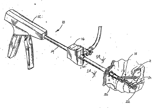
illustrated in Fig. 1 and is designated generally by
re~erence numeral 10. Apparatus 10 basically comprises a
handle portion 12, an elongated endoscopic portion 14
d.imensioned for passage through a cannula assembly 16 and a
~astener applying assembly 18 having a pair o~ cooperating
arms 20 and 22 ~or effectuating application of a two-part
surgical fastener to body tissue 24 within a body cavity 26
o~ a patient.
The pre~erred two-part surgical ~astener is
composed o~ a bioabsorbable polymeric material although both
bioabsorbable and non-bioabsorbable materials can be
utilized. Examples of bioabsorbable material include
homopolymers or copolymers of lactide, glycolide,
, . .. . - .
~7251
polydioxanone, trimethylene carbonate, polyethylene oxide or
other bioabsorbable polymer ~aterials or blends of these
respec~ive copolymers. one preferred material is made of a
copolymer of lactide and glycolide made from approximately
25% m glycolide and 75~ m lactide blended with a homopolymer
of glycolide so the total composition is composed of
approximately 42% glycolide. Other bioabsorbable resinous
materials for constructing such fasteners are disclosed in
u.s. Patent Nos. 4, 523,591 and 4, 744,365 to Kaplan et al.,
both of which are herein incorporated by reference.
Clearly, other bioabsorbable materials can be utilized.
Non-bioabsorbable materials contemplated include any
implantable material such as polyester, polypropylene, or
polyethylene.
Referring now to Figs . 2 and 7, the upper arm 20
of fastener applying assembly 18 has an elongated retainer
supporting portion 28 having opposed proximal and distal
ends 30 and 32. A substantially rectangular channel 34 is
formed within the retainer supporting portion 28 for
maintaining and feeding a plurality of retainers 36 which
make-up half of the two-part surgical fastener which the
apparatus 10 of the subject invention is designed to apply.
The rectangular channel is configured and dimensioned to
support, contain and feed retainers in the longitudinal
direction along the channel. This is accomplished through
the justification of the four outside surfaces 36a, 36b, 36c
and 36d as shown in Figs. 5 and 6. Each of the retainers 36
have spaced apart apertures 38 and 40 structured for engaged
reception of the corresponding pronged legs of the fastener.
A securement portion 42 with a down-turned lip 44 extends
outwardly from the distal end 32 of the retainer supporting
-19-
2:~ ~72~:~
portion 28 of upper arm 20 for stabilizing the distalmost
retainer 36 as well as loca~ing the retainer relative to the
distalmost fastener member. A mounting aperture ~6 i5
provided in the proximal end 30 of retainer supporting
portion 28 Of arm 20 for receiving a pivot pin 48. Insert
grooves 50 and 52 are defined in the proximal end 80 of
retainer supporting portion 28 for cooperating with
corresponding upstanding mounting struts 54 and 56 formed on
the lower driving arm 22.
As shown in Figs. 3 and 5, guide flange 58 extends
from the proximal end 30 of retainer supporting portion 28
for cooperating with a longitudinal guide slot 60 formed in
lower driving arm 22. An aperture 62 is provided in guide
flange 58 for permitting cooperation of the upper arm 20 and
the lower arm 22. This cooperation will be discussed
further hereinbelow. A spring loaded biasing member 66 is
disposed within the rectangular channel 34 of retainer
supporting portion 28 for biasing a plurality of retainers
members 36 toward the distal end 32 of retainer supporting
portion 28. Biasing system 66 is adapted for uniform
plunger-like translation along the longitudinal axis of the
elongated driving arm 20 within channel 34 and operates
through a coiled spring mechanism (shown schematically) to
bias the retainers in the distal direction. An elongated
cover plate 68 is provided for mounting to the retainer
supporting portion 28 of arm 20 adjacent channel 34 ~or
maintaining the retainer 36 and the biasing member 66 in
channel 34.
~ .. , . ~ . . .. . .
21 ~ ~ 2t~ 1
Re~erring to Figs. 3 and 8, the lower driving arm
20 of the surgical fastener applying assembly 18 includes a
body portion 7G having a distal end 72. A ~astener
supporting portion 74 is defined adjacent the distal end 72
of body por~ion 70 and is provided with a substantially
rectangular channel 76 for maintaining and feeding a
plurality o~ fastener members 78 which make~up the second
half of the two-part surgical fastener contemplated for
application by the apparatus lO of the subject invention.
The rectangular channel is configured and dimensioned to
support, contain, and feed subsequent fastener members along
the longitudinal axis of the channel. This is accomplished
through the justification of the four outside surfaces 78a
~side), 78b (bottom), 78c (side), and 78d (distal) of the
fastener members as best shown in Figs. 5 and 6.
Each of the fastener members 78 include two prongs
80 and 82 extending from a backspan 84. Prongs 80 and 82
are adapted for engagement w.ithin the spaced apart aperture
areas 38 ana 40 of retainer 36. A biasing member 86 is
disposed within the proximal end of channel 76 for uniformly
urging the plurality of fastener portions 78 in plunger-like
fashion toward the distal end 72 of body portion 70 and
operates through a known coiled spring mechanism, the
details of which are not shown. An elongated cover member
88 is provided for mounting adjacent channel 76 so as to
maintain fasteners 78 and biasing member 86 within channel
76.
The surgical apparatus lO further comprises a
mechanism for approximating the upper arm 20 toward the
lower arm 22 during surgical procedures. The approximating
mechanism comprises a pair of elongated draw bars 90 and 92
~1~725 ~
whirh are disposed on either side o~ low~r arm 22 a~d which
are operatively connected to the handle portion 12 through
endoscopic portion 14. Draw bar 90 has an elongated body
portion 94 and a distal head portion 96 depending from body
portion 9~ which is provided with an inverted U-shaped notch
98. Similarly, draw bar 92 has an elongated body portion
100 having a distal head portion 102 which depends therefrom
and which is provided with an inverted U-shaped notch 104.
The approximating mechanism further includes a pair of
opposed clearance grooves 106 and 108 which are defined in
the body portion 70 of lower arm 22. Clearance grooves 106
a~d 108 each approximately describe an arc whose center of
rotation is the pivot 48 of upper arm 20. An elongated pin
llo extends through clearance grooves 106 and 108 and
aperture 62 in the guide flange of upper arm 20, and is
engaged in the inverted U-shaped notches 98 and 104 in draw
bars so and 92, respectively. Longitudinal movement of draw
bars 90 and 92 will cause corresponding translation of the
pin 110 within clearance grooves 106 and 108. This movement
causes corresponding approximating movement of the upper arm
20 relative to the lower arm 22.
Another mechanism for effectuating the
approximation of the upper arm 20 toward the lower arm 22 o~
fastener applying assembly 18 is also envisioned which
comprises a flexible draw cable extending operatively from
handle assembly 12, through endoscopic portion 14, to upper
arm 20 (see generally Fig. 50). ~his mechanism will be
discussed in greate.r detail hereinbelow.
With continued re~erence to Fig. 3, the surgical
apparatus lo of the subject invention further includes a
mecbanism for driving at least one of the plurality of
`:
.
2 ~ 7 2 .~ 1
fastener members 78 into engagement with at least one of the
retainer members 36 of the two-part surgical fastener, for
fastening tissue during a surgical procedure. It is
envisioned however, that this mechanism may be configure~ in
such a manner so as to simultaneously drive a predetermined
number of fastener members 78 into engagement with a
predetermined number of retainers 36. The driving mechanism
comprises a linkage assembly including a pair of elongated
camming arms 111 and 112 disposed on either side of the body
portion 70 of lower arm 22. Camming arms 111 and 112 are
operatively connected to the handle portion 12 of the
apparatus 10 through endoscopic portion 14 in a manner which
will be discussed in greater detail hereinbelow. Camming
arm 111 includes an elongated body portion 114 and a head
portion 116 which depends angularly from the elongated body
portion 114. A camming slot 118 is defined in the head
portion 116 for accommodating translation of the camming arm
111 relative to a cam follower 120. More particularly, the
cam follower 120 has a head portion 122 which cooperates
with the cam slot 118, and a tail portion 124 adapted for
linear movement within a transverse clearance tracX 126
formed in side wall 128 of body portion 70.
Similarly, camming arm 112 has an elongated body
portion 130 and a head portion 132 which depends angularly
from the body portion 130. A camming slot 134 is defined in
the head portion 132 for permitting translation of camming
arm 112 relative to a cam follower 136 having a head portion
138 which cooperates with camming slot 134, and a tail
portion 140 adapted for linear movement within a transverse
clearance track 142 formed in side wall 144 of body portion
70. The driving mechanism further comprises a pair of
,
,
1~-
2~2~1
elongate~ pivoting rocker arms 146 and 148. Rocker arm 146
has opposed proximal and distal ends 150 and 152 and is
pivotably connected to the body portion 70 of lower driving
arm 22 by an integral pivot pin 154 which is mountable
within an aperture 156 provided in body portion 70. An
aperture 158 is provided at the proximal end 150 of rocker
arm 146 for engagement with the head portion 122 o~ cam
~ollower 120. This connection, links the rocker arm 146
with the camming arm 111. An outwardly extendinq prong 160
is provided at the distal end 152 of rocker arm 146. Prong
160 is engagable within a receiving aperture 162 formed in a
lift member 164.
As shown in Fig. 3, lift member 164 is provided
with inwardly extending rails 164a which are slidable for up
and down movement within grooves 70a in body portion 70.
The rails 164a and grooves 70a facilitate steady upward and
downward movement for lift member 164 to provide accurate
alignment of fastener member 78 with corresponding retainer
36 as will be described.
As shown in Fig. 4, lift member 164 has a groove
166 formed therein (see also Fig. 11) for receiving and
locating the distalmost fastener member 78 from channel 76
relative to the distalmost retainer. This groove also
retains the distalmost fastener member and prevents
longitudinal and lateral motion during its insertion into
the retainer. Rocker arm 148 has opposed proximal and
distal ends 168 and 170 and is pivotably mounted to body
portion 70 of lower driving arm 22 by an integral pivot pin
172 disposed intermediate proximal and distal ends 168 and
170 thereof. An aperture 174 is provided in the proximal
end 168 of rocker arm 148 for engaging the head portion 138
- .
. ..... .
210~
of cam follower 136 to interconnect rocker arm 148 with
camming arm 112. A p~ong 176 extends outwardly from the
distal end 170 of rocker arm 148 for engagement in a
receiving aper~ure 178 provided in liEt member 164. A
positioning stop 180 extends outwardly from the distal end
72 of body portion 70 for locating the lift member 164 of
the driving mechanism.
In operation, once the fastener applying assembly
18 of the surgical apparatus 10 of the subject invention has
been extended into the body cavity 26 as illustrated in Fig.
1, the upper arm 20 of assembly 18 may be moved into an open
position, best seen in Fig. 4. In this open position, the
elongated push rod 90 of the approximating mechanism is in
its distalmost position resulting in the camming pin 110
being maintained in a distal area of the clearance groove
106. By maintaining the camming pin 110 in this manner, the
upper arm 20 is supported in an upright position whi~h is
desirable to receive tissue between the cooperating arms 20
and 22 of the fastener applying assembly 18. Furthermore,
when in this non-operative tissue receiving position, the
fastener driving mechanism of the apparatus lo is in a
neutral condition wherein the angled head portion 116 of cam
arm 11 is in its distalmost position. Consequently, the cam
~ollower 120 is positioned in the most proximal area of the
cam slot 118 of head portion 116, while at the same time
being disposed in its highest position within the transverse
clearance track 126 ~ormed in body portion 70 of lower arm
22. Thereupon, the distal end 152 of the pivoting rocker
arm 146 is in its lowest position at the distal end 72 of
the lower arm 22. While in this lowest position, the lift
~ ~ member 164, wh.ich is secured to the prong 160 at the distal
....... . .
-2~-
2~ 07~Sl
end 152 of rocker arm 146 is ~upported upo~ the positioning
stop 180 which ext~nds outw~Edly from the distal end 72 of
body portion 70.
Turning to Fig. 5, once tissue has been dispo~ed
between the cooperatiny arms 20 and 22, the upper arm 20 may
be approximated toward the lower arm 22, closing the gap
therebetween, until such time as the aXes of each arm are
substantially parallel to one another thereby retaining the
~issue therebetween. The approximation of arm 20 is
achieved through manipulating the handle portion 12 of the
apparatus 10 in such a manner so as to pull the elongated
draw bar ~0 in a proximal direction causing camming pin 110
to move into a proximal area of the angularly oriented
clearance groove 106. Once arm 20 has been approximated,
the distalmost retainer 36 of the two-part surgical fastener
is ir a position for receiving the distalmost fastener
member 78 of the two-part surgical fastener, as best seen in
Figs. 6-8. More particularly, the backspan 84 of the
distalmost ~astener member 78 is supported and aligned
within groove 166 formed in the lift member 164. At the
same time, the distalmost retainer 36 is secured in a
receiving position by the down-turned lip 44 o~ the
securement portion 42 which is disposed at the distal end 32
of upper arm 20 (see Fig. 7).
As best seen in Fig. lA, the distal portion of
endoscopic portion 14 includes internal sealing means 14a
which maintains the operative site at positive pressure
during the endoscopic or laparoscopic surgical procedure.
The sealing means is formed of a compliant impermeable
material such as closed-cell foam rubber, natural or
synthetic rubber, or a viscous liquid such as silicone
.
~1 .
-21-
grease, for example. The material surrounds the actuating
member~ as shown in Fig. lA within endoscopic tubular
portion 14. Such compliant material forms a gasket seal
around the actuating members while still permitting the
longitudinal movement of the actuating members through the
sealing means with no loss of insufflation pressure past the
sealing means.
Referring now to Figs. 9 11, the handle assembly
12 of the apparatus 10 may be manipulated in a manner which
will be described hereinbelow so as to drive the distalmost
fastener member 78 toward the distalmost retainer 36 of the
two-part surgical fastener. In driving a fastener member,
the angled head portion 116 of cam arm 111 is moved in a
proximal direction, relative to the cam follower 120.
Concomitantly, cam follower 120 translates in a downward
direction within the transverse clearance track 126 formed
in body portion 70. As a consequence of the camming
movement of cam follower 120, the distal end 152 of the
rocker arm 146 is moved upwardly, carrying the lift member
164 off of positioning stop 180, and thereupon urging the
fastener member 78 toward the retainer 36 of the two-part
surgical fastener.
Turning now to Figs. 12 and 13, to drive the
distalmost fastener member 78 into engagement with the
distalmost retainer 36, whereby the two prongs 80 and 82 at
the end of backspan 84 will be interlocked within the spaced
apart aperture areas 38 and 40 o~ the distalmost retainer
36, the camming arm 111 is moved in such a manner so that
the cam follower 120 is positioned in the distalmost area of
cam slot 118, and is moved into its lowest position in the
transver-e track 126 ~ormed in body portion 70.
.
- .
21~7~
Consequently, the distal end 152 of rocker arm 1~6 is
pivoted into its highest position relative to lower drivin~
arm 22, causing lift member 164 to urge the distalmost
fastener member 78 into engagement with the distalmost
retainer 36 of the two-par~ surgical fastener. As the
distalmost fastener member 78 engages the distalmost
retainer 36 it becomes applied to the target tissue. At
this point, the distalmost fastener member 78 will have
essentially exited the rectangular channel 76 and is
essentially free of the grip of channel 76 of body portion
70. During this process, while the lift member 164 is in
the driving position, the body of the lift member withholds
the line of fasteners from moving distally under the force
of biasing member 86 which normally urges the line of
fasteners in the distal direction. As lift member 164
returns to its home position toward positioning stop 180 the
proximal wall 164a of lift member 164 engages the distally
biased distal-most fastener and urges the entire row of
fasteners to move proximally through a short distance. When
the lift member 164 returns to its home position on the
positioning stop 180 by the reverse sequence of the
mechanical operation described, the biasing member 86 in
channel 76 of body portion 70 urges the next-in-line
fastener member 78 into a driving position. The cooperating
arms 20 and 22 of the fastener applying assembly 18 can then
open. Since the distalmost fastener member 78 and the
distalmost retainer 36 are now locked onto the target
tissue, this opening motion will cause the distalmost
retainer 36 to be withdrawn from the upper arm 20, passing
over the down-turned lip 44. At this point the biasing
member 66 in channel 34 of support portion 28 urges the
-2~-
21~72.-)1
next-in-line retain~r 3 6 into position against the
securement portion ~2 with down-turned lip 4~. This
effectively completes the process and the instrument is now
ready for the next application of surgical fast~ners.
Referring now to Fig. 14 an alternative embodiment
of the inventive apparatus is shown. In the description of
this embodimPnt, similar components and elements are
identified by the same numerals as like components which are
identified in the previous embodiment of the apparatus
except that all referen~e numerals are preceded with the
numeral "2". Thus, the embodiment of Fig. 1 illustrates
apparatus 10 whereas in Fig. 14 the numeral is 210.
Referring again to Fig. 14, apparatus 210 includes
handle portion 212, and elongated endoscopic portion 214
dimensioned for passage through a cannula assembly. A
fastener applying assembly 218 is provided at the distal end
of endoscopic portion 214 and includes a pair of cooperating
arms 220 and 222 for effectuating application of a two-part
surgical fastener on tissue within the body cavity of a
patient. The structure and operative principles of the
embodiment shown in Fig. 14 are substantially identical to
those of the previous embodiment discussed hereinabove with
the exceptions specifically described in the description
which follows.
Referring to Fig. 15, retainer supporting portion
228 is modified at the distal end by replacing securement
portion 42 of the previous embodiment with distal wall 242
to receive and guide retainers 236 as best shown in Fig. 17.
The flat inner surface 242a of distal wall 242 as best shown- -
in Fig. 18 provides precise positioning of the distalmost
retainer during advancemant of the retainer 236.
.
--24--
Additionally, the cover plate ~ lncorporates two compliant
fingers 26~a which partially contain the distal-most
retainer 236. After insertion of the fastener and opening
o~ the retainer supportin~ portion 228, these compliant
fingers 268a deflect allowing the withdrawal of the
distalmost retainer. After insertion of fastener 218 into
retainer 236, the retainer moves with the fastener and is
thus released by compliant fingers 268a.
Referring now to Fig. 16, the fastener supporting
portion of the embodiment of Fig. 14 is illustrated. As
noted, this embodiment includes components identical to the
previous embodiment, except that lift member 164 of the
previous embodiment has been replaced by lift member 264
which includes vertical channels 264a configured and
dimensioned to slidably receive correspondingly configured
and dimensioned rails 272a at the distal end 272 of fastener
supporting portion 274. Thus the distalmost fastener 278 is
protected and positively positioned in every significant
coordinate surface for movement in directions toward and
away from the retainer support means 228 of Fig. 15. As can
be seen in Fig. 16 the bottom surface 278b is in surface
contact with the lift member 264, side surfaces 278a and
278c are in contact with the side walls of lift member 264
and the distal surface 278d is in contact with the proximal
wall 264a of lift member 264. When lift member 264 is in
position at the distal end of support 274 a positive support
sur~ace ~or ~astener 278 is provided by the proximal surface
264a of the lift member 264. This precise positioning of
fastener member 278 thus facilitates precise interactive
mating of the fastener members 278 and retainers 236 when
-~5-
21~72~1
the lift member 264 is advanced upwardly toward the retainer
support means 228 as described in the previous embodiment.
Turning to Fig. 17, lift member 264 includes a
groove 266 defined between proximal wall 264a and proximal
lip 264b and dimensioned to maintain the precise orientation
of fastener 278. Additionally, lift member 264 is
configured to include tapered proximal surface 264c which
will initially permit the fasteners to move forward a
slightly greater distance under bias of resilient member 266
during a fastener li~ting process. Thereafter, as lift
member 264 is lowered the gradual taper of proximal surface
264c will initially permit the fasteners to move forward a
slightly greater distance under bias of resilient member
266. As lift member 264 is lowered further, the gradual
taper of proximal surface 264c will contact the fastener
next-in-line and provide a slight proximal movement to the
row of fasteners as the lift member 264 returns to its home
position below the next-in-line fastener. Essentially, the
tapered surface permits greater movement to the fasteners
during the upward and downward translation of lift member
264.
Referring now to Fig. 16 additional features of
the invention are illustrated and include a pair of
upstanding locator extensions 274b which engage and surround
the retainer support portion 228 when the retainer support
portion 228 is closed for firing a fastener. These locator
extensions provide stable positioning and positive location
of the retainer support portion 228 relative to the fastener
support portion 274. In addition, a tissue stop 274c is
pivotally positioned with a torsion spring 274d to bias the
tissue stop 274c toward the upward position as shown in Fig.
.' ' ~ ~ ' ' '. ':
.
-26-
21072~1
17. One e~d of spring 27~d engages a dip on tissue stop
274c and the other free end is fixedly positioned relative
to fastener support 274. When tissue is positioned within
the open jaws of fastener applying assembly 218, tissue stop
274c prevents the tissue of the patient from extending
inwardly to the hinge area of the apparatus, thus preventing
trauma to tissue and unwanted jamming of the instrument,
while providing a limit for location of the tissue. When
the upper jaw 220 of assembly 218 has been closed ~or firing
the apparatus, tissue stop 274c is pivoted downwardly with
upper jaw 220 continuing to prevent tissue damage.
Referring now to Figs. 20-37, wherein like
reference numerals indicate similar structural elements or
components, three distinct embodiments of the handle
assembly 12 of surgical apparatus 10 are illustrated.
Turning initially to Figs. 20-24, a first
embodiment of the handle assembly of the subject invention
is illustrated and is designated generally by reference
numeral 400. Handle assembly 400 comprises barrel portion
402, stationary gripping handle 404, and pivoting actuation
handle 406 which is pivotably mounted to the barrel portion
402 by pivot pin 405. Handle assembly 400 includes two
primary mechanisms for operating the astener applying
apparatus 10 of the subject invention. These include a
first mechanism or e~ectuating the approximation of the
upper jaw 20 relative to the lower jaw 22 o the astener
applying assembly 18, and a second mechanism for
effectuating the driving of the fastener portion into
engagement with the retainer portion of the two-part
surgical fastener. Both o these mechanisms are operated
through manipulation of the pivoting actuation handle 406.
.
-27-
21~72~ 1
More particularly, manipulation of pivoting handle 406
through a first distance will effectuate jaw approximation,
while manipulation of the pivoting handle 406 th~ough a
second further distance will effectuate the driving of the
fastener portion of the two-part surgical fastener into
engagement with the retainer portion thereof.
The first mechanism for effectuating approximatisn
of the jaws includes an approximation cable 408 which
extends from handle assembly 400, through the endoscopic
portion 14 o~ the instrument, to the fastener applying
assembly 18 at the distal end thereof. The proximal end of
cable 408 is fastened to a draw plate 410 which is
operatively engaged to an actuation cam 412. Actuation cam
412 is substantially housed within stationary handle 404 of
handle assembly 400 and is pivotably connected thereto at a
pivot point 414 disposed at the lower end thereof. A
plurality of spaced apart coiled springs 415a, 415b, and
415c are associated with actuation cam 412 for biasing
actuation cam 412 relative to stationary handle 404.
Locking mechanism 416 is provided for interlocking
pivoting handle 406 and actuation cam 412 with respect to
each other. By doing so, th~ jaws of the fastener applying
assembly will be maintained in a closed position. It is in
this closed position that the instrument is intended to be
introduced to the surgical site through the trocar or
cannula device as shown, for example, in Fig. 1. Exemplary
trocar or cannula devices are disclosed in commonly assigned
U.S. Patent No. 4,943,280 to Lander and U.S. Patent No.
4,654,030 to Moll, the contents of which are herein
incorporated by reference. Locking mechanism 416 includes a
catch shelf 418 extending outwardly in a distal direction
:
- 28 -
2~72~3
from actuation cam ~12 and a spring-biased over-centered
latch 420 pivotably associated with actuation handle 406 and
disposed upon a ledge extending rearwardly therefrom.
Turning to Fig. 21, actuation cam 412 defines an
arcuate cam surface 422 adjacent the cable mounting area 424
thereof along which a primary cam follower 426 travels to
effectuate reciprocating movement of approximation cable
408. Cam follower 426 iS formed on the pivoting actuation
handle 406 adjacent pivot point 405. A depression area 428
is defined at a point intermediate the path of cam surface
422 for reception of cam follower 426 at a particular point
in its translation. Specifically, the position of the
depression area 428 corresponds to the position in which the
pivoting handle 406 is in when lock mechanism 416 is in its
horizontal position. As best seen in Fig. 22, pivotable
movement of actuation cam 412 in a counter-clockwise
direction about pivot point 414 will thus be effected by
translation of cam follower 426 along cam surface 422 by
manipulating actuation handle 406 through a first distance.
The second mechanism for effectuating the driving
of the fastener portion of the two-part fastener into
engagement with the retainer portion thereof is shown in
Fig. 20. This mechanism includes a driving cable 430 which
extends from handle assembly 400, through endoscopic portion
14, to the linkage mechanism associated with the fastener
appl~ing camming arms 111 and 112 of the assembly of the
subject invention. A proximal end of driving cable 430 is
mounted in a flange portion 432 of dual cam links 434a and
434b. Dual cam links 434a and 434b are pivotably mounted in
the barrel portion 402 of handle assembly 400 by pivot pins
435a and 435b and define substantially linear cam surfaces
-29-
21~72~1
436a and 436b alon~ which secondary cam followers 438a and
438b travel. Secondary cam followers 43aa and 43sb are
preferably formed integral with actuation cam 412 adjacent
the cable mounting area 424 thereof. Coiled springs 440a
and 440b are provided for biasing cam links 434a and 43~b
relative to barrel portion 402.
As best seen in Fig. 23, movement of cam link 434
will be effected by movement of actuation cam 412 in
response to manipulation of actuation handle 406 which will
cause cam follower 438 to travel along cam surface 436,
urging cam link 434 to pivot about pivot point 435, thereby
drawing drive cable 430 in a proximal direction.
Referring to Fig. 20A, an alternative embodiment
of handle assembly 400 is illustrated which comprises a
ratchet mechanism 415 housed within barrel portion 402 for
controlling the movement of actuation handle 406. Ratchet
mechanism 415 includes a communication beam 415a extending
operatively between actuation cam 412 and cam link 434, a
gear rack 415b associated with cam link 434, and a spring
biased pawl 415c integrated with communication beam 415a for
cooperating with gear rack 145b.
In use, as actuation cam 412 rotates in a counter-
clockwise direction in response to manipulation of actuation
handle 406, communication beam 415 travels proximally within
the bore 415d defined in cam link 434. As communication beam
415 translates, it moves relative to gear rack 415b causing
pawl 415c to sequentially interengage therewith. The
interengagement of pawl 415c with gear rack 415b functions
to maintain the position of actuation handle 406 and
consequently serves to maintain the position of the
-30-
21~7~1
actuation mechanisms housed within the barrel portion 402 of
handle assembly 400.
Turning now to Figs. 24-33, a second embodiment of
the handle assembly of the surgical apparatus of the subject
invention is illustrated and is designated generally by
reference numeral 500. Handle assembly 500 is similar to
handle assembly 400 in that approximation of the upper and
lower jaws of the fastener applying assembly associated
therewith, and driving of the ~astener portion of the two-
part surgical fastener into the retainer portion thereof is
effectuated through manipulation of a pivoting actuation
handle 506 relative to a stationary handle 504. Handle
assembly 500 differs from handle assembly 400 however, in
that movement of the actuation cam 512 housed within
stationary handle 504 is transmitted to the approximation
cable 508 and driving cable 5~0 by a gear assembly 540
housed within the barrel portion 502 of handle ass~mbly 500.
The movement of actuation cam 512 through manipulation of
actuation handle 506 is effected by the translation of a cam
follower 526 along an arcuate cam path 522 defined on the
proximal surface of actuation cam 512. Unlike the actuation
cam 412 of handle assembly 400, actuation cam 512 of the
present embodiment of the handle assembly pivots in a
clockwise direction about pivot point 514 upon manipulation
of actuation handle 506.
As best seen in Fig. 25, gear assembly 540
comprises a slide plate 542 having a proximal engaging
flange 544 dimensioned and configured for engagement within
a corresponding mounting port 546 defined in actuation cam
512. Slide plate 542 defines a longitudinal slot 545 for
accommodating a transverse post 548 relative to which slide
2.1~2~1
plate 542 t~anslates upon manipulation of actuation handle
506. Gear assembly 590 further comprises a cable crank 550
mounted for pivotal movement about post 548, and having a
cable engaging tail 552 for mounting the proximal end of
approximation cable 408. Cable crank 550 further includes a
forked reception area 554 for receiving a cam pin 556 which
depends from slide plate 542. Thus, longitudinal
translation of slide plate 542 in a distal direction in
response to pivotal movement of actuation cam 512 will cause
the depending cam pin 556 to urge cam crank 550 to rotate in
a counter-clockwise direction about post 548 from the
position of Fig. 26 to the position shown in Fig. 29,
thereby causing approximation cable 508 to be drawn in a
generally proximal direction for effectuating closure of the
jaws of ~astener applying assembly of the instrument.
Referring to Fig. 24 in conjunction with Figs. 27
and 28, gear assembly 540 further comprises a pinion gear
560 having an annular tooth portion 562 and a tail portion
564 for mounting the proximal end of driving cable 530.
Pinion gear 560 is also mounted for rotation about post 548.
A gear rack 566 is mounted on slide plate 542 by pins 565a
and 565b and moves therewith to interact with pinion gear
560 to effectuate the rotation thereof. Thus, distal
movement of slide plate 542 in response to movement of
actuation cam 512 will urge gear rack 566 to move relative
to pinion gear 560 from the position of Fig. 27 through the
position shown in Fig. 30, to the position of Fig. 33,
causing the counter-clockwise rotation of pinion gear 560
- and consequently drawing driving cable 530 in a generally
proximal direction to effectuate driving of the fastener
portion of two-part surgical fastener into engagement with
:
:
:
. . .'. ' , ~,
-32-
the retainer portion thereof. A coiled spring 570 is
provided for biasing actuation cam 512 relative to the rear
wall of ~arrel portion 502 to effectuate the return ~hereof
following an actuation sequence. A substantially
cylindrical sleeve 572 is provided in barrel portion 502 for
mounting the gear assembly 540 and for inhibiting
entanglement of the motion transmitting cables 508 and 530
as the gear assembly 540 is actuated (see Fig. 24).
In use, gradual manipulation of actuation handle
506 through a first distance from the position of Fig. 24 to
that of Fig. 28 will cause distal movement of slide plate
542 through a first distance causing the rotation of cable
crank 550 through approximately a 45 sector of rotation to
draw approximation cable 408 proximally, while manipulation
of actuation handle 506 through a second distance from the
position of Fig. 28 to that of Fig. 31 will cause distal
movement of slide plate 542 through a second further
distance, causing continued counter-clockwise rotation of
pinion gear 560 through approximately a 45 sector of
rotation, as shown in Fig. 33, to draw driving cable 430
proximally.
A third embodiment o~ the handle assembly of the
surgical apparatus lo of the subject invention is
illustrated in Figs. 34-37 and is designated generally by
reference numeral 600. Handle assembly 600 is substantially
di~ferent than either of the handles discussed hereinabove
~i.e. handle assembly 400 and handle assembly 500) in that
handle assembly 600 has separate actuation handles for
effectuating the movement of each of the transmission
cables. In particular, handle assembly 600 comprises barrel
portion 602, stationary handle 604 depending from barrel
:
. , .
`:
-33
21~72~1
portion 602, actuation handle 606 pivotably connected to
barrel portion 602 at a pivot point 605 for effectuating
reciprocating movem~nt of approximation cable 608, and an
articulating handle 625 pivotably connected to the barrel
portion 602 of handle assembly 600 for effectuating
reciprocating movement of driving cable 63 0 .
Referring to Fig. 34, the articulating handle 625
of handle assembly 600 includes a main handle member 680
connected pivotably to barrel portion 602 by pivot pins 682a
and 682b. A pair of handle links 684a and 684b are
pivotably connected to main handle 680 by respective pivot
pins 685a and 685b extending through corresponding ports
686a and 686b. Transverse cable connector pin 688 is
pivotably connected to handle links 684a and 68~b through
opposed pins 690a and 690b which extend through
corresponding ports 692a and 69~b. Cable COnneGtOr pin 688
is adapted to mountingly receive the proximal end of
approximation cable 608 to effect the drawing thereof.
Transverse cable connector pin 688 is mounted for movement
within opposed linear tracks 694 defined in the side walls
of barrel portion 602 of handle assembly 600. Manipulation
of main handle 680 toward barrel portion 602, as illustrated
in Fig. 36, will cause handle links 684a and 684b to urge
cable connector pin 688 proximally, drawing therewith
approximation cable 608 to cause the opposed jaws of the
fastener applying assembly to close upon one another.
Similar to handle assembly 400, handle assembly
600 shown in Fig. 34 includes an actuation cam 612 housed
substantially within stationary handle 604 and pivotably
movable in a counter-clockwise direction in response to
translation of a cam ~ollower 626 along an angled cam path
~: ~
.
.
--3a,--
2~072~
622 defined on the forward ~urface of actuation cam 612.
The proximal end of driving cable 630 is mount~d to a cable
fastener plate 645, the proximal end of which is configured
for engagement in the mounting portion 624 of actuation cam
~12. Thus, manipulation of actuation handle 606 from the
position of Fig. 36 to that of Fig. 37 will cause counter-
clockwise movement of actuation cam 612, drawing driving
cable 630 in a proximal direction as fastener plate 6~5 is
pulled rearwardly to drive the fastener portion of the two-
part fastener into engagement with the retainer portion
thereof.
Referring now to Fig. 38, an alternative
embodiment of a surgical apparatus constructed in accordance
with the subject invention is illustrated and is designated
generally by reference numeral 700. Surgical apparatus 700
is similar in most respects to the apparatus of the previous
embodiments, but incorporates additional features which
function to increase the operational range of the
instrument. More specifically, surgical apparatus 70Q
incorporates a fastener applying assembly adapted for
articulated or pivoted movement through an angular sector of
rotation relative to a longitudinal axis defined by the
endoscopic portion of the instrument. Additionally, a
detent mechanism is also provided for positively
establishing the articulated positions of the fastener
applying assembly with respect to the longitudinal axis
defined by the endoscopic portion of the instrument. A
frame of reference is provided in Fig. 38 which defines the
longitudinal axis of endoscopic portion 704 as the x-axis
and the axis about which the fastener applying assembly 706
rotates as the z-axis.
.
., . , ~ . . . .
i, ~, .
`
2~ 0~251
The combination of th~ above-listed features
provides extremely precise positioning of a two-p~rt
surgical ~astener at numerous angular orientations to
facilitate application thereo~ at a precise location. These
features, combined with the features described in connection
with the previous embodiments of the subject invention,
individually or in combination, provide a surgical apparatus
which represents a significant improvement over the highly
effective embodiments described previously.
Surgical apparatus 700 is illustrated in Fig. 38
and comprises a handle portion 702 and an endoscopic section
704 having at the distal end portion thereof a fastener
applying assembly 706 which includes a fastener support arm
708 on which is mounted a retainer support arm 710.
Generally, the handle portion 702 supports the actuating
components described hereinabove in connection with the
previous embodiments of the invention. Furthermore, it may
be stated that the ~astener support arm 708 is pivotally
mounted to the distal end of the endoscopic portion 704 and
such pivotal movement thereof will result in similar
movement of the retainer support arm 710 since it is
directly associated therew-th.
The mechanism for effectuating articulated pivotal
movement of the fastener applying assembly of surgical
apparatus 700 between a plurality of selected angled
positions with respect to the longitudinal axis of the
endoscopic section 704 is illustrated in Figs. 39-43 and is
specifically controlled through manipulation of a knurled
collar 725 disposed adjacent the barrel of handle portion
702. The preferred dimensions of components such as the
llnks and the rods which form the mechanism have been
.
.
-36-
21~7251
selected to effect pivotal movements of the fastener
applying assembly from about positive 45 ! to about oo, then
to about negative 45O. However, ~he relevant dimensions and
mechanical advantages of these components may be selected to
provide other alternative angular orientations for the
fastener applying assembly. For example, in an alternative
preferred embodiment of the invention, the components may be
configured to provide angular orientations of 0, 32.5 and
65 ~or the fastener applying assembly as will be described
in further detail hereinbelow.
Referring to Fig. 39, collar 725 is structured and
dimensioned to contain a series of plates including an upper
plate 802, a lower plate 804 and a central centering plat~e
806 having a distally extending leg 808 and a proximally
extending leg 810. Lower plate 804 includes a cut-out 812
which is dimensioned and configured to receive centering
plate 806 as shown in Fig. 40 with legs 808 and 810
respectively surrounded by coil springs 814 and 816. When
the plates are assembled and positioned within axial opening
724 in collar 725 centering springs 814 and 816 serve to
maintain the centered position of centering plate 806 within
the cut-out 812 of lower plate 804. The assembled plates
are then positioned within a mechanism housing defined by
upper housing member 864 and lower housing member 865
adapted to interconnect with endoscopic portion 704.
Lower plate 804 contains cylindrical apertures
818, 820, and 822 in which are positioned corresponding
locator balls 824, 826, and 828. Depending upon the
position o~ lower plate 804 with respect to lower housing
865, pin 830 is biased upwardly by spring 832 to position
- 37 -
21~2~ 1
th~ balls within the respective conical aperture 834, 836,
and 838 to locate and fix the position of upper plate ao~.
Pin 840 extends through aperture 8~2 in collar 725
and through aperture 845 in upper plate 802 as well as
through aperture 8~7 in central plate 806 to key these
components together for common distal and proximal movement.
Proximal link 844 is pivotal about pin 846 which extends
through aperture 848 in link 844, aperture 867 in upper
housing 864, and aperture 849 in lower housing 86S. Link
844 contains slot 850 for slidable reception of pin 852.
Pin 852 is longitudinally slidable between a distal position
and a proximal position within slot 866 in upper housing
864, and also extends through aperture 804d in central plate
804. Similarly, distal link 854 is pivotal about pin 856
which extends through aperture 858 and contains slot 860 for
slidable reception of pin 862. Pin 862 is longitudinally
slidable between a proximal position and a distal position
in slot 869 in upper housing 864, and also extends through
aperture 804c in central plate 804.
A detent spring 863 which contains three arcuate
relief sections including distal arcuate detent relief 866,
proximal detent relief 864, and medial U-shaped detent
relief 868 for respective engaged resilient reception of
proximal slidable pin 852. Links 844 and 854 respectively
receive the upturned ends 870p and 872p of drive rods 870
and 872 respectively, each of which are respectively
arranged at their distal ends 870d and 872d to engage wall
portions 821 and 823 defined in the fastener support arm of
the fastener applying assembly to effect articulated
movement thereof as parallel rods 870 and 872 are moved
~ . .. . . . . ~ .
-3~-
2~7251
re~iprocatingly in response to manipulation o~ collar 725
(see Figs. 43-45).
In operation, the initial translation of collar
725 will cause it to advance from the distalmost position
thereof, corresponding to the fastener applying assembly
disposed a~ oo relative to the lo~gitudinal axis of the
endoscopic section, i.e. in line with the section 70~ as
shown in Fig. 48. In this position, pin 852 is engagably
nestled within distal spring detent 866 as shown in Fig. 40
while proximal link 844 and distal link 854 are positioned
as shown. The engaged position of rod 852 in spring detent
866 provides a first detent to retain push rods 870 and 872
from movement, thereby securing the 0 position of the
fastener applying assembly 706. In addition, as shown in
Fig. 40, locator ball 828 is positioned within conically
shaped indentation 834 in upper plate 802 to provide a
second detent mechanism to restrain the movement of push
rods 870 and 872 by outer plate 802 against proximal and
distal movements. Thus, the 0~ position of assembly 706 is
established and fixed by a dual detent system.
Referring now to Figs. 40-45, the mechanical
movements required to produce articulated movement of the
fastener applying assembly 706 are effectuated by
manipulating collar 725 so as to cause proximal advancement
thereof such that outer plate 802 and centering plate 806
move proximally through common connector pin 840. This
proximal movement causes coil spring 816 to engage walls
812a and 812b of lower plate 804 until the spring is
sufficiently compressed and proximal leg 810 moves through a
distance "A" shown in Fig. 40. At this point, leg 810
engages wall 804a of lower plate 804 such that continued
. . ~ .
, ,
- ~9 -
21 07~1
proximal advancement of the collar 725 causes corresponding
movement of lower plate 804. Prior to such engagement,
limited movement of upper plate 802 has taken place to begin
camming ball 828 out of conical indentation 834 as shown in
Fig. 53.
The effect of moving ball 828 is to depress the
ball and pin 830 against spring 832 causing upper plate 802,
intermediate plate 806, and lower plate 80~ to move
proximally together until pin 830 engages central ball 836.
This movement results in proximal movement of pin 852 to the
central detent 868 of spring 8~3 as shown in Fig. 41. In
this Fig., the distal link 854 has moved counter-clockwise
and the proximal link 848 has moved clockwise. The
rotational movement of proximal link 848 is due to the
constraint on pin 852 to slide in slot 866 in upper housing
864 whereas pin 862 associated with proximal link 854 is
constrained to move longitudinally within slot 868 in upper
housing 864. Thus, the respective rotational movement of
links 848 and 854 as described, in turn, result in proximal
movement of the bent proximal end 872p of push rod 872 which
is slidably positioned in the upper portion 861 of slot 860
in link 854 and the distal movement of bent proximal end
870p of push rod 870 which is slidably positioned in lower
slot 845 of proximal link 844. The result of the pivotal
rotation of the links 848 and 854 thus causes the distal
ends 870d and 872d of push rods 870 and 872 to move
proximally and distally, respectively, causing the assembly
706 to pivot to the 32.5~ position shown in Fig. 44.
As the components translate to effect articulated
pivotal movement o~ assembly 706, push rod 870 is slidably
maintained within elongated slot 815 in the upper and lower
~ '
-40~
2~0~25:~
housings 86~ and ~65 and push rod ~72 is slidably maintained
within elongated slot 817 in the upper and lower housings
864 and 865. The lower half portions of these slots 815 and
817 are seen clearly in Fig. 39 in the lower housing 865.
The respective working end portions of push rods 870 and 872
engage suitably configured wall portions 821 and 823 of the
fastener support arm as shown in Figs. 4~-45 to effect the
desired movement.
After the pivotal movement of assembly 706 has
been completed, and the desired position established, collar
725 may be released and this action will relieve the
pressure of coil spring 816 to permit the central centering
pla~e 806 to assume the neutral central position within
aperture 812 of lower plate 804 under tne natural resilient
action of spring 816.
Referring now to Fig. 42, the movement of the
components to effect articulated pivotal movement of the
fastener applying assembly 706 from the 32.5~ position of
Fig. 44 to the 65 position shown in Fig. 45 will now be
described. This movement is produced by continued manual
proximal movement of collar 725 to effect corresponding
continued proximal movement of centering plate 806 and lower
plate 804 in the same manner as described to effect 32.5~ of
movement o~ assembly 706.
Continued proximal movement o~ collar 722 will
cause collar spring 816 to become compressed, as described
above, until collar spring 816 again engages shoulders 812a
and 812b. Once the proximal end of leg 810 of centering
plate 806 engages the proximal wall portion 804a of lower
plate 804 the proximal movement of collar 722 will
terminate.
:
--41--
2 1 0 7 2 j 1
During the initial movement described hereinabove,
the camming action between central csnical aperture 836 in
upper pl~te 802 begins depressing central ball 826 ayainst
spring 832 to begin releasiny the locking engagement
therebetween such that at approximately the point when the
central centering plate becomes keyed to the lower plate,
the ball 826 has been withdrawn from conical indentation
836, thus permitting movement of plates 802, 806, and 804.
At this point pin 832 is positioned beneath distal ball 824
permitting the ball to be received into distal aperture 818
of upper plate 802. With this movement of the upper plate
802 and lower plate 804 in the proximal direction, pin 862,
which is slidably received within the lower portion of slot
861 of link 854, and which extends through aperture 804c,
causes continued clockwise rotation of distal link 854 about
pivot pin 856 to the position shown in Fig. 42, causing
continued proximal movement of push rod 872 within slot 817.
Correspondingly, proximal link 844 is constrained to rotate
further counter-clockwise causing continued distal movement
of push rod 870 within slot 815. This movement results in
further articulated movement of the fastener applying
assembly 706 to the 65 position shown in Fig. 45, in a
manner similar to that described previously.
In the position of the components shown in Fig.
42, assembly 706 is locked in the 65 position by the bias
of spring 832 against pin 830 which locks ball 824 within
distal conical aperture 818 in upper plate 804. Further
locking action is obtained by the resilient force of
proximal detent relief 864 of spring 863 against pin 852
slidably positioned in slot 845 of proximal link 844. When
the desired position of assembly 706 has been aclieved
.
,~ ~
--42--
2~7251
release of collar 725 will permit central centering plate
~06 to return to its central position within aperture 812 of
lower plate 804, thereby relieving the stress on coil spring
816.
Once the jaws are articulated to either of the
32.5 or 65 angular orientations, reversal of the motion to
return assembly 706 toward the 0 position is simply
obtained by reversal of the movements described hereinabove.
In particular, collar 725 is manually returned toward its
original distal position causing the movement of the
components as previously described to be reversed.
Ultimately, when collar 725 is moved to the distalmost
position, all internal components return to the relative
positions shown in Fig. 41 and fastener applying assembly
706 returns to the oo angular position.
As illustrated in Fig. 38, collar 725 is also
adapted and configured to effectuate rotation of endoscopic
portion 704 about the longitudinal axis thereof relative to
the handle assembly 702 of surgical instrument 700. Axial
rotation of endoscopic portion 704 will further increase the
operational range of the fastener applying assembly 706
during a surgical procedure.
As noted hereinabove, in a preferred embodiment of
the subject invention, the articulation mechanism
illustrated in Figs. 39-43 is configured to articulate the
fastener applying assembly 706 within a 904 sector of
rotation. More particularly, the structural elements of the
articulation mechanism described hereinabove may be
configured to effectuate articulation of the fastener
applying assembly 706 to about 45 and about -45O with
respect to the longitudinal axis defined by endoscopic
. :".: , '
.
. .
:
--a, 3_
21072~1
portion 704 (see Fig. 38). In operation, manipulation of
collar 725 from the position illustrated in Fig. 41 to that
which is shown in Fig. 42 will effect articulation of
fastener applying assembly 706 from a 0 orientation to
about a ~5 orientation with respect to the longitudinal
a~is of endoscopic portion 704 (see Fig. 44A). Conversely,
moving collar 725 from the position illustrated in Fig. 41
to that which is shown in Fig. 40 will ef~ect articulation
of fastener applying assembly 706 from the 0 orientation,
in axial alignment with the longitudinal axis of endoscopic
portion 704, to about a
-45~ orientation with respect to the longitudinal axis
defined by endoscopic portion 704 (see Fig. 44B).
An alternative mechanism for effectuating gradual
pivoted articulation of the fastener applying assembly 706
of surgical apparatus 700 within an angular seGtor of
rotation is illustrated in Figs. 46-50. The mechanism is
configured for remote manipulation by the user and comprises
a threaded nose piece 900 which is preferably associated
with the barrel of handle assembly 702 and which defines a
helical thread 905 configured for facilitating axial
advancement of actuation collar 902 through provision of a
pair of diametrically opposed thread following pins 904 and
906 which are dimensioned for travel within thread 905. An
annular race 908 is defined within the axial bore 910 of
actuation collar 902 for accommodating annular mounting ring
912. Mounting ring 912 has a peripheral flange 915
dimensioned ~or seated engagement in race 908. A pair of
diametrically opposed slots 914 and 916 are provided on the
inner circumferential surface 917 of mounting ring 912 and
are dimensioned ~or engaging corresponding ridges 918 and
.
~.. ~.. : .. .....
~072~1
920 formed o~ the outer circumferential sur~ace 919 o~ the
distal end of nose piece 900 to fix the angular orientation
of ring 912 with respect to nose piece soo, ~hile permitting
rotation of collar 902 about a longitudinal axis defined by
endoscopic portion 704 of the apparatus. A mounting
aperture 922 is formed in mounting ring 912 extending
radially through the peripheral flange area 915 thereof ~or
reception of an upturned engaging end portion 924 of an
elongated actuation rod 930. Actuation rod 930 extends at
least partially through the endoscopic portion o~ surgical
apparatus 700 to operatively associate with an articulation
cable assembly which will be discussed in detail
hereinbelow. Finally, an annular cover plate 932 is adapted
to be fastened to the distal surface 934 of actuation collar
902 by a plurality of fasteners 935 to maintain the mounting
ring 912 within the annular race 908.
Turning now to Fig. 47, a distal end portion 936
of actuation rod 930 is terminated in a cable coupling
member 938 which is fastened to a looped articulation cable
940. Articulation cable 940 defines a leading portion 942
and a trailing portion g44. The leading portior. 942 is
operatively mounted to a distal crank member 946 through
reception of an integral lock ball 948 within an engagement
port g50. Similarly, the trailing portion 944 of
articulation cable 940 is operatively mounted to a proximal
crank member 952 through reception o~ an integral lock ball
954 within a corresponding engagement port 956. Proximal
crank member 952 is rotatably mounted upon a transverse post
958 which is secured intermediate the endoscopic portion of
surgical apparatus 700. Distal crank member 946 is also
rotatably mounted upon a transverse post 960 which is
':
,
:
.
--a,5--
2~ 072~1
maintained in the distal end 962 of the endoscopic portion
704 of surgical apparatus 700, as best seen in Fig. 48.
Referring to Fiys. 48-50, distal crank memher 946
is triple-tiered in configuration and includes upper tier
962 Eor accommodating the leading portion 942 of
articulation cable 940, medial tier 964 defining a
passageway for accommodating driving cable 430, and lower
tier 966 defining a passageway for accommodating
approximation cable 408. Parallel mounting pins 968 and 970
extend through the three-tiered structure of distal crank
946 and permit relative rotation of the upper tier 962
relative to the remaining tiers thereof in response to
reciprocated movement of articulation cable 940. A
transverse interconnection pin 972 extends upwardly from the
upper tier 962 of distal crank 946, through an intermediate
plate 974 which defines an arcuate guide track 975 for pin
972 (see Fig. 51), and into an aperture 976 formed in the
proximal tail 978 of the fastener applying assembly 706 of
surgical apparatus 700 (see Fiq. 53). The arcuate path
defined by guide track 975 defines the angular sector of
rotation through which fastener applying assembly 706
travels during articulation.
During a surgical procedure, rotational
manipulation of actuation collar 902 by the. user will result
in gradual longitudinal translation of actuation rod 930
with respect to endoscopic portion 704, as illustrated in
Figs. 47 and 48. As actuation rod 930 advances in a distal
direction, the leading portion 942 o~ articulation cable 940
is gradually urged in a counter-clockwise direction.
Conversely, proximal retreat of actuation rod 930 will
result in olockwise rotation of articulation cable 940.
: : ;
, .
~46-
21Q~2~1
Referring to Fiys. 51 and 51A in conjunction with
Fig. 49, a frame of reference is prcvided similar to that of
Fig. 38, to define the longitudinal axis of endoscopic
portion 704 as the x-axis. Thus, rotation of the upper tier
962 of distal crank 9~6 in response to movement of
articulation cable 940 will cause interconnection pin 972 to
progressively steer the fastener applying assembly 706 of
surgical apparatus 700 through an angular sector of rotation
about the y-axis.
Turning now to Figs 52-54, there is illustrated
the operational sequence of the fastener applying assembly
706 of surgical apparatus 700. Prior to introducing the
apparatus into the surgical site through a trocar or cannula
device, the upper jaw 708 of fastener applying assembly 706
is approximated from the open position of Fig. 52 to the
closed position shown in Fig. 53. As seen in Fig. 52, the
upper jaw 708 of fastener applying assembly 706 is normally
biased into the open position by a looped torsion spring 723
positioned about jaw pivot pin 727. The distal end of
approximation cable 408 is provided with an integral lock
ball 729 engaged within a corresponding reception port 731
formed in upper jaw 708.
As shown in Fig. 50, to effect approximation of
the jaws, the line of action of cable 408 is transferred
from a longitudinal direction to a direction perpendicular
to the axis of the endoscopic portion 704 by a cylindrical
pulley 733 mounted within the lower jaw 710 of fastener
applying assembly 706. Approximation of the jaws can be
achieved, for example, by drawing cable 408 proximally
through manipulation of actuation handle 406 from the fully
open position of Fig. 20 to the partially closed position
-~7-
21~72~1
shown in Fig. 22. Subsequently, actuation handle may be
locked in the partially closed position by latch member ~20.
After the jaws have been approximated and the
instrument has been introduced to the operative site, the
surgeon may release and lock out of place the spring-biased
over-centered latch ~ 2 0 of locking mechanism 416 to permit
the jaws of fastener applying assembly 706 to move to their
normally open position of Fig. 52. At such a time,
actuation handle 406 is once again in the position shown in
Fig. 20. With the jaws in their open position, the surgeon
may position them relative to the tissue to be ~astened. As
the target tissue is oriented between the jaws of the
fastener applying assembly 706, tissue stop 774 serves to
inhibit the tissue from becoming entrapped, thus limiting
the possibility of trauma.
once the target tissue has been properly oriented
between the jaws of fastener applying assembly 706, the
surgeon may manipulate actuation handle 406 to approximate
the jaws. At such time, the surgeon may operate one of the
articulation mechanism discussed hereinabove to position the
fastener applying assembly 706 in any angular orientation
within the sector of rotation illustrated in Fig. 51 so as
to increase the operational range of the instrument.
Thereafter, further compression of actuation handle 406 to
the fully actuated position shown in Fig. 23 will draw drive
cable 430 proximally to effectuate engagement of the
fastener portion of the two-part surgical fastener with the
retainer portion thereof.
Turning to Fig. 54, the proximal end of drive
cable 430 is terminated in a transverse link drawing pin 735
configured for translation within lateral guide slots (i.e.
;~ .
-48-
21072~
guide slot 737) which are de~ined in the lower jaw 710 of
fastener applying assembly 706. Draw pin 735 is engaged to
the right and left camming arms (i.e. arm 739) o~ the
driving mechanism of fastener applying assembly 706. Thus,
proximal tr~nslation o~ drive cable 430 will cause draw pin
735 to pull the camming arms proximally. As discussed
previously with respect to other embodiments of the subject
invention, the camming arms define angled cam slots at the
distal ends such as cam slot 7~3 in camming arm 739 for
effectuating translation of a cam follower 745 within a
transverse track 747 defined in lower jaw 710. Downward
translation of cam follower 745 in response to proximal
movement of draw pin 735 from the distal-most position shown
in Fig. 53 to the proximal-most position shown in Fig. 54
will effectuate counter-clockwise rotation of pivoting
rocker arms (i.e. rocker arm 746) to urge the fastener
portion of the two-part surgical fastener into engagement
with the retainer portion thereof. Once the instrument has
been fired, and actuation handle 406 has been released, a
coiled biasing spring 747 which is associated with the lower
jaw 710 of fastener applying assembly 706 serves to return
the camming arms of the fastener driving mechanism to their
distalmost positions, carrying therewith draw pin 735 and
drive cable 430. At this point, the surgical apparatus of
the subject invention is prepared for a subsequent fastener
applying procedure.
To the extent not already indicated, it also will
be understood by those of ordinary skill in the art to which
the subject invention appertains that any one of the various
specific embodiments herein described and illustrated may be
.
:
'
.
.
" '
--49--
21072~1
furth~r modified to incorporate features shown in other of
the specific embodiments.
Although the andoscopic surgical instrument of the
subject invention has been described and shown with respect
to a preferred embodiment, it would be apparent to one of
ordinary sXill in the art that changes and modifications may
be made thereto without departing from the spirit or ~cope
of the invention as defined by the appended claims.
,.
. ~ , ~ ,
.
.: ' .