Note: Descriptions are shown in the official language in which they were submitted.
.
W092/17288 PCT/US92/02693
21~74a8
` 8Y8TE2~ FOR FI.EXIBLY 80RTING PA}-TICLE~
The invention was made with government support under
~ grant number 5 R01-GM38645 from the National Institute of
`i 5 General Medical Sciences.
.
BACRGROIJ27D AND BIJMMARY OF THE INVEN'rION
,~,
This invention relates to a system for investigating
particles, and in particular to such a system wherein sorted
particles are selected at a yield/purity ratio at very high
signal processing rates.
.~J
Systems for sorting minute particles in a fluid may be
referred to as flow cytometer sorting systems. These systems
are used in the medical research and diagnostic fields for
the rapid analysis and processing of biological cells.
Systems for sorting particles suspended in a liquid
according to certain characteristics are discussed in U.S.
Pat. No. 3,393,606, 4,063,284 and 4,487,320. Specifically,
in these prior art systems optical measurements of
characteristics of each particle of a group of particles are
made while the particles are suspended in a liquid. In one
such system, a flow cytometer cell sorter analyzes cells or
particles in suspension which are labeled with a fluorescent
marker and are carried single file in a fast-moving liquid
stream sequentially through a tightly focused laser beam
whose wavelength is adjusted to illuminate the fluorescent
dye (Bonner, W.A., Hulett, H.R., Sweet, R.G., and
Herzenberg, L.A., Fluorescence Activated Cell Sorting, Rev.
Sci. Instrum. 43:3 404, 1972). The fluorescence produced
during the laser beam crossing is collected by an optical
system and projected through spectral filters onto
photodetectors. These detectors convert the fluorescence to
electrical pulses whose amplitudes depend on the total light
reaching the detectors. Particles having predetermined
characteristics are recognized by their distinctive
: ' .
:
:
, .,,~.. . .,.~ . ,, ~ ..... ., .. .,, . , .. . , ,. , . , .. , ,.. , .,, . , - - . -
... , . .... ,, ,, ~, , ,, " ,", ", ,, " " , ~ , ,
~WO92/17288 PCT/US92/02693
~,~Q~ 2
fluorescence. After measurements of the characteristics,
each particle flows i~ a liquid jet stream until the
particle reaches a point where the jet breaks into discrete
droplets. At this point, an electric charge is induced on
each droplet containing a particle to be sorted and the
charged and uncharged droplets are then sorted
electrostatically into appropriate recovery vessels.
, .
Previously proposed methods of separating particles have
also included separation on the basis of electronically
measured cell volume by charging cells according to a sensed
volume and detecting the charged cells in an electrostatic
field for separation into collection vessels. (Fulwyler,
M.J., Electronic Separation of Biological Cells by Volume,
~ 15 Science 150: 910, 1965). A system has also been proposed
¦ for quantitative analysis and sorting of particles based on
multiple parameters to increase the ability to differentiate
.~ among cell types by measuring the differences between
3 multiple parameters of the cells (Steinkamp, et al., A New
Multiparameter Separator for Microscopic Particles and
Biological Cells, Rev. Sci. Instrum., Vol. 44, No. 9, 1301
(1973). In this system, cells stained with fluorescent dyes
in liquid suspension enter a flow chamber where electrical
and optical sensors measure cell volume, single and two
~25 color fluorescence and light scatter to produce electrical
isignals. A processing signal unit processes the electrical
signals according to preselected parameters and electrically
charges droplets containing the desired cells. The typical
rate at which cells are sorted in this system is a few
hundred cells/sec.
A number of proposals have been described for multiple
parameters, increasing processing speeds and accuracy of
flow cytometer cell sorters. For example, systems have been
proposed for electronics modularization to process as many
as eight input parameters for sorting cells (Hiebert, R.D.,
Jett, J.H., and Salzman, G.C., Modular Electronics for Flow
.~ .
~- WO92/17288 2 1 0 7 ~ i 8 PCT/US92/0269~
. j
Cytometry and Sorting: the Lacel System, Cytometry, 1:337,
1980); a system operating at rates of 15,000-25,000
cells/sec by increasing the pressure in the jet stream to
increase droplet production frequency (Peters, D.,
~' 5 ~ranscomb, E., Dean, P., Merrill, R., Pinkel, D., Van Dilla
M., and Gray, J.W., The LLNL High-Speed Sorter: Design
Features, operational Characteristics, and Biological
Utility. Cytometry 6:290, 1985; Peters, D., Dean, P., and
3 Merrill, J.T., Multi-Parameter, Computer Controlled
Operation of a FACS II Cell Sorter, Cytometry 2:350, 1982).
1 Examples of systems for increasing accuracy are: a system to
J, assure proper timing (Martin, J.C., McLaughlin, S.R., and
Hiebert, R.D., A Real Time Delay Monitor for Flow-System
Cell Sorters, J. Histochem. and Cytochem., 27(1): 277,
1979), sort timing a system for increasing droplet
breakoff stability (Stovel, R.T., The Influence of Particles
on Jet Breakoff, J. Histochem. and Cytochem. 25(7): 813,
1977; Auer, R.E., Method and Apparatus for Detecting Change
in the Breakoff Point in a Droplet Generation System
(analysis of blood cells), U.S. Patent 4,487,320, 1984;
Auer, R.E., Method and Apparatus for Detecting Change in the
Breakoff Point in a Droplet Generation System (radiation
sensing means), U.S. Patent 4,691,829, 1987); a system
3 describing individual cell sorting (Stovel, R.T., Individual
Cell Sorting, J. Histochem. and Cytochem. 27(1): 284, 1979);
a system correlating multiparameter data for each cell
(Parson, J.D., Hiebert, R.D., and Martin, J.C., Active
Analog Pipeline Delays for High Signal Rates in Multistation
~ Flow Cytometers, Cytometry 64:388, 1985); and a system for
¦ 30 parallel processing a signal from a large number of
detectors (van den Engh, G., and Stokdijk, W., Parallel
Processing Data Acquisition System for Multilaser Flow
Cytometry and Cell Sorting, Cytometry 10: 282, 1989).
~ Further, systems for improving the processing of electronics
;~ 35 of flow cytometry applications with computers have baen
proposed (Steinkamp, J.A., Fulwyler, M.J., Coutler, J.R.,
Hiebert, R.D., Horney, J.L., and Mullaney, P.F., A New
,
.
` WO92/17288 PCT/US92/02693
~ 4~
Multiparameter Separator for Microscopic Particles and
Biological Cells, Rev. Sci. Instrum. 44: 1301, 1973;
Steinkamp, J.A., and Hiebert, R.D., Signal Processing
Electronics for Multiple Electronic and Optical Measurements
on Cells, Cytometry 2(4): 232, 1982), and computer systems
for automating cells systems with multiple samples based on
multiple parameters (Arndt-Jovin, D., and Jovin, T.M.,
Computer-Controlled Multiparameter Analysis and Sorting of
Cells and Particles, J. Histochem. Cytochem. 22: 622, 1974;
Arndt-Jovin, D., and Jovin, T.M., Automated Cell Sorting
~ With Flow Systems, Ann. Rev. Biophys. siOeng. 7: 527, 1978).
; The above described proposals having the advantage of more
! accurately sorting cells have not allowed for flexibly
determlning sorting decisions based on the particular
experiment performed.
~i
In the experiments performed when objects (e.g.
cells) are separated, i.e. sorted by a flow cytometer/cell
sorter, at relatively slow event rates the individual
objects are usually spaced a distance from each other which
is sufficient to allow the objects to be separated
individually. However, when the objects are sorted at
higher rates, objects may be closer together and multiple
objects may be present within a single sorting unit, i.e
; 25 "droplet". This condition of having multiple objects within
a single sorting unit is considered to be an "overlap" or
"coincident" condition. Further, when objects are
coincident, some fraction of the sorted objects are
undesired resulting in a "contamination" of the sample.
The yield of the system is described as the number of
events which are sorted by the system. Purity of the sample
is described as the percentage of the sample which does not
contain undesired objects sorted due to coincidence with
desired objects. When a coincident condition occurs, if all
the objects which are coincident are of the same type
("friends"), i.e. all the objects will be sorted into the
~, .
~ ~,,-,,, ,, , . j .. .
~ WO92/17288 PCTtUS92/0269~
21 0 7~ ~ 8
same recovery vessel, then no losses of yield or purity will
be observed. If, however, the objects which are coincident
are of different types ("foesn) the objects which are sorted
will have a loss of purity unless the coincident objects are
sorted from the desired objects. In the previously described
systems, the additional sorting of coincident objects from
~l objects of interest would lead to a loss of yield.
~,
In the previously proposed systems which make a
determination of a coincident condition, the systems take
~j one of two approaches in determining the sorting of
coincident events: either the systems do not sort any
particles which are determined to be coincident or the
systems ignore the coincident condition and sort all
particles whether or not the particles are coincident
(Steinkamp, J.A., and Hiebert, R.D., Signal Processing
Electronics for Multiple Electronic and Optical Measurements
on Cells, Cytometry 2(4): 232, 1982). There is no
`~ consideration taken as to whether particles are "friends" or
"foes". The first approach results in a sample having all
contamination removed from the sample. In this approach a
condition of "maximum purity" is achieved and all sorting
units with contaminating particles are discarded. In this
case, the contaminating particles may be either "friends" or
"foes". If they are "friends" and discarded, an unnecessary
loss of yield is realized. The second approach results in
a sample having a contamination of the sample with particles
which are undesired, and therefore, results in a sample
having less than "maximum ~urity". The second approach may
be used in experiments in which the purpose of the
experiment is to recover as many particular objects as
possible (i.e. "maximum yield"). Moreover, in this type of
experiment contamination is not important to the user and
any sorting unit containing desired objects is recovered
whether or not the sorting unit also contains a
contamination.
.
jl''' ' ; ' ' ' '~ '
W092/l7288 PCT/US92tO269
A proposal has been made for sorting decisions with
droplet charging control electronic circuitry to handle
independent input signals for sorting cells in sort
directions based on a sorting decision scheme employing a
variety of coincidence and anticoincidence requirements
- (McCutcheon, M.J., and Miller, R.G., Flexible Sorting
, Decision and Droplet Charging Control Electronic Circuitry
¦ for Flow Cytometer-Cell Sorters, Cytometry 2: 219, 1982).
In this system, a Read Only Memory (ROM) stores 16 separate
sorting programs for making sorting decisions based on
multiple parameters. The sorting decisions are inputted to
, circuits which exclude invalid sorting coincidences for
cells which are detected separately yet close together in
time as to result in conflicting sorting requirements. The
system provides for three levels of control over sorting
conflicts: 1) treat as unimportant the presence of
contamination from other sorting fractions in a given
sorting fraction; 2) recognize that a particular class of
cells is undesirable and have the system lock out valid
sorting events occurring after the undesirable cell; and 3)
prevent contamination of the sorted cell by events still
being processed. In that system, all events which are
considered coincident are either aborted or ignored with no
regard to their "friend" or "foe" status. Therefore, the
system only allows sorting at either maximum purity or
maximum yield.
This invention makes use of a recognition that it is
desirable for particular experiments to have a contamination
level which is settable by the user. Therefore, the present
system sorts particles at a selected yieldtpurity ratio
which ratio can include an intermediate value of the maximum
yield and maximum purity. Moreover, the present invention
flexibly sorts particles based on the needs of each
individual experiment or assay, unlike prior art systems
which fix sorting of particles based on either maximum
purity or maximum yield. Therefore, a particular experiment
"~ .
~, .. ,~
. ~ . ..
WO92/17288 2 1 0 ~ ~ ~ 8 PCT/US92/0269~
which might be able to tolerate a contamination rate, f or
example 10% contamination, would be able to achieve a higher
yield of sorted particles than if the same experiment was
forced to use a system based on maximum purity. Also,
unlike prior art systems, the present invention takes into
consideration ~'friend~ or ~foe" status of neighboring events
when determining coincidence for a more precise control of
purity/yield considerations.
.",1 .
An additional advantage of the present system over prior
art systems is that the quality of experiments at both high
and low speeds can be improved. The quality of experiments
at any speed can be affected by the random arrival nature of
events within a sorting unit in some systems (e.g. flow
cytometer/cell sorter). The sorting unit, whether defined
by droplet, fluidic switching, zapping or other technology,
can be considered to be a queuing length. Moreover, the
arrival statistics of particles to this queue can be random
or non-random. Random arrival can be described by queuing
theory using poisson distribution functions. Other
mathematical models may describe non-random arrival
statistics of particles to the queue. Predictions of
particle arrival and servicing (e.g serial or parallel
processing) in queues, including multiple path andtor
multiple queues can also be described. This invention makes
use of the arrival statistics and servicing requirements in
the queue to separate particles on the basis of yield or
purity or any desired -combination or ratio of these
quantities.
In an exemplary and nonlimiting embodiment of the
invention, a system trigger accepts incoming analog input
signals, for example from commercially available particle
detectors. The input signals are produced by the particle
detector for all cells which pass through the system. The
input signals may be generated when the surface of a cell
~ passes by a selected point of the particle detector, i.e
:.,
~j .,
.. , . . ., ~ . .. . . . . .
' WO92/17288 PCT/US92/02693
5S
light scatter in a flow cytometer/cell sorter. In operation
~' of the system, an input signal above a user determined
threshold value triggers the initiation of the system and
synchronizes parts of the system such as the event timer,
inter-event timer and traditional data acquisition sort
system.
In this embodiment of the system, an event timer is
provided to measure the event time from when an input signal
triggers the system to the time at which a sort pulse should
be applied to a particle, i.e. a charge pulse should be
applied near droplet breakoff of a flow cytometer for
~ droplet sorting. The event time is a relative constant value
;~ that is defined by the physical separation of the signal
excitation source from the location at which the sorting
will occur and the velocity at which the object is traveling
between these points. The event timer provides a signal to
the system at the time a sort pulse should be applied to a
particle.
This implementation includes an inter-event timer
responsive to successive trigger signals to measure the time
between system triggers. The time between system triggers is
used to measure the distance between the cells and to
determine if th~ distance is less than a user determined
selected interval. If the distance is less than the selected
interval, the measured cells are considered to be
overlapping or coincident. The system stores the inter-event
timer measurements in a buffer for use with sorting logic
circuitry in making a sort decision.
. , .
In this embodiment, the sorting logic circuitry is
responsive to the trigger signal, the inter-event timer
measurements and respective detection signals which
correspond to selected parameters of the particles to be
sorted. The sorting logic circuitry operates on a user-
selectable function of the inter-event timer measurements
.~ ,
'
.~ .
, ~ . ,. , , -. '. , ", . ,, " , ' ~ ' '., .' ' ' ':'. ' '`. ',' . ,:: ' .'`' : ',.
-- WO92/17288 2 ~ PCT/US92/02693
and the respective detection signals, hereafter called the
sort decislon logic condition. The sort decision logic
condition can be selected by the user to correspond to a
' yield/purity ratio. In response to the sort decision logic
co~dition, meaning that the object was of interest, a sort
pulse is generated. After receiving an event timer signal,
, the sort pulse is applied to the object of interest and the
object is sorted to an appropriate container.
i,
BRIEF DEgCRIPTION OF T~IE DRAWING~
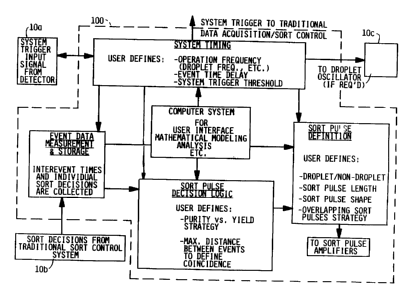
Figure 1 is a block diagram of an embodiment of the
~,~ invention system for sorting particles showing the
interaction of four major functions of the system
and the computer system.
. .~
Figure 2 is a block diagram of a particle sorting system
according to an embodiment of the invention.
Figure 3A is a logic diagram of electrical circuitry for
timing circuitry according to an embodiment of the
invention.
Flgures 3B and 3C are logic diagrams of electrical circuitry
for measurement and storage circuitry according to
an embodiment of the invention.
.
'i, Figure 3D is a logic diagram of electrical circuitry forsort decision circuitry according to an embodiment
of the invention.
~ Figures 3E and 3F are logic diagrams of electrical circuitry
:~ for sort pulse definition circuitry according to an
embodiment of the invention.
Il 35
,~
A;
"
'i'; ' ~ ~ ' ' ' ' ' ' '; '
:, -',. ~ . ' .', ., ~ '' .'' , ' ' ' ', ' . , ~ ' ' , ' ,,' ' ,
,f',, ' "' " , . .'.' ,' . ,.. '',' ,'.'.','. " , ~' ' .. ' ' ~".. : ' . ':
WO92/17288 PCT/US92/02693
. .
3~
~i Figure 4 is an illustration of data available for a look-
up table for a sort pulse decision.
Figure 5 is a schematic block diagram of software modules
according to an embodiment of the invention.
. 1 DE:TAILED DB~CRIPTION
.~
Fig. 1 illustrates a block diagram of a system 100 for
flexibly sorting particles in accordance with the present
invention, used with a prior art flow cytometer cell sorter
10. The four major functions of this sorting system are
system timing, event data measurement and storage, sort
pulse decision logic, and sort pulse definition. A computer
system is also provided for supplying user interface
functions to the functions of the system. The computer
system can also be used for mathematical modeling of the
separation system to assist in defining an appropriate
strategy and/or analysis of the performance of the
separation system. System 100 receives input signals from
photo-detectors 10a and sort,decisions from traditional sort
control system 10b and processes a sorting logic decision
based on a logic condition, i.e. a yield/puri~y ratio.
~' .. , , :. .
Fig. 2 illustrates a preferred embodiment of a system
constructed in accordance with the present invention. The
system receives detection analog input signals from a
particle detector 10a, such as a total signal (TOTAL) at the
system trigger 21. The TOTAL signal represents a signal
generated when any particle passes by a point in the
particle detector, i.e. is detected when passing by a laser
beam. The incoming TOTAL signal is in the range from noise
level to about 10.0 volts, preferably significantly above
noise level. The TOTAL signal is received by a system
trigger threshold comparator 21b which determines if the
received signal has crossed a system trigger threshold
reference voltage. The trigger threshold voltage comes from
. ~ .
J
. . .:
WO92/1728B 21 0 7 '15 ~ PCT/US92/0269~
.~ .
11
a system trigger threshold source 21a whose voltage level is
settable by the user of the system. When the signal received
at the comparator has crossed the trigger reference voltage,
, a TRIGGER signal is generated by the comparator 21b. The
5 TRIGGER signal is applied to an event timer circuit 22, an
inter-event timer circuit 33 and a data acquisition system
, lob for synchronization of the system loo with each of the
j particles detected.
..
~, 10 An oscillator control circuit 23 is used as a system
.~ clocking source. The oscillator control circuit 23 is
,, adjusted to the frequency of the sorting units (e.g.
j droplets). In this embodiment of the invention, an input to
; the oscillator control circuit 23 is user settable and is
'~ 15 adjusted to be 128 times the frequency of the droplet
,~ stream. The oscillator control circuit 23 establishes
clocking rates for different parts of the system by dividing
`~ down the input frequency by selected values with division
circuits 23a-23d to give required frequencies at the
required phases. In Fig. 3A, the dif,ferent frequencies are
shown as CLK 64, CLK 32, CLX 16 and CLK corresponding to the
~ division of the input fr,equency by 2, 4, 8 and 128,
; respectively.
~, 25 In this implementation, system 100 is used for droplet
sorting and, therefore, the system provides a droplet
' oscillator 100. The droplet oscillator lOc is used at the
point at which the fluid stream exits an ejection nozzle of
the flow cytometer into the air. The droplet oscillator lOc
, 30 is used during droplet formation such that droplets are
?, formed in a uniform shape and break off from the fluid
, stream in a stable position. The droplet oscillator lOc
comprises a piezoelectric crystal to provide vibratory
motion for droplet formation. The droplet oscillator lOc
is driven by the oscillator reduced frequency to vibrate the
piezoelectric transducer at a resonant frequency of the
stream. The resonant frequency used in this
.
:~
W O 92/17288 P ~ /US92/0269~
4~3~
12
implementation is 32 XHZ. In this implementation, the
reduced frequency, CLK, to the droplet oscillator lOc is
1/128 of the input frequency. Further, in this
iimplementation of droplet sorting, a variable phase delay
circuit 25 is provided to vary the input frequency to the
droplet oscillator lOc and is connected to a buffer which
leads into a droplet oscillator lOc. The variable phase
delay circuit 25 operates to synchronize the sorting of a
droplet with the sort pulse charged to the droplet such that
~,10 a charge is applied to a whole droplet. Since, depending on
the flow rate, the distance measured from when the droplet
is detected by the system and when a charge is applied to a
droplet may not result in a whole droplet being charged, the
variable phase circuit delay 25 offsets a droplet by
increments of 1/16 of a droplet to align the charging
circuitry with the sorted droplet. Alternative
1implementations which do not use the system for droplet
sorting, for example, destruction of an object by zapping,
cellular injection or selective introduction of material to
.20 an object do not require a droplet oscillator and the phase
delay value is ignored.
Referring to Fig. 2, timing of events of the system is
-~performed with an event timer circuit 22 and an inter event
timer circuit 33. An event timer circuit 22 is provided to
initiate when a sort decision should be made and to
determine when a sort pulse should be applied to a sorting
unit or droplet. The event timer circuit 22 measures the
length of the stream or the time to be delayed as the
particle travels from the sense point to the point at which
a charge pulse is applied to a particle. In this
~implementation, for droplet sorting, the charge should be
-~applied near the point at which droplets break off from the
;~ifluid stream. The event time is a relative constant value
,35 that is defined by the physical separation of the signal
~excitation source from the location at which sorting will
¦occur and the velocity at which the object is traveling
., .
~, .. , , . , : ......... , . . , - . ,. ,, . .~ , . .
"". , , , . ,, ,, . , , " : ,: . ~ , i :i . .. . . .
WO92/17288 2 1 0 7 '1 ~ ~ PCT/US92/0269~
13
between the two locations. In this implementation, the
event time is approximately 650 microseconds and the
velocity at which the cells are travelling is 10 m/sec, and
~, there are from 18-23 droplet lengths from the excitation
^i 5 source to the sorting location.
:,
As shown in Fig. 3A, the event timer circuit 22 comprises
a RAM memory 22a, a counter 22b, a comparator 22c and an
event timer length register 22d. Timing is accomplished in
the event timer circuit 22 with a shift register operation
~ of variable length. In this implementation, the RAM memory
`J~ 22a comprises a 4k x 1 bit RAM with separate input and
^~ output pins. This RAM memory 22a is addressed by the value
of the counter 22b that is continuously incremented at the
CLK 32 frequency described above. When the RAM memory 22a
input receives a TRIGGER signal, a value of 1 is stored in
the RAM location at the address currently addressed by the
~, counter value. As the counter 22b is continuously
incremented, the incremented counter value is inputted to
20 the comparator 22c which compares the counter value with a
length value which is stored in the event timer length
register 22d. The user settable length value is determined
from the physical distance between the excitation point to
the point at which the droplet is charged and the flow rate
25 of the stream. This value is in units of 1/32 of the
droplet period. When the comparator 22c determines the
counter value is the same as the length value, the counter
22b is reset to zero and is continuously incremented from
there in a cyclic manner. A TIME signal is generated by the
30 event timer circuit 22 when the counter 22b has returned to
the value during which the trigger signal was stored.
In this embodiment, as shown in Fig. 2, the system
provides an inter-event timing circuit 33 for measuring the
Y 35 time between system triggers of successive events or inter-
event time. ~his inter-event time is used to determine when
¦ events are coincident. In this implementation, coincident
.~
.i .
~s
.,.. , :, . -,: , , , .. . -. : ..... ~ . ,, ,, .: ., ,
WO92/17288 ~ PCT/US92/0269
14
events are defined as two or more events being close enough
' in proximity to each other in the fluid stream to be in the
same sorting unit, e.g. the same droplet in droplet sorting.
..
Referring to Fig. 3B, this inter-event timing is
accomplished by a counter 33a that is continuously
incremented by the same frequency as the event timer circuit
22, i.e. 32 times the droplet frequency by receiving a CLK32
signal. The counter 33a is responsive to the TRIG&ER signal
such that each time a TRIGGER signal is received the value
of the counter 33a is read into an inter-event FIFO memory
34a. After reading the inter-event time the counter 33a is
reset to zero to begin counting the time to the next event.
In this implementation, the value of the counter is eight
bits and the counter val`ues will range from 0 to 255. In
the case that events are farther apart than the counter's
maximum value, i.e. 255, an overflow of the counter 33a is
latched and infinite separation is assumed.
.
In system 100, as a particle or cell passes a detector,
a data acquisition system lOb determines an individual sort
decision based on the parameters detected for the
characteristics of the detected particle. The individual
sort decision can be a decision to sort the particle, i.e.,
sort right or sort left, or not to sort the particle. A
signal line for each of the sort left or sort right
decisions is fed from the data acquisition system lOb to an
~ individual sort decision storage circuit 32 for storing
-~, individual sort decisions. When the data acquisition system
lOb makes a sort right or sort left decision, a one value is
sent to the individual sort storage circuit 32 on the
appropriate line. If the data acquisition system lOb makes
a no sort decision, a zero value is sent on both the sort
-j~ left and sort right lines. The individual sort decision
storage circuit 32 comprises a sort FIF0 memory 32a and a
predetermined number of latches 32b-32k corresponding to the
number of events or cells which will be available for making
`,,~. ' "
~ '' . .
, ~ . . . ., ,, .. . . , . , . . .. ~ .. . . . . .. . . .
- w092/17288 2 1 ~ 7 ~ ~ 8 PCT/US9~i/0269~
.
a sort decision, as described below. The sort FIFO memory
32a of the individual sort decision circuit 32 is controlled
i by a sort information storage control circuit 31. The sort
-, information storage control circuit 31 is adapted to control
the reading of the sort FIFo memory 32a such that
' information on a current detected cell as well as
~ information on cells which were detected before and after
j the current cell can be latched in appropriate latches 32b-
32k, so that the data in the latches at a particular instant
in time is available for making a sort decision.
The sort information storage control circuit 31 is
responsive to an AVAILABILITY LEVEL variable which indicates
the number of events before and after the currently detected
cell that may be used by the sort decision logic of the
system when making a sort decision. As illustrated in Fig.
4, in this implementation, the AVAILABILITY LEVEL for a sort
decision can have the values of 0, 1 or 2. In the initial
operation of the sort information control circuit 31 the
AVAILABILITY LEVEL is set to "-1", indicating no cells are
available for a sort decision. When the first cell or
current event is detected by the system, the AVAILABILITY
LEVEL will change to "o" as described below, indicating
only the current event or cell can be used in making a
, 2S decision at that instant, since no prior cells were
; detected. The sort decision for the cell detected by the
' - system is considered to be event A, as shown in the first
row of Fig. 4, and may have values of left sort decision or
right sort decision.
The sort FIF0 memory 32a is updated by the sort
information storage control circuit 31 in response to the
¦ CLK32 signal for continuously determining if information on
an event has been stored in the sort FIF0 memory 32a. In
operation of the system the sort FIF0 memory 32a is checked
i at a rate of 32 times per droplet, and if the sort FIF0
memory 32a is empty an empty signal will be sent to the sort
i .
.
- - .
s~ : . , Y . . , .. - .. . -. . ., .. -. , ,:.. . - . ., ~ : ,, .
WO92/17288 PCT/US92/0269~
Q~ ~
16
information storage control unit. A strobe signal is sent
to the sort FIFO memory 32a to indicate an event has arrived
at the sort FIFO memory 32a.
A FIFO READ signal is generated whenever an event has
been stored in the sort FIFO memory 32a, the sort FIFO
~ memory 32a is not empty, and the availability level is less
-~ than AVAILABILITY LEVEL "2". AVAILABILITY LEVEL "2" is the
maximum availability level for this implementation. The
~10 combination of the NOR gate 31a and AND gate 31b are used to
;~generate the FIFO READ signal. The NOR gate 31a operates on
the EMPTY signal and the AVAILA~ILITY LEVEL. When neither
an EMPTY signal or an AVAILABIL~TY LEVEL of "2~ is received,
a FIFO READ SIGNAL is generated to the AND gate 3lb. In
response to the AND circuit receiving a CLR 32, the FIFO
READ signal is applied to the inter-event FIFO memory 34a
~and the sort FIFO memory 32a. If the state of the sort FIFO
1memory 32a, where the FIFO is not empty and the ~VAILABILITY
-~LEVEL is less than 2, indicates that information is
available in the sort FIFO memory 32a, which is available to
be read into the chain of latches 32b-32k, then this
information is made available for sorting decisions.
.. ~ , .
The FIFO READ signal is also applied to counter 31c for
updating the AVAILABILITY LEVEL. Before a FIFO READ signal
is applied to the availability level counter, nothing is in
the queue and both QA and QB of the counter 31c are low or
zero. In response to the first FIFO READ signal, QA is set
to 1, QB remains at 0 and the output of AND circuit is 0,
i.e. AVAILABILITY LEVEL 0. In response to a second FIFO
~;~READ signal being applied to the availability level counter
'~,31c, QA is set to 0, QB is set to 1, the output of the AND
circuit is 0 and the output of QB is one, indicating
AVAILABILITY LEVEL 1. In response to another FIFO READ
~,35 being applied to the counter 31c, both QB and QA are set to
~1 such that the AVAILABILITY LEVEL is set to 2.
"~
~ .
~, .
,1~
W092/17288 PCT/US92/0269~
~ ` ;` 2107 llCj~3
17
~; When the first individual sort decision was received from
the data acquisition system 10b, as described above, a FIFO
READ signal is generated, since the sort FIFO memory 32a is
no longer empty and the AVAILABILITY LEVEL is less than 2.
The sort FIFO memory 32a is responsive to the FIFO READ
signal and the first event stored in the sort FIFO memory is
7 moved into latches 32b, 32g. Therefore, a LEFT A or RIGHT
A decision is available in latches 32b, 32g for making a
sort decision.
`'` 10
~' Once a subsequent individual sort decision arrives at the
sort FIFO memory 32a and is stored in the sort FIFO memory
32a, a FIFO READ signal is again produced, since the sort
FIFO memory 32a is not empty and AVAILABILITY LEVEL is less
than 2, and a signal is applied to counter 31c. In response
to the FIFO READ signal, data in the sort FIFO memory is
read to latches 32b, 32g and the data originally in latches
32b, 32g is moved to latches 32c, 32h, respectively.
.~ -
As illustrated in Fig. 4, the data which was previously
stored in event A is moved to event B when the AVAILABILITY
i LEVEL is set to 1. In this case, AVAILABILITY LEVEL of 0
would indicated a subsequent event was received and stored
in event A and AVAILABILITY LEVEL 1 indicates that the event
data which was previously received and stored in event A is
now stored in event B. Therefore, for AVhlLABILITY LEVEL 1
' when making a sort decision. The sort decision has
3 available the data in event B, the current event to be
sorted, as well as the data in event A, data received after
the current event but before a logic decision is made.
,
3 In the event another individual sort decision is
' received, at the sort FIFO memory 32a, the counter 31c
generates a TWO value at QB to indicate an AVAILABILITY
. 35 LEVEL of two. A FIFO READ signal is generated to move the
~ latched data from 32b, 32g to 32c, 32h and previously stored
! 32c, 32h to 32d, 32i, respectively. At this time, the
., .
"~ .
W092/17288 PCT/US92/02693
18
maximum availability level has been reached for this
implementation and the TWO value from the counter 31c is
applied to the NOR gate 31a to disable generation of the
FIFO READ signal. As shown in Fig. 3, when the AVAILABILITY
LEVEL is set to "2", information is available for events A,
B and C. The value of the counter will remain at TWO until
the time at which a logic sort decision is made. When a
logic sort decision is to be made, a TIME signal from the
event timer is applied to the counter 31c. In response to
. 10 the TIME signal, the counter 31c decrements the AVAILABILITY
~ LEVEL by one, after the logic sort decision has been made.
,~ As shown in Fig. 4, an event which arrives after data has
been previously stored in events A, B and C will be moved
into Event A and move previously stored data in Event A to
~ Event B, Event B to Event C and Event C to Event D by moving
il data from latch 32b to 32c, 32c to 32d, 32d to 32e and 32e
to 32f and data from latch 32g to 32h, 32h to 32i, 32i to
32j and 32j to 32k. In this implementation, event E is the
last Event for storing data corresponding to the maximum
availability for a sorting decision of two events prior to
the event to be stored and two events after the event to be
sorted. Alternative embodiments can include a different
number of latches to correspond to the use of more or less
events before and after the event to be sorted when making
a sorting decision.
~, Referring to Fig. 2, coincident detection circuit 42
~ receives the values of the inter-event value storage circuit
s 30 34 which corresponds to the inter-event times and an over
flow bit value storage circuit for determining if two or
more events, i.e. system triggers, are within a user
specified time period. The time period is established by
the user and is set in the coincident value register 42a
35 with 8 bits so that the value ranges from O to 255. The
coincident value is in the same units as the inter-event
counter values. Digital comparators 42e-42j are used to
J
WO92/17288 21 ~ 7 '1 ~i 8 PCT/US92/0269~
19
"
determine if the coincident value register 42a is greater
than the values received from the inter-event storage
~ circuit 34, thereby indicating the events are coincident.
J The coincident detection circuit 42 includes sum circuits
5 42b-42d which are used to determine if more than two events
are coincident if the distance between two events, A to C,
is less than the coincident value. The sum circuits 42b-42d
sum the lengths between two events, i.e., A to B and B to C,
and the value is compared in respective comparator 42e, 42g
10 and 42i. If the sum of event A to B and B to C is less than
the coincident value, the events A, B and C are coincident.
?
~ The inter-event FIFO memory 34a is read in response to
:~3 _he FIFO READ signal, described above. The FIFO READ signal
',3 15 is used to read information stored in the inter-event FIFO
memory into a chain of latches 34b-34e so that the inter-
event timing information for each object is available when
making sort pulse decisions. On receiving the FIFO READ
signal at the inter-event FIFO memory, the first inter-event
20 corresponding to A to B is read into latch 34b. As FIFO
READ signals are generated, data is moved from latch 34b to
34c, 34c to 34d and 34d to 34e corresponding to inter-events
corresponding to A to B, ~3 to C, C to D and D to E.
',5 25 The sort pulse decision logic circuit 41 uses the
individual sort decisions and inter-event times of nearby
events to generate a sort pulse decision appropriate for the
current event, based on the strategy chosen. This strategy
is user definable and may be altered to allow for any
combination of purity vs. yield to be implemented.
As illustrated in Fig. 3D, a sort pulse decision in this
implementation is made based on 18 conditions and is
~ directed by a user defined strategy (e.g from mathematical
1 35 modeling). The 18 conditions are used as inputs to a sort
pulse decision logic RAM look-up table 41 which is loaded
with a transfer function embodying the user defined
.~
,~ .
,3
",? ~ . ' .. ~ . ' . ~ . . : - :
WO92/17288 PCT/US9210269~
~ 4~
strategy.
The inputs to this look-up RAM table 41 are information
pertaining to up to five available events (i.e. events A
'A 5 through E). Ten of these inputs are the left and right
~ individual sort decisions of each of the five possible
,A~ events (A through E) from latches 32b-32k. Three more
inputs indicate whether, or not, there is coincidence (as
defined above) between neighboring events (i.e. between
~ij 10 events A&B, B&C, C&D) from digital comparators 42e, 42g and
¦ 42i. There are also three inputs that indicate coincidence
j between events that are separated by two (i.e. between
~ events A&C, B~D, C&E) from comparators 42f, 42h a~d 42j.
In this embodiment coincidence is defined by setting a
.
register with the maximum time spacing at which two events
will be considered coincident. -This value is in units of
1/32 of the droplet period and is used as the compare value
with the inter-event counter values stored at each system
trigger.
Two more inputs to the RAM look-up table 41 are used to
indicate the number of available future events as described
above (AVAILABILITY LEVEL). The availability level also
!~ 25 indicates which information is that of the current event
(i.e. for AVAILABILITY LEVEL 0, event A is the current
event; for AVAILABILITY LEVEL 1, event B is the current
event; for AVAILABILITY LEVEL 2, event C is the current
~ event). The transfer function of the look-up table (i.e.
-~ 30 strategy) may be developed using boolean logic on mode
control variables. Some examples of boolean variables that
may be used are:
1: SORT LEFT ENABLE
Enables the sort left output.
2: SORT RIGHT ENA~LE
Enables the sort right output.
`:W092/1728X 21~ 7 ~ ~ 8 PCT/US92/0269~
21
3: LEFT ANTICOINCIDENCE WITH RIGHT ENABLE
Generates left sort outputs such that they
will not be coincident with right sort
events.
4: RIGHT ANTICOINCIDENCE WI~H LEFT ENABLE
Generates right sort outputs such that they
will not be coincident with left sort events.
5: LEFT ANTICOINCIDENCE WITH NEUTRAL ENABLE
Generates left sort outputs such that they
will not be coincident with neutral (neither
;, left nor right sort) events.
' 6: RIGHT ANTICOINCIDENCE WITH NEUTRAL ENABLE
. Generates right sort outputs such that they
will not be coincident with neutral (neither
left nor right sort) events.
'7 7: LEFT - CHECK NEAR NEIGHBOR ENABLE
, Generates left sort outputs taking into
~ consideration the coincidence of events that
;~ are immediately preceding or following the
'3 20 event in question.
i 8: RIGHT - CHECX NEAR NEIGHBOR ENABLE
Generates right sort outputs taking into
consideration the coincidence of events that
are immediately preceding or following the
event in question.
9: LEFT - CHECX FAR NEIGHBOR ENABLE
Generates left sort outputs taking into
consideration the coincidence of events that
:~ are two events preceding and two events
following the event in question.
10: RIGHT - CHECX FAR NEIGH80R ENABLE
Generates right sort outputs taking into
consideration the coincidence of events that
are two events preceding and two events
following the event in question.
LEFT SORT DOMINANCE ENABLE
When an event has an individual sort decision
t
WO92/17288 PCT/US~2/0269~
2 2
,, that is in overlapping regions (both sort left
and sort right) it will be treated as a sort
1 left individual sort decision.
`$1 12: RIGHT SORT DOMINANCE ENABLE
, 5 When an event has individual sort decision -
-s that is in overlapping regions (both sort left
and sort right) it will be treated as a sort
~ right individual sort decision.
';~
In alternative implementations, other variables may be
defined and algorithms to control them in order to generate
~ a look-up table corresponding to a wide range of experiment
,~ environments.
Other non-boolean variables can be incorporated into the
strategy to define a purity/yield ratio giving a minimum
purity requirement.
In this Case, the user defines a maximum acceptable
purity level (given as percent here for example) and that
; purity is compared as a threshold to the sort unit under
consideration. Examples of rules used in the sort pulse
decision logic for sorting in a single direction are as
follows:
1: IF TWO CELL ARE COINCIDENT WITHIN A SINGLE SORTING
UNIT
- if only one is desired then 50% purity results.
- if both are desired then 100% purity results.
:
2: IF THREE CELLS ARE COINCIDENT WITHIN A SINGLE SORTING
UNIT
- if only one is desired then 33% purity results.
- if two are desired then 67% purity results.
- if all are desired then 100% purity results.
, ~ . .
3: IF FOUR CELLS ARE COINCIDENT WITH A SINGLE SORTING
UNIT
- if only one is desired then 25% purity results.
- if two are desired then 50% purity results.
:
i~.',.: ,, '' .' . ' ' ': . ' " . . ', . '.,' ', '.. : '' ;:' '- ' : ' ',
~ W092/17288 PCT/US92/0269~
2107~g
23
- if three are desired then 75% purity results.
- if all are desired then 100% purity results.
4: IF FIVE CELLS ARE COINCIDENT WITHIN A SINGLE SORTING
UNIT
. - if only one is desired then 20% purity results. - if two are desired then 40% purity results.
- if three are desired then 60% purity results.
~' - if four are desired then 80% purity results.
' - if all are desired then 100% purity results.
~s
~l, 15 In this strategy, we assume that the arrival statistics
'~ of each cell subpopulation (e.g. desired, undesired) are
independent of each other. Prior knowledge of the overall
percentage of each cell type is then used to develop an
overall model of the probability of each cell type for each
of the above sorting unit rules to determine the yield of
each sorted subpopulation.
,''.'
Each of the above conditions may be separately defined as
a sort or no sort condition. By incorporating these rules
with a knowledge of the statistical probability of each
condition occurring (i.e. a mathematical model), an
optimized strategy can be developed.
Other examples of purity driven strategies consider other
conditions and permutations such as the conflicting purities
of "sort right" and "sort left" cells (i.e. two direction
sorting) in making a sort decision.
In a preferred embodiment, the look-up table is
implementated in RAM 41 to allow a flexible definition of
the sort pulse decision process. The look-up table 41 may
be quickly altered by the user to define special modes of
operation by loading it with new transfer data which may
have been generated earlier. The output of the look-up
table is a sort left or sort right logic decision.
,,
~- WO92/17288 ~ ~ PCT/US92/0269
24
Referring to Figs 2 and 3E, there is shown a sort pulse
timing control circuit 51 for starting the sort pulse in
response to the TIME signal from the event timer circuit 22
indicating the time for the droplet to travel from the
i~ 5 detector to droplet break-off has lapsed. The sort pulse
u~ timing control circuit 51 only applies a sort pulse to
s droplets which are to be sorted. A sort left or sort right
~ decision from the sort pulse decision logic circuit 41 is
received at the D input of latch 51a and latch 51b,
10 respectively. The latches are synchronized with a CLK
signal in order to synchronize the pulse with a droplet.
The sort pulse timing control circuit 51 operates on the
condition that the droplet must be physically sorted either
left or right and can not have both a sort left and sort
15 right condition concurrently. In this implementation, the
sort pulse timing control circuit 51 determines a condition
as either sort left or not sort left. If a left sort is
received at latch 51a, the Q output of latch will be high
and will be fed to latch 51e as the D input. The latch 51e
20 will output a LEFT SORT signal. Also, the Q output of latch
51a is applied to an OR gate 51d to be combined with the Q
output of latch 51b. Since a LEFT SORT decision was
received at latch 51a, a high signal is generated as input
to ONE-shot latch 51f which generates a STA~T pulse. The
25 ONE-shot latch operates on a CLK signal which is delayed by
100 nsec with a digital delay circuit 51c to account for the
.
time needed for the latches to propagate. If a right sort
decision, is received at latch 51a, a START signal will be
generated by ONE-shot latch 51f, but a left sort decision
30 will not be generated by the sort pulse timing control
~; circuit 51. Therefore, indicating a not left condition.
The left sort signal and the START signal are applied to
a sort pulse definition circuit 52 to define the sort pulse
for each of the two directions. The pulse is defined by a
series of amplitude values (8-bit) stored in a left sort
pulse shape RAM 52e and right sort pulse shape RAM 52f. The
;~
,~1
W092/17288 PCT/US92/0269~
- 21~7~8
.
sort pulse shape definition data may be defined using many
different techniques including, but not limited to,
mathematical waveform description, real waveform capture and
digitization or some combination thereof. The resulting
data is then loaded into the sort pulse definition circuit's
3, left sort pulse shape RAM 52e and right sort pulse shape RAM
52f. When a START pulse signal is received by the sort
pulse definition circuit 52, the values in either the left
` sort pulse shape RAM 52e or the right sort pulse shape RAM
52f, in response to the presence or absence of a left sort
, condition, are sequentially output to a digital-to-analog
converter (DAC) 521 for the left sort pulse shape RAM 52e,
or 52m for the right sort pulse shape RAM 52f at a frequency
of 64 times the oscillator frequency. The DAC's 521 or 52m
output is used to define the shape of the sort pulse. In
j this implementation, the output voltage is between 0 - 5
-~ volts. This output is amplified to a higher voltage value
.~3 if required by external amplifiers 53 or 54, i.e. up to 10
times the voltage from the DAC.
The values in the left sort pulse RAM 52e and right sort
pulse RAM 52f are addressed for the DAC 521 or 52m by an
address counter 52d which is started when a start pulse is
received by latch 52c. This address counter 52d is
incremented at a frequency of 64 times the droplet
oscillator frequency. The address counter 52d continues
until a user determined pulse length set by the pulse length
register 52k has been reached. A pulse length register 52k
,' stores predetermined values for the length of the pulse to
determine the number of droplets which the pulse will be
applied to, for example, the length value would be 64 for a
1 droplet length pulse or 128 for a 2 droplet length pulse.
At this time, the address counter 52d is reset to zero, the
~ sort pulse is stopped and the sort pulse definition circuit
:~ 35 52 is ready to receive another START sort pulse signal.
.
.
;l
":
wo g2/~iq ~ Pcr/uss2/026s3
f.
26
If a START sort pulse signal is received while a sort
pulse is already in progress, the address counter 52d that
addresses the RAM data will be set to a user defined value
and the sort pulse continues from there. This value in
restart position register 52b, defines the position in the
pulse definition where an overlapping sort pulse should
begin to avoid pulse distortions caused by pulse rise
profiles being executed mid-pulse. This allows long pulses
to overlap without causing a distortion of the pulse shape.
The pulse length may continue for multiple pulses, each
pulse overlapping the one before it. A left idle data
register 52g and a right idle data register 52h are provided
to define the output value of the sort pulse while that sort
direction is disabled (i.e. a sort pulse in another
direction is in progress).
.~
System 100 maintains two possible sort directions and
allows each sort direction to have a separately definable
~ sort pulse shape. Both of these sort pulses have a separate
-~ 20DAC, 521 and 52m, and output by external buffers 52n and 53O
3 which may be combined into a composite sort pulse by
amplifier circuits 53 and 54. Since only one address
~ counter is used in this implementation, pulses are generated
;l for only one output at a time while the other is disabled.
The RAM address counter 52d enables the left sort RAM if a
left sort signal is received and enables the right sort RAM
if a left sort signal is not required. A user defined value
~ is output when a sort direction is disabled. It is assumed
-- that the anti-coincidence circuitry above is adjusted such
-,30 that overlapping pulses of opposite direction will not
~ occur.
':~
¦In a preferred embodiment of the present invention, the
jsystem 100 provides a Q-bus extension to a PDP-11/73
computer system which is used to implement user interface
and system setup functions. In alternative implementations
other co=puter systems may be used to perform these
,~
.~
~;., , ~ , . - ,,, , ~: , , -, , -
~ WO92/17288 2 1 ~ 7 ~ ~ 8 PCT/US92/02693
27
functions, i.e. an IBM PC/AT compatible personal computer
(pc~ The PC is a more widely available platform a~d would
thus allow implementation of this system over a wider range
of applications. The Pc platform can also be used for
mathematically modeling our systems and sort control
strategy planning.
As illustrated in Fig. 5, in this implementation a
software algorithm is used to identify the optimal sorting
strategy. The algorithm uses information from the cell
sorter operation which include individual sort or no sort
! decision from the traditional sort control 10, i.e. event A,
' B, C, D, E and inter-event A to B, B to C, C to D, D to E,
;~ which are the same inputs stored in the RA~, 41 as the
' 15 information from the detection signals generated in response
j to the respective particles passing a selected point of the
flow cytometer. Further, the alogrithm uses arrival
¦ statistics of the particles, i.e. poisson, and conditions of
~; the instrument, i.e. signal/noise ratio, coefficient of3 20 variation of the signals or deadtime between particles, to
enable particles to be separated on determination of a
yield/purity ratio that is specific to the implemented
hardware. Specifically, the coefficient of variation of
signals is used to offset variations of the instrument
25 caused by the environment of the instrument, i.e.
temperature or humidity. The algorithm may also use
information not from system 100 such as user defined logic
~j conditions for yield/purity ratios and prior knowledge about
a particular experiment. For example, prior knowledge may
30 include stain spectra and a value of the number of cell
. subpopulations present in the sample. The algorithm
optimizes the yield/purity ratio according to the
information received. The algorithm provides the logic for
~ the RAM look-up table (LUT) to determine a sort decision and
3 35 controls the hardware circuitry of system 100. After a
decision has been made to sort or not to sort the droplet,
the sort result is passed to a learning algorithm to
:.
.
-- W O 92/17288 , ~l P~T/US92/0269~
~a~t ~-~ V
28
identify if the sort decision resulted in the correct
yield/purity ratio and to modify the algorithm to optimize
the desired yield/purity ratio.
i
In an alternative embodiment, each sort direction may
have its own separate address counter and thus allow
' overlapping sort pulses of many sort directions to be
implemented to allow any number of possible pulse shapes to
be used as a dynamic function of current conditions. An
example of this feature may be to use different charge
shapes (droplet sorting) if the object was in the neck area
of the droplet at breakoff. Another use would be to alter
the pulse shape (including duration ) and/or amplitud-
depending on number and/or type of objects within a given
sorting unit.
.. .
Another alternative embodiment of the invention, monitors
events which are characterized as "missed events". A
"missed event" is defined as an event which arrives during
the time intervals that the traditional sort control system
is analyzing a previous event and the "friend" or "foe"
status of that event is, therefore, unknown. ~'Missed-event"
information may be used by the sort pulse decision logic
since there are applications (e.g. sorting of rare cells)
where the "friend" or "foe" status of the "missed-event" may
or may not be relevant for subsequent processing of the
sorted cells.
Further, alternative embodiments may use system lOO for
purposes other than sorting. The sorting function may be
replaced by any function desired to be performed on an
object in flow. Examples of this may include, but are not
limited to, selective chemical injection of objec's (e.g
cellular injection), selective destruction of objects (e.g.
zapping), or selective introduction of catalytic force or
material to an object. In a further alternative embodiment
the system may be used with systems other than flow systems.
~,':", ' ,' , ' . .
' ~,', ' ' ' ' ~ , . ' ' '
' ~, ' , ' ~ ' '. ' ' ' ' " ' 1 '
`W O 92/17288 210 ~ PC~r/US92/02693
29
Any system in which objects are in closer proximity than the
~function's effector can resolve could use System 100.
:
In an alternative embodiment, the traditional sort
control which provides a binary sort/no sort decision may be
.replaced with a non-binary decision. In this implementation
the logic of sorting system would be coordinated to
.determine a sorting decision using the non-binary decision
values.
-~Another alternative embodiment of the invention monitors
an event's relative position within the sorting unit. This
may be used as an alternative means of detecting coincidence
of multiple events. This relative position may also have a
probability "confidence factor" associated with it, for
example to allow for the small instabilities in droplet
l,formation.
iIt will also be appreciated that various modifications,
9~20 alternate construction and equivalents may be employed
~without departing from the spirit and scope of the invention
¦and that, therefore, the above description and illustration
should not be construed as limiting the scope of the
invention, which is defined by the appended claims.
~;) 25
~; '
,1
:'
.,
~ :
., ~
, ' ~.
,~ .
-
1 .
; , . - . . .. ... .
.... . . . . .. . .. . . . ..... . .