Note: Descriptions are shown in the official language in which they were submitted.
7 r^ ~ i$
-- 1 --
P~OCESS FOR TH~ DRIVTNG OF A TUNNEL AND TUNNEL BORERS THEREFORE
The invention relates to proce~ses and apparatus for the driving of
a tunnel into geologlcal rock formations which include hard rock
obstacles.
One method of driving a tunnel into a rock formation includes
cu~ting and removing the rock at the head wall of the tunnel being
driven, whereby a self-propelled tunnel borer with loose rock r~moval
arrangement is used. The term tunnel is intended to include also mining
tunnels or drifts. The term rock includes all geological formations
which are encountered during the driving of a tunnel. Different ~unnel
driving machines are known for She cutting and removal of rock at the
head wall of the tunnel being driven. For example, partial cro~-section
tunnel driving machines are known which cut the rock at the head wall in
15 only a portion of the tunnel cross-section. One type of such partial ~;
cross-section borers has a swivelled arm and cutting heads which rotate
in axial or transverse direction of the arm. Other types of partial
cross-section tunnel driving machines in the form of shield apparatus are
also known. Continuous-miner type machines are a further cla~s of ~unnel
borers wh~ch include at least one scraping roller that extends transverse
to the tunnel driving direction. Finally, full cross-section borers are
known which cover the whole tunnel cross-section with an appropriate full
section cutting head and include roller chisels or scraper chisels.
Problems are often encountered in the driving of a tunnel in the
above described geologic formations when the tools used for the cutting
of the rock encounter a hard rock ob~tacle. The term hard rock obstacle
in thi~ context refers to portions in the geological formations which are
made of very hard rock that can~ot be removed or only with difficulty
with the tools conventionally used on tunnel borers. If conven~ional
tunnel driving equipment encounters a hard rock obstacle in the head wall
of a tunnel being driven, the driving operations for which the tunnel
borer is equipped must be interrupted. For example, the tunnel driving
machine must be completely backed off the head wall under great cost and
the hard rock obstacle removed at further cost with additional equipmene
which is not integrated in the tunnel driving machine and the function of
which does not blend into those of the tunnel drivin8 machine.
. -:
: : : :~ . -: : .
2 :~ 3 ~ ! 3
-- 2 --
~ xplo~ive charges are known from other areas of technology and
originally from the area of weapon technology (see the Journal "Gluckauf"
128 (1992), Nr. 8, page~ 623 to 626). ~xplo~ive charges are used
sometimes for the disintegration of rock obstacles. However, the
integration of plosive charge technology with tunnel driving processes
has not been realized to date.
It is now an ob~ect of the inven~ion to provide a process for the
driving of a tunnel ~nto geological rock formation~ including hard rock
obstacles, by which any hard rock obstacles encountered can be removed at
low cost and without total interruption of the tunnel driving process.
It i8 a further ob~ect of the invention to provide tunnel driving
machines adapted for carrying out that proces~.
This ob~ect is achieved in accordance with the invention with a
process wherein a tunnel iB driven lnto a geological rock formation with
a conventional tunnel borer which is equipped with an explosive charge
firing means for the blasting of any hard rock obstacles encountered by
firing an explosive charge at the obstacle and removing the disintegrated
hard rock of the obstacle with the loose rock removal arrangement of the
tunnel borer.
hccordingly, the invention provides a process for the driving of a
tunnel into geological rock formations which include hard rock obstacles,
the process comprising the steps of:
a) driving the tunnel into the formation by cutting rocks in
forward directlon from the head wall of the tunnel being driven
and removing loose, cut-off rock,
b) stopping the cutting operation when a hard rock obstacle is
encountered,
c) firing at least one explosive charge at the hard rock obstacle
to disintegrate the hard rock obstacle and removing the
resulting di~inteBrated hard rock,
whereby the size and type of the explosive charges, the distance of the
explosive charge from the hard rock obstacle upon detonation (blasting)
and the detonation itself of the explosive charge are selected such that
the disintegrated hard rock can be removed with the apparatus used for
the cutting of the head wall and removal of the loose, cut-off rock.
.: :
- . -~, ~,
6~ 3
-- 3 --
Very different effects can be achieved with explosive charges of
different types and sizeq (see the Journal "Gluckauf" suDra). Thus, with
appropriate selection of the type and size of ehe explosive charge a very
controlled disintegration of the hard rock of any hard rock obstacles
encountered can be achleved so that the disintegrated hard rock can be
removed with the loose rock removal arrangement already provided on
conventional tunnel borers. The required size of the explosive charge
which depends on the hardness of the rock encountered can be easlly
determined by experiment or can be calculated by known method3 (see
Journal of Explosives and Propellants. ~.O.C. - Taiwan 7, 9-24, 1991).
It is surprising that the charge can always be ~elected such that the
disintegrated hard rock can be removed with the loose rock removal
arrangement already included in known tunnel borers. Furthermore, the
aiming of the explosive charge at the hard rock obstacle can be achieved
or assisted by the tunnel borer itself either by ad~ustment of the
cutting arm to which a launcher for the charge i9 mounted or by
re-positionning the whole borer apparatus.
In particular, several possibilities exist for carrying out or
optimizing the process in accordance with the invention. In one
preferred embodiment, a partial cross-section tunnel borer is u~ed which
include~ at least one movable cutting arm and a cutting head mounted
thereon as well a~ an explosive charge launcher that is mounted on the
cutting arm and aimed at the hard rock obstacle by ad~ustment of the
cutting arm position and, if required, by re-positionning of the tunnel
borer. The cutting arm position may be ad~ustable in horizontal and/or
vertical directlon. It will be readily appreciated by an art skilled
person that the explosive charge launcher may also be movably affixed to
the arm to allow ad~ustment of the launcher position in three
dimensions. With this constructiDn, the explosive charge launcher can be ~ -
easily and exactly aimed at the hard rock obstacle. It is further
possible with thid construction to aim at least one explosive charge
launcher which is mounted on the side of the tunnel borer at the hard
rock obstacle. A continuous-miner type tunnel borer can also be used
which has at least one explosive charge launcher mounted on the side of
the tunnel borer machine frame. In this preferred arrangement, the
explosive charge launcher position is al~o ad~ustable in three
~ 3 ~
-- 4 --
dimension3. It can further be aimed at the hard rock obstacle by
re-positionning the whole continuous-miner type tunnel borer. In another
preferred embodiment of the inventlon, a full cross-section tunnel borer
is used which include~ a full ~ection cutting head and a firing opening
therein for the passage of an explosive charge, and an explosive charge
launcher mounted on the machine frame whereby the firing opening can be
po~itioned in front of the launcher and the launcher aimed at the hard
rock obstacle through the firing opening when the cutting head is
stopped. The me&ns required for the aiming of the explosive charge
launcher and the alignment of the firing opening of the cutting head can
be readily achieved with modern drive, transmission and control
technology components.
In a further preferred embodiment of the process of the inventlon
the tunnel borer i~ provided with a hard rock ob3tacle locator and the
aiming of the explosive charge can be controlled according to the
location data detected by the locator. The location data are preferably
input into a computer which then controls the aim of the explosive charge
launcher and/or the po~ition of the cutting arm and/or the whole borer
depending on the location data. The s1ze and/or type of the explosive
charges, the distance of the explosive charges from the hard rock
obstacle upon detonation and the explosive charge detonation itself are
controlled by the computer in accordance with a program that take~ the
respectively encountered hard rock type into consideration. The
explosive charges are preferably automatically fed to the explosive
charge launcher.
The invention also provides tunnel borer~ which are especially
suited for carrying out the proces~ in accordance with the invention.
Accordingly, the invention further provides a tunnel borer which
includes at least one movable cutting arm and a cutting head mounted
thereon, an explosive charge launcher mounted on the borer for aiming at
a hard rock obstacle encountered. The launcher may be mounted on the
cutting arm and/or on a machine frame of the borer and aimed at the
obstacle by movement relative to the arm, movement of the arm or
re-po~itionning of the borer.
~ ,
- . ~, ...
, ~ ,,,.",~
~ ~ ~J 7 ~
-- 5 --
Tunnel borers in accordance with the invention are further described
in the following by way of example only and with reference to the
attached schematic drawings wherein,
Figure 1 illustrates a side elevation of a partial cross-section
tunnel borer ln accordance with the invention;
Figure 2 is a top view of the embodiment shown in Figure l;
Figure 3 is a side view of another embodiment of a partial
cross-section tunnel borer in accordance with the invention;
Figure 4 is a top view of the embodiment shown in Figure 3;
Figure 5 is a side view of a further embodiment of a partial
cross-section tunnel borer in accordance with the invention;
Figure 6 is a top view of the embodiment of Figure 5;
Figure 7 is a side view of a modified partial cross-section tunnel
borer of the type shown in Figure l;
Figure 8 is a top view of the embodiment of Figure 7;
Figure 9 is a side view of a continuous miner tunnel borer in
accordance with the invention;
Figure 10 i9 a top view of the embodiment of Figure 9;
Figure 11 is a side view of another continuous miner tunnel borer;
Pigure 12 is a top view of the embodiment of Figure 11;
Figure 13 is a front view of a full cross-section tunnel borer; and
Figure 14 is a ~ection taken along line A-A through the embodiment
shown in Figure 13.
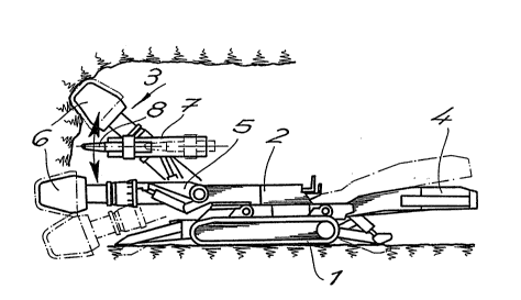
The tunnel borers illustrated in the attached figures always include -
an undercarriage 1, a machine frame 2, a cutting arrangement 3 for the
production of the rock and a rock removal arrangement 4. The latter -
con~ists of a loading arrangement and a conveyor.
In the embodiments according to Figures 1 to 8, the tunnel borer i8
a partial cross-section borer and includes a self-propelled machine frame
2, at least one movable cutting arm 5 and a cutting head 6 mounted
thereon. At least one explosive charge launcher 7 is mounted on the
cutting arm 5, whereby the explosive charge launcher is aimed at the hard
rock obstacle by ad~ustment of the cutting arm position. The arrows in
these drawings indicate the degree of free movement of the explosive
charge launchers 7 which allows aiming of the explosive charge launcher
and, thus, an explosive charge 8 supported thereon, at a target. In the
r
y~c~r~
embodiment according to Figures 7 and 8 further explosive charge
launchers 7 are mounted on both sides of the machine frame 2, which
launeher~ can be aimed at a hard rock obstacle by movement of the cutting
arm 5 and if required, re-positioning of the tunnel borer.
Figures 9 to 12 ~how continuous miner tunnel borers which are
especially adapted for the practicinK of a process in accordance with the
invention. An exploslve charge launcher 7 is positioned at both sides of
the machine frame 2. The launchers 7 can be aimed at a hard rock
obstacle in the manner de~cribed above and, if required, by
re-positionning of the borer.
Figures 13 and 14 illustrate a full cross-section tunnel borer. A
firing opening 10 for the passage of the explo~ive charge 8 i9 provided
in a full cross-section cutting head 9 of the apparatus. One explosive
charge launcher 7 is integrated into the machine frame 2. The firing
opening 10 can be positioned in front of the carrier by appropriate
rotational movement of the cutting head 9. The explosive charge launcher
7 is aimed at the hard rock obstacle through the firing opening by taking
into consideration the clearance provided by the firing opening 10. In
order to allow the firing of explosive charge~ at any point on the head
wall, ~everal firing openin4s 10 and explosive charge launchers 7 may be
provided in the full section cutting head 9 and on the machine frame 2
respectively. A hard rock locator equipment 11 is preferably integrated
into the borer ~hich locates hard rock obstacles in the head wall and the
aim of the explosive charge launcher 7 i~ preferably controlled depending
on the location data detected.
Changes and modificationx in the specifically described embodiments
can be carried out without departing from the scope of ~he invention
which iB intended to be limited only by the scope of the appended claims.
:., ' :- ' ,. : ~ ~ :