Note: Descriptions are shown in the official language in which they were submitted.
~7742
.
LUFFING JIB BACKSTOP ASSEMBLY
BACKGROUND OF THE INVENTION
The present invention relates to lift cranes,
and more particularly to a luffing jib backstop
arrangement for lift cranes.
Lift cranes include a boom attached to the
crane bed upper works, and many times include a luffing
jib pivotally attached to the top of the boom. In a
tower crane configuration, the boom of the crane
extends essentially vertically from the crane bed. The
top end of the luffing jib may be raised and lowered,
thus changing the angle of the luffing jib with respect
to the boom. This is accomplished by the crane
operator using winches and cables, controlled from the
crane cab. Loads are suspended from a cable carried by
a sheave at the top end or head of the luffing jib.
The load may be positioned by raising and lowering the
luffing jib and/or (except for tower cranes) the boom,
retracting or letting out a length of cable, or a
combination of the foregoing.
Cranes with luffing jibs generally incor-
porate backstop pendants to limit the operating angle
of the luffing jib with respect to the boom. This is a
safety precaution because the boom and luffing jib are
constructed and rigged to operate only where the
luffing jib extends from the boom at an angle less than
180. By limiting the operating angle of the luffing
2ie77~
-- 2 --
jib, the backstop pendants prevent the luffing jib from
going over backwards upon the sudden release of the
load, upon a wind gust, or when the jib/strut/pendant
system center of gravity is to the rear of the hinge
point and overtakes the jib dead weight (unloaded jib).
The backstop pendants are generally attached at one end
to the boom in the area of the boom head and at the
other end of the pendant to the luffing jib in the area
of the butt end of the luffing jib. Because the
pendants are of a fixed length, the pendants prevent
the luffing jib from rotating with respect to the boom
beyond the safe operating angle, which is less than
180 for all cranes.
The present invention is directed to the
problem associated with attaching the backstop pendants
to the crane prior to operational deployment of the
crane. For instance, because the pendants are of a
fixed length and are generally attached in the areas of
the boom head and luffing jib butt, the luffing jib
must be rotated with respect to the boom to an angle
within the desired operational limits of the crane
before the pendants can be attached. Since the boom
and the luffing jib are usually laid out along the
ground during assembly and prior to deployment, this
rotation must be accomplished by elevating the boom
head and luffing jib butt. The boom head and luffing
jib butt, and thus the pendant attachment points, are
then a significant distance above the ground. A worker
21~742
- 3 -
then has to be positioned far above the ground in order
to attach the pendants, usually by means of a very tall
ladder or a man-lift, with the attendant logistical and
safety concerns.
One former approach to solving this problem
involved attaching the pendants to the luffing jib head
or the boom butt. Ground level access to the
attachment points was thus permitted even though the
boom head and luffing jib butt were raised in the air.
However, according to this particular solution, the
pendants must span nearly the length of the luffing jib
or boom. Because of their length, the pendants add
significantly to the weight of the crane structure.
This additional weight results in reduced lift
capacity. Also, multiple pendants of different lengths
are then required if the length of the boom or luffing
jib on the crane is changed.
SUMMARY OF THE INVENTION
A luffing jib backstop assembly for limiting
rotation between a luffing jib and a boom to which the
luffing jib is attached has been invented. The
assembly comprises at least one backstop pendant
attached at a first end to the luffing ]ib and at a
second end to the boom, the pendant having a length
sufficient to allow the luffing jib to be extended to
an angle of 180 with respect to the boom. The
assembly further comprises a deployable member which
21077~
- 4
engages the backstop pendant and which, upon full
deployment, holds a portion of the backstop pendant
away from the boom and luffing jib such that the
pendant and deployable member prevent the luffing jib
from rotating with respect to the boom beyond a
permissible operating angle.
The deployable member preferably comprises
two telescopic struts which are attached at a first end
of the telescopic struts to the boom adjacent the point
at which the luffing jib and the boom pivot with
respect to one another. A first pair of wire ropes are
attached between the second end of the telescopic
struts and the boom. A second pair of wire ropes is
attached between the second end of the telescopic
struts and the luffing jib. One of each pair of the
wire ropes then act in concert as a backstop pendant.
Upon full extension of the telescopic struts, slack in
the backstop pendants is drawn up, and the effective
length of the backstop pendants is reduced. Latches
are provided which fix the length of the telescopic
struts in their extended position.
The invention permits the ground level
attachment of the pendants prior to the operational
deployment of the crane. Because the telescopic struts
draw up the slack in the pendants after the pendants
are fully attached, the pendants may be attached when
the luffing ~ib and the boom are at an angle with
respect to one another that is beyond the desired
Z~7~Z
- 5 -
operational limits of the crane. The invention also
permits the use of a single set of backstop pendants
for cranes of varying geometries; that is, cranes
having differing luffing jib lengths, boom lengths, or
any combination thereof.
In the preferred embodiment, the invention
further includes a mechanism for disengaging the
latches used to fix the length of the telescopic struts
in their extended position. The mechanism provides for
the remote disengagement of the latches, permitting the
latches to be disengaged while the boom top and luffing
jib butt are still in the air. The entire boom and
luffing jib assembly is then lowered to the ground.
These and other advantages of the present
invention, as well as the preferred embodiment thereof,
will best be understood in view of the appended
drawings, a brief description of which follows.
BRIEF DESCRIPTION OF THE DRAWINGS
FIG. 1 is a side view of a crane of the
preferred embodiment of the present invention, with the
boom and luffing jib laid out along the ground.
FIG. 2 is a side view of the crane of Fig. 1
with the boom elevated.
FIG. 3 is an enlarged side view of the region
of the crane of Fig. 1 where the boom and the luffing
jib are pivotally attached.
- 6 -
FIG. 4 is an elevational view of the tele-
scopic strut assembly taken along lines 4-4 of Fig. 3.
DETAILED DESCRIPTION OF THE DRAWINGS AND
PREFERRED EMBODIMENTS OF THE INVENTION
FIG. 1 shows a crane 10 positioned prior to
operational deployment. This crane generally comprises
lower works 11, upper works 12, and a boom 20 to which
is pivotally attached a luffing jib 30. The boom 20
and luffing jib 30 are laid out essentially parallel to
one another along the ground. This positioning of the
boom 20 and luffing jib 30 facilitates the ready
attachment of the backstop pendants 40 at ground level.
The backstop pendants 40 (only one of which is shown in
the side view) are attached at either side of the crane
boom 20 and luffing jib 30.
The crane is further comprised by a luffing
jib backstop assembly comprising a deployable member 50
to which the backstop pendants 40 attach. In the
preferred embodiment, the luffing jib backstop assembly
actually utilizes a pair of telescopic struts 60, as
shown in FIG. 4, though only one of the struts 60 can
be seen in the side views of Figs. 1-3.
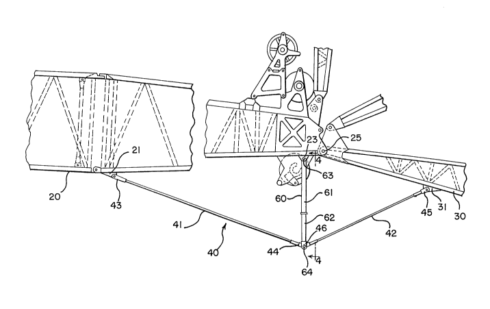
As shown in FIG. 3, a first end 63 of the
telescopic strut 60 of the preferred embodiment is
pivotally attached to the boom 20 at point 23 adjacent
the point 25 at which the luffing jib 30 and the boom
20 pivot with respect to one another. The telescopic
strut 60 of the preferred embodiment comprises a strut
~1~774~
7 -
outer tube 61 and a strut inner tube 62. The strut
inner tube 62 slides freely within the strut outer tube
61.
As shown in FIG. 3, the strut inner tube 62
extends outwardly from within the strut outer tube 61.
Prior to this state of deployment, the strut inner tube
62 is almost wholly positioned within the strut outer
tube 61 of the telescopic strut 60, as shown in FIG. 1.
Deployment of the strut inner tube 62 effectively
lengthens the telescopic strut 60.
Each backstop pendant 40 preferably comprises
two pieces of wire rope 41 and 42. Alternatively, each
pendant may comprise tension bars or other tension
members. Wire rope 41 is attached at first end 43 at
point 21 to the boom 20 in the general area of the boom
head and at second end 44 to the second end 64 of the
telescopic strut 60. Wire rope 42 is attached at
second end 45 to the luffing jib 30 at point 31 in the
general area of the luffing jib butt and at first end
46 to the second end 64 of the telescopic strut 60.
In the pre-deployment position shown in
FIG. 1, slack is present in the backstop pendants 40.
This slack is visualized in FIG. 1 as an arc in the
backstop pendants 40. This slack facilitates attach-
ment of the pendants 40 to the crane at points 21 and
31 on the boom 20 and luffing jib 30, respectively, and
to the second end 64 of the telescopic strut 60.
~ 2 ~ 077~2
-- 8
Attachment is possible because the telescopic strut 60 is in its
retracted rather than extended position.
As shown in FIGS. 1 and 2, the length of the backstop
pendants 40 relative to the length of either the boom 20 or
luffing jib 30 is small. It is also evident that the lengths of
the pendants 40 are independent of the lengths of the boom 20 or
luffing jib 30. Thus, a single set of backstop pendants 40 may
be utilized for any boom and luffing jib combination.
FIG. 2 shows the crane of FIG. 1 after the first step
of operational deployment. The boom 20 has been raised and the
luffing jib 30 permitted to pivot with respect to the boom 20.
The luffing jib 30 may incorporate a multiposition jib erection
support member. At this particular position, the deployable
member 50 is fully deployed, that is, the second end 64 of strut
60 is at its maximum distance from the boom 20.
In the preferred embodiment, upon raising the boom 20
and pivoting the luffing jib 30 with respect to the boom 20, the
weight of the backstop pendants 40 and strut inner tube 62 draws
out the telescopic strut 60 to its fully extended position. As
the telescopic strut 60 extends, it takes up the slack in the
backstop pendants 40, drawing taut each of the wire ropes 41 and
42. The fully extended telescopic strut 60, in cooperation with
th
B
21~74~
.. ~ .
absolute distance between the attachment points 21 and
31 of the backstop pendants from exceeding a prescribed
distance. This distance corresponds to the prescribed
~xirll~ operational angle of the boom 20 and luffing
jib 30 with respect to one another.
FIG. 3 shows the position of the boom 20 and
the luffing jib 30 relative to one another where no
slack is present in the pendants 40. The boom 20 and
luffing jib 30 are positioned at their maximum
operational angle with respect to one another. This
situation may occur, not only during crane set up as
shown in Fig. 2, but also during crane operation,
including a tower crane configuration wherein the boom
20 has been raised and fixed in a position essentially
perpendicular to the ground.
FIG. 4 shows in detail the telescopic struts
60 of the deployable member 50 in the luffing jib
backstop assembly of the preferred embodiment. The
preferred deployable member 50 comprises two telescopic
struts 60 operating in unison and connected by a pair
of cross members 65 and 66. The deployable member 50
is pivotally attached at first end 63 of each strut
outer tube 61 to the boom 20 at connection point 23.
Both the strut outer tubes 61 and the strut inner tubes
62, respectively, include openings 67 and 68 dimen-
sioned to receive a pin 71, forming part of a latch or
retractable member 70. When the openings 67 of the
strut outer tubes 61 and the openings 68 of the strut
- lO - 2 1 0 7742
inner tubes 62 are aligned, the pin 71 may pass through
the aligned openings 67 and 68 and between both outer
61 and inner tubes 62 so as to restrain the movement
of the outer 61 and inner tubes 62 relative to one
another. Thus, the pins 71 prevent retraction of the
telescopic strut 60 under a compression load. Shear
stops 69 prevent overextension of the strut inner tubes
62.
The latch or retractable member 70 of the
preferred embodiment comprises a spring-loaded pin 71
which automatically engages upon extension of the
telescopic strut 60. Each pin 71 is surrounded and
engaged by a spring 72. Alternatively, the retractable
member 70 may be pneumatically or electrically
actuated.
In the preferred embodiment, when the aligned
openings 67 and 68 present themselves to the pins 71,
the pins 71 are pressed into the aligned openings 67
and 68 by the springs 72. The arrangement is such that
actuation of the pins 71 will produce an audible snap
loud enough to apprise the cab operator and those on
the ground that the pins 71 have been engaged. The
telescopic struts 60 are thus fixed in their extended
position, and the luffing jib backstop assembly permits
safe operation of the crane. It is also preferred that
end 75 of each pin 71 extend through the strut outer
tube 61 and inner tube 62 so as to be visible from the
ground. Those on the ground will thus be able to
~ 7742
visibly, as well as audibly, ensure that the pins 71
have been engaged and that the crane 10 is safe for
operation.
The preferred embodiment further comprises a latch
disengagement mechanism comprising a remote winch (not
shown) and control cable system which permits the re-
mote disengagement of the latches to permit collapse of
the telescopic struts 60 as the boom 20 and luffing jib
30 are brought close to the ground during disassembly.
An end of each of control cables 80 and 81 is
attached to an end of each of the retractable members
70. Each of these control cables 80 and 81 passes
around a sheave 82 or series of sheaves 83 and 84, each
sheave being bracketed to the cross member 65, until
the control cables 80 and 81 may be joined together by
means of a wire rope clip 85. The united cables are
then attached by means of a shackle 86 to a third cable
87 which passes around another sheave 88, itself
bracketed to the cross member 65, en route to the crane
upper works 12. This cable 87 runs the length of the
boom 20 to where it is wound on a spool of a winch (not
shown) mounted on the boom butt. The winch may be
either a manual, hand-operated winch or a powered
winch. Activation of the winch draws up the cable and
withdraws the pins 71. Even though this cable 87 runs
the length of the boom 20, it is of a small diameter
and thus does not add much weight. Also, if the boom
20 that is used is shorter than the maximum length of
~1~7~42
- 12 -
the cable 87, the excess cable 87 is simply stored on
the winch.
One alternative embodiment of the invention
utilizes backstop pendants each comprised by a single
wire rope. According to this embodiment, the deploy-
able member engages a central portion of the pendant.
When the deployable member is fully deployed, it holds
the central portion of the backstop pendant a distance
from the boom and luffing jib. The effective length of
the backstop pendant is thus reduced.
Another embodiment of the invention utilizes
a single strut as the deployable member rather than a
pair of struts as described in the preferred embodi-
ment, above. According to this alternative embodiment,
the invention also uses a single backstop pendant
rather than a pair of backstop pendants.
It must be appreciated that the apparatus of
the present invention is capable of being incorporated
in the form of a variety of embodiments, only some of
which has been fully illustrated and described above.
The invention may be embodied in other forms without
departing from its spirit or essential characteristics.
The described embodiment is to be considered in all
respects only as illustrative and not restrictive and
the scope of the invention is, therefore, described by
the appended claims rather than by the foregoing
description. All changes which come within the meaning
77~
- 13 -
and range of equivalency of the claims are to be
embraced within their scope.