Note: Descriptions are shown in the official language in which they were submitted.
2.~.~8~
, " -- 1
;,,~,
., ~,
.,
~,
`'i
. !
:i I
93150A
~ ~IOE D I~G~ LOCKED TI~-IN CO~STR~CTIO~
1~,j,
~,
BACKGROUND
The present invention relates to the bead portion
~ 10 of a pneumatic tire, and more specifically to a tire
i~ having a bead portion which has a pentagonal shape, no
apex, a high turn-up and a locked-in structure when
mounted on a specified rim.
The present in~ention is an improvement on U.S.
Patent 5,058,649 issued October 22, 1991.
The desirability of having the turn-up portions
~t; of the carcass ply (or plies) of a pneumatic tire
extend radially outwardly of the bead core the
shortest po~sible distance i9 the premise on which
prior art locked beads were developed. The proposed
advantages included improved bead durability, and
reduced material costs.
Referring to Fig. 3 there is shown a bead
portion of a prior art tire as taught in commonly
~ owned U. S. Patent 4,922,985, issued May 8, 1990. The
carcas~ ply 30 ha~ a main portion that extends between
both bead cores (not shown) of the tire and turn-up
portions that are anchored around each bead core 31
The "main portion of the carcass ply" is
understood to mean the portion of the carcass ply
3~ which extends between the bead cores. It i9
understood that as used herein and in the claims a
carcass ply comprises reinforcing cords embedded in an
elastomeric substance and that these components are
~, 35 considered to be a single entity. Tires according to
.,
~; ` `"
S~ ~ 8
, !~ 2
:'
. .
~ this prior art embodiment and U.S. Patent 5,058,649
~;
; have the radially outer edges of the turn-up portions
j of the carcass ply disposed radially outwardly of the
y bead cores a minimal distance and are in contact with
the main portion of the carcass ply. Suitable
elastomeric materials surround the bead core, carcas3
ply, and other elastomeric components to complete the
bead portion of the tire.
i As used herein, the terms "radial" and "radially~
refer to directions going towards or away Erom the
axis of rotation of a tire. The terms "axial" and
'laxially" indicate directions that are parallel to the
-~ axis of rotation of a tire.
In tires according to this prior art embodiment
15 and U.S. Patent 5,058,64g, a turn-up portion of the
;~' carcass ply 30 extends radially outwardly of the bead
core 31 a minimal distance to allow for some pull-down
of the carcass ply during the shaping and curing
process. For example, in a pass~nger tire the edge of
the turn-up portion may be located about 10 mm
radially outwardly of the bead core.
In the prior art embodiment illustrated in Fig.
3, as well as in a tire and tire and wheel assembly
~- according to U.S. Patent 5,058,649, a clamping member
~!~,i 25 32 comprised a strip of side-by-side cords of a heat
- shrinkable material embedded in a suitable elastomeric
~'5 . sub~tance having a permanent thermal shrinkage of at
- least 2~. This strip of cords extended
circumferentially in contact with a radially innermost
carcass ply 30 from a location radially and axially
inward of the bead core 31 to a location radially
outward of the bead core and adjacent to the main
portion of the carcass ply, and there was no filler
stxip or apex disposed between the main portion and
turn-up portion of the carcass ply. As used herein, a
:`
;
i. n ,s~
i - 3 -
!
"cord" is understood to be either a single filament or
a plurality of filaments twisted together with one
:.:
another to form a cable.
^,ii The use of a single component for dual purposes
as either a toe guard/clamping member or
,~ chafer/clamping member wa~ believed to provide
economical use of materials, labor, and machine time.
Other components that were located in the bead
portion of some prior art tire~ included a toe guard
and a chafer strip. A "toe guard" i9 a layer of
`i reinforcing cords folded around the carcass ply and
bead core on the side of the carcass ply furthest away
` from the bead core. The primary purpose of a toe
,'`! guard is to protect the bead from damage during
) 15 mounting of the tire on a rim and subsequent use of
the tire on a vehicle. A chafer may be either a tough
, ela~tomeric material that protects the bead portion
from abra~ion during mounting and u~e of ~he tire, or
~r-~3 a layer of fabric extending from radially inwardly of
the bead core to the same radial height as the edge of
the turn-up.
As used herein, "pe~manent thermal shrinkagel' is
~3 understood to mean the intrinsic dimensional stability
of a material when it i5 expo ed to an elevated
~"3 25 temperature as indicated by the percentage of
51~ ~ permanent shrinkage. In the test procedure for
shrinkage a cord is exposed to a temperature of 177C,
~ and its percentage of shrinkage is measured directly
--'~ from a calibrated dial in a shrinkage meter, which
~i 30 determine~ the total 3hrinkage inherent in the
., material.
Tire~ according to the prior art embodiment of
Fig. 3 were manufactured using a clamping member in
which the heat ~hrinkable material was 1260/2 Nylon
~3
'~,
,
.. , - aS -
:3
6,6, having a permanent thermal shrinkage of about 4~.
A polyester or other heat shrinkable material having a
`:~ permanent thermal shrinkage of at least 2~ could also
~, be employed in the practice of the prior art
S inventions. It i~ continually the goal in the art to
simplify the construction and reduce the expense of
~; building tires, yet improve the durability, handling,
rolling resistance and other properties of tires.
, Other objects of the invention will be apparent
`~ 10 from the following de~cription and claims.
: ;,
~i SUMMARY OF THE INVENTION
:i:
There is provided, in accordance with the
invention, a pneumatic tire having a pair of axially
15 spaced apart annular bead cores, and a carcass ply
which is folded about each bead core. Each bead core
comprises plurality of wraps of a single metallic
filament, and ha~ a radial cross-sectional sihape which
is sub~tantially pentagonal with the greatest axial
.i,
` 20 width of the bead core being located radially
`~ outwardly of the radially innermost edge of the bead
core. The radially outermost extent of the bead core
is a vertex of two of the sides of the pentagon. The
3 carcass ply has a main portion that extends between
25 the bead cores and turn-up portions tha~ are folded
around the bead cores. A radially outer edge of each
turn-up portion is in contact with the main portion of
the carcass ply and extends 1.5 inches to 3.5 inches
above the bead core. In an illustrated embodiment, a
30 toe guard is disposed directly adjacent to the carcass
ply on the inside of the tire and extends from a
~J location about one inch above the bead core on the
inside of the tire to a location radially coinciding
substantially with the widest cross section width of
35 the bead core. The respective turn-up portion of the
-''
:
.~
n~C~2s
~3
~1
carca~s ply is directly adjacent to both the toe guard
and the bead core.
~ An assembly comprising a pneumatic tire of the
`~, invention mounted upon a rim specified for use with
the tire in the "YEAR BOOK OF THE TIRE AND RIM
ASSOCIATiON INC." for the year in which the tire is
manufactured, is also provided. The rim has flanges
~5~ which interact with the tire to assi~t the bead
locking arrangement.
i;~ 10
i1 BRIEF DESCRIPTION OF THE DRAWINGS
j'.'"~! Fig. 1 is a partial cross-sectional view of a
tire according to the present invention;
Fig. 2 is a fragmentary cross-sectional view of
the bead portion of a tire according to the present
in~ention mounted upon a rim; and
Fig. 3 is a cross-sectional view of the bead
portion of a tire according to the prior art.
DETAILED DESCRIPTION OF THE INVENTION
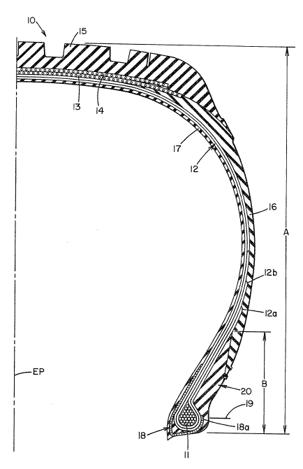
Referring now to Figs. 1 and 2 there is shown a
fragmentary cross-sectional view of a tire 10
~ according to the present invention and an enlarged
,'.','~3 fragmentary view of a bead portion and lower ~idewall
mounted upon a rim. A tire 10 according to the
,~,31~ present invention i9 similar to the prior art tire
~3 , which has already been described herein, the main
'difference9 being the elimination of the clamping
S member and the increase in the height of the turn-up
of the carcass ply(s).
A tire according to the present invention has a
;~ pair of axially space~ apart bead cores 11 which each
comprise a plurality of ~raps of a single metallic
filament. Each of the bead core~ has a radial
cross-sectional shape which is substantially
....
2 ~
- 6
i
pentagonal with the greatest axial width of the bead
core being located radially outwardly of the radially
innermost edge of the bead core. As used herein a
radial cross section" i9 a cross section taken in a
i~ 5 plane which contains the axis of rotation of a tire or
tire and rim assembly. As used herein, "substantially
~, pentagonal" is understood to mean a five sided cross
:l! section, even though some or all of the sides may be
curvilinear rather than rectilinear, as in a regular
l 10 pentagon. The radially outermost extent of the bead
`~ core being a vertex of two of the ~ides of the
: pentagon.
~ A carcass ply 12 and a toe guard 1~ are folded
-~ about each bead core 11 in the same manner as in prior
art tires. In the tires of the invention, however, it
`; has been found that a suitable locked in bead
arrangement, where no apex is used, can be achieved
without using a clamping member. The locking in of
the bead is achieved by the adhesion be~ween the high
turn-up and the main portion of the carcass ply, and
.!~ the restriction of the flange of rim 22 when the tire
~ is mounted on the rim and inflated. As can be seen in
- Figure 2 in particular, the entire bead constxuction
is below the top of the flange, and the pentagonal
shape of the bead complements the natural pressures
between the tire and the rim in holding the bead on
the rim when the tire is inflated. (Note that
pressure at ~he top of the bead, exerted by the
flange, would have a downward vector in the bead
'e, 30 core.) This is particularly true when tires employing
high inflation, e.g. 50 psi, use the bead construction
of the i~vention. Also, because the axially outer end
of the toe guard lB is clamped below the top of the
rim flange 22a, chances that the toe guard would
suffex a ply end separation are substantially reduced.
;3
:
- 7
.
'~! The high turn-up, and the consequent high area of
adhesive contact between the turn-up and the main
carcass ply, further stabilizes the bead.
The carcass ply 12 and toe guard 18 are encased
in suitable elastomeric compounds. I'he cable~ of the
carcass ply 12 are oriented .such that the tire
according to the invention i'3 what is commonly
referred to in the art as a :radial ply tire. It i9
~ believed to be an important feature of the invention
il 10 that the turnup portions of the carcass plies are
wholly disposed radially outwardly, and the axially
outer portion of each toe guard are disposed radially
inward of the specified outermost radius R of a rim 22
which is specified for use with the tire in the
YEAR BOO~ OF THE TIRE AND RIM ASSOCIATION, INC. for
the year in which the tire is manufactured, or in the
~ yearbook of The European Tyre & Rim Technical
;~ Organization for the year in which the tire is
,l manufactured. ~he Tire and Rim Association, Inc. is
head~uartered at 3200 West Market Street, Akron 44313,
U. S. A., and the "YEARBOOK" contains standards
appro~ed by the association for tire de~ignations,
dimensions, rim contours and dimensions, and other
data and notes necessary for tire/rim exchangeability.
The advantage of this particular arrangement of the
, bead core, carcass ply and toe guard i9 believed to be
desirable because of the good bead durability
, obtained, despite a reduction in the volume and weight
of the structure.
3, 30 A belt structure comprising a plurality of belt
plies 13, 14 is located radially outwardly of the
carcass ply ï2 ill a crown portion of the tire. An
elastomeric tread por~ion 15 is disposed radially
outwardly of the belt structure.
'~1 ` ;'`,`
2 ~ n ~ ,3
- 8
',`Z
, The metallic filament used in the bead cores of
the illustrated embodimen~ is 0.050 inch diameter high
.~a~ tensile steel wire coated with bronze to enhance its
~i bonding with rubber. Of course, depending upon the
tire size, other filament diameters could be used in
~Z practicing the invention.
Each of the bead cores 11 has a radial
i1 cross-sectional shape which is substantially
:! , pentagonal. For example, in a pick up truck tire of
'5 10 size LT 235/85R16, each of the bead cores may be
fabricated having eight radially superposed layers of
wraps of said single metallic filament. The number of
wraps in each layer, beginning with the radially
innermost layer being 4,5,6,5,4,3,2,1. For other
sizes of tires, different nu~bers of layers, and wraps
; in each layer may be used.
l The carcass ply and toe guard are encased in
-i suitable elastomeric compounds. It may be desirable
to interpose thin layer of a tough abrasion resistant
rubber, which does not extend radially outwardly
beyond the bead core, between the carcass ply and the
pentagonal bead core. This layer of a tough abrasion
; resistant rubber is intended to prevent chafing of the
cords of the carcass ply against any sharp edge of the
` 25 bead core. A tire according to the invention may have
j either a single carcass ply of ara~id cords, as
- illustrated in Fig. 3, or it may have a plurality of
carcass plies of polyester cords. Of course, the
combination of the number of carcass plies and cord
, 30 material is dependent upon the operating parameters
for a given tire. A tire according to the illustrated
embodiment has a toe guard CG~priSing 1260/3 Nylon 6,6
cords spaced at nineteen cords per inch and oriented
Z at 45 with respect to a plane which is parallel to
35 the equatorial plane EP of the tire. The equatorial
.>! - ~
'`'i
~ ~ 1 J~ 3
:
,i
. .
, plane is a plane midway between the tire sidewalls and
perpendicular to the axis of rotation of the tire.
The carcass ply turn up(s) is/are turned up
around pentagonal shaped bead bundle 11 and locked
against the main portion of the carcass ply 12 by the
sidewall 16. In the illustrated embodiment, two
carcass ply turn-ups with high ends (12a, 12b), are
i~l
¦ two and three inches, respectively, above mold ring
split location 19. It i9 believed that satisfactory
-~ 10 results will be obtained using carcass ply turn-ups of
about 1.5 to 3.5 inches above mold ring split location
,~ 13.
~, The mold split ring location is the point on the
tire where the bottom of the mold and the top of the
mold come together when the tire is placed in the
,~
~ mold. In the specific illustrated embodiment (see
:;. .
Figure 1), the axially outer end 18a of toe guard 18
about 0.2 inch above the mold split ring 19 (on a
16.32 inch diameter mold).
An axially outer elastomeric ~tiffening member 20
comprising an ela~tomeric compound having a Shore D
hardness of 30 or greater and a Young's Modulus of
3,400 pounds per square inch (p.s.i.) or greater is
' located axially outwardly of the carcass ply and
toe guard and extends from a radially inner end
located radially inwardly of the radially outermost
, extent of the bead core 11, to a radially outer end
*. ~ which is disposed radially outwardly of the flange of
rim 22. For example, in a tire of size LT 235/85R16,
having a maximum section height A of about 7.8 inches,
~F the axially outer stiffening member extends radially
outwardly a distance B of about 2.5 inches from tne
Sharp Diameter of the tire.
In an alternative embodiment, chafer 20 may
comprise coextruded compounds X and Y which have
,~
'I
::;
2 ~ ? 7 ~
1 o
,.
:~3,
different properties. The properties can be
engineered to provide extra stiffness to the inner
" portion Y of the chafer, to stiffen the lower sidewall
of the tire (to provide better handling). A less
5 stiff compound in the outer portion X of the chafer
`~ cushions the carcass ply and the turn-up from forces
~- encountered by the outside of the tire and minimizes
rim chafing.
It has been found that the present bead
'-, 10 construction i9 very stable and can demonstrate high
`~ stability usi.ng ply coat compounds and chafer
J~'- (stiffening) compounds having a broad range of
properties. Suitable properties for ply coat
compounds and stiffening piece compound fall in the
15 following ranges.
~i MODULUS ELONGATION SHORE 'D'
(MPa)
" 20 PLYCOAT 7.0-12.0 450~-750~
~ STIFFENING PIECE 9.0-15.0 120~-300% 30-45
i1
The axially outer stiffening member 20 aids in
moving stress concentrations away ~rom the ed~e of the
carcass ply 12, which is expected to aid in reducing
`~ failures due to separations of the tire components. A
'',3 ~` layer of ~idewall rubber 16 is disposed axially
`i~ outwardly of the carcass ply in the sidewall portion
of the tire in the usual manner.
Using the pre~ent construction, it has been found
tha~ the tire of the invention can be made without
using apexes, clamping members and chippers in the
bead area of the tire. This construc~ion is lighter
~i 35 in weight than prior art constructions, which provides
operating efficiencies. Production efficiencies are
also realized. It has been found that the
! 3
2~n~3
`.` - 11 -
, ~
', !
~? construction of the instant invention shows im-proved
bead durability.
The invention is further illustrated with
reference to the following example.
EXAMPLE
Tests were made comparing the durability of the
,~ bead construction of the preaent invention with the
bead construction of U.S. Patent 5,058,649 and with
conventional hexagonal shaped bead constructions. All
tires tested were size LT235/85R16 HT, and all were
made the same, except as delineated in the following
table. The "A" and "B" constructions were made
according to the '649 patent, and the "G" and "H"
, 15 constructions were made in accordance with the present
j invention. The control was a conventional tire with a
..;
~,' hexagonal bead.
Apex 1 comprises the rubber closest to the bead
and between the main portion of the carcass ply and
the turn-up, and apex 2 is the upper half of such
rubber when the apex i9 duplexed. ~pex 3 i9 rubber
~? outside the turn-up (i.e. on the rim side of the
:~.. ? tire), and apex 4 is rubber between the main portion
.~ of the carcass ply and the inner liner.
,~
,.j
i i
~1
,~
:`
~; ~
2 ~
,` - 12
~'"
. .~
` BEAD II~PROVEMENT LT2 3 5 / 8 5 Rl 6 HT
; .j~ LOCKED TIE - IN
,;,'~ _ _ . . . .
5 Construotion A B a H H ¦ A
.';~ ¦ CONTROL
_ ___ _ _ _==
-.~, PLY FABRIC S.M.S.l~f. H.M. H.M. H.M. S.M.
:! COMPD Z 2 3 4 4 3
.` GAUae .052 056 059 .062 059 059
~, BBAD PEINTPENT P'eNTPeNT PE!NT ileX
auM PLIPPER NONP Y8S Y~S I`iONe NON~ NONE!
_ . .
APEX I COMPD YES YES NONP NON~ NONB YPS
.. __ _ .. _
;~ APeX 3 COMPD NONE NONe NONE NONE NONE Y~S
::' _ _ .___
APeX 4 COMPD YES YES NON~ NONe NONP NoNe
"i` I _ _ ,__ ...
.~. BBAD OllT (rni) 4,883 2,336 6,063 8,632 5,768 5,138
I .7 ~25 7,200 6,475 6'407 6,619 6,037
FAT CAP
~ INDE.Y ~ .865 ~ .480 I .98 2.04 I ,94
-:~ ¦ 90% LIMIT+/. 240 +/- 1006 +1- 1187 +/- 1062 +/- 376
ATE (rni)
:~ rt froDt 45 C00 SF 30 000 SF
~3 2 0 lt 8ront 45 000 SF 30 000 SF
n roar 45,000 SP 30,000 P
,X It rcar 45,000 SP 30,000 P
= . _.~ . . __ - - --. . ,, _
l SF = Stop/Finish F = Failed
The ply fabric in each tire tested comprised
1300d/3 cables (3900 denier total) polyester at 27
epi. S.M. refers to standard modulus, and H.M. refers
to high modulus cables. (The high modulus cables are
the same a~ standard modulus cables except that the
H.M. cables were heated and stretched.)
The ply coat compounds used in each construction
had the following properties.
:1,
i
~1,
!~; 2 :~ ~ ~ 3 ~ ~
~ - 13 -
,~
; Modulus i2 Tensile ~3Elongation~ ~80
(MPa) (MPa)
, 1. 13 16 350
~ 2. 9 21 580
`` 5 3. 7 21 600
-;J 4. 9 ~5 420
:
The Fat Cap index is a step load test where r at
~ one end of the scale, the load is increased 7% every
;~ 10 100 miles, and at the other end of the scale, the load
'', i9 increased 7~ every 800 miles. The load at failure
for each test of each tire construction is plotted,
and the slope of the line i9 the index. In this test,
higher numbers indicate better results.
The Bead-Out test is a severe condition test
where the tire is inflated to 80% of its rated
;! inflation, and a load comprising 200% of the rated
~:~ load for test inflation is applied~ The results of
i~;
~ the test are defined by the number of miles a tire
runs under the defined conditions. The results
demon~trate more repeatable results for the G and H
constructions as compared to the A and B constructions
and the control, and an improvement in durability of
the G and H constructions over the control.
The ATE test (actual vehicle testing at 110%
load) shows improved results for the one H
~` construction tested.
~-~ While certain representative embodiments and
details have been shown for the purpose of
illustrating the invention, it will be apparent to
those skilled in the art that various changes and
modificatiolls may be made therein without deviating
from the spirit or scope of the invention.
:
!